Page is loading ...

Installation Manual
DCT2500
Digital Consumer
Terminal
POWER
CURSOR SELECT
MENU
INFO
GUIDE
CHANNEL
MESSAGES REMOTE
ON

Graphical symbols and supplement warning marking locations on the bottom of the appliance.
This symbol indicates that dangerous voltage levels are present within the equipment. These voltages are not insulated
and may be of sufficient strength to cause serious bodily injury when touched. The symbol may also appear on
schematics.
This symbol calls attention to a critical procedure, or means refer to the instruction manual for opening or service
information. Only qualified service personnel are to install or service the equipment. The symbol may also appear in text
and on schematics.
WARNING:
TO PREVENT FIRE OR SHOCK HAZARD, DO NOT EXPOSE THIS APPLIANCE TO RAIN OR MOISTURE.
CAUTION:
TO PREVENT ELECTRICAL SHOCK, DO NOT USE THIS PLUG WITH AN EXTENSION CORD, RECEPTACLE, OR OTHER OUTLET
UNLESS THE BLADES CAN BE FULLY INSERTED TO PREVENT BLADE EXPOSURE.
FCC Compliance: Federal Communications Commission Radio and Television Interface Statement for a Class ‘B’ Device
This equipment has been tested and found to comply with the limits for a Class B digital device, pursuant to part 15 of the FCC Rules. These
limits are designed to provide reasonable protection against harmful interference in the residential installation. This equipment generates, uses
and can radiate radio frequency energy and, if not installed and used in accordance with the instructions, may cause harmful interference to radio
communications. However, there is no guarantee that interference will not occur in a particular installation.
If the equipment does cause harmful interference to radio or television reception, which can be determined by turning the equipment off and on,
the user is encouraged to try to correct the interference by one of the following measures:
Increase the separation between the equipment and the affected receiver
Connect the equipment on a circuit different from the one the receiver is on
Ensure that the cover plate for the security card is secured and tight
Changes or modification not expressly approved by the party responsible for compliance could void the user’s authority to operate the equipment.
Declaration of Conformity: According to 47 CFR, Parts 2 and 15 for Class B Personal Computers and Peripherals; and/or CPU Boards and
Power Supplies used with Class B Personal Computers, Motorola, Inc., 6450 Sequence Drive, San Diego, CA 92121, 1-800-225-9446, declares
under sole responsibility that the product identifies with 47 CFR Part 2 and 15 of the FCC Rules as a Class B digital device. Each product
marketed is identical to the representative unit tested and founded to be compliant with the standards. Records maintained continue to reflect the
equipment being produced can be expected to be within the variation accepted, due to quantity production and testing on a statistical basis as
required by 47 CFR 2.909. Operation is subject to the following condition: This device must accept any interference received, including
interference that may cause undesired operation. The above named party is responsible for ensuring that the equipment complies with the
standards of 47 CFR, Paragraphs 15.107 to 15.109
FCC Part 68 Statement:
This equipment complies with part 68 of the FCC rules. On the rear panel of this equipment is a label that contains, among
other information, the FCC registration number and ringer equivalence number (REN) for the equipment. If requested, this information must be provided to
the telephone company.
The REN is used to determine the quantity of devices that may be connected to the telephone line. Excessive RENs on the telephone line may result in the
devices not ringing in response to an incoming call. In most, but not all areas, the sum of the RENs should not exceed five (5.0). To be certain of the number
of devices that may be connected to the line, as determined by the total RENs, contact the telephone company to determine the maximum REN for the
calling area.
This equipment uses the following USOC jack: RJC. An FCC-compliant telephone cord and modular plug is provided with this equipment. This equipment is
designed to be connected to the telephone network or premises wiring using a compatible modular jack that is Part 68 compliant. This equipment cannot be
used on telephone company-provided coin services. Connection to Party Line Service is subject to state tariffs.
If this equipment causes harm to the telephone network, the telephone company will notify you in advance that the temporary discontinuance of services
may be required. If advance notice isn’t practical, the telephone company will notify the customer as soon as possible. Also, you will be advised of your right
to file a compliant with the FCC if you believe it is necessary.
The telephone company may make changes in its facilities, equipment, operations, or procedures that could affect the operation of the equipment. If this
happens, the telephone company will provide advance notice in order to maintain uninterrupted service.

If the trouble is causing harm to the telephone system, the telephone company may request that you remove the equipment from the network until the
problem is resolved.
It is recommended that the customer install an AC surge arrestor in the AC outlet to which this device is connected. This is to avoid damaging the
equipment by local lightning strikes and other electrical surges.
Canadian Compliance: This Class B digital apparatus meets all requirements of the Canadian Interference-Causing Equipment Regulations.
Cet appareil numérique de la classe B respects toutes les exigences du Règlement sur le matériel brouilleur du Canada.
Industry Canada CS-03 Statement:
The Industry Canada label identifies certified equipment. This certification means that the equipment meets certain
telecommunications network protective, operational and safety requirements as prescribed in the appropriate Terminal Equipment Technical Requirements
document(s). The department does not guarantee that the equipment will operate to the user’s satisfaction.
Before installing this equipment, users should ensure that it is permissible to be connected to the facilities of the local telecommunications company. The
equipment must also be installed using an acceptable method of connection. The customer should be aware that compliance with the above conditions
might not prevent degradation of service in some situations. Repairs to certified equipment should be coordinated by a representative designated by the
supplier. Repairs or alterations made by the user to this equipment, or equipment malfunctions may give the telecommunication company cause to request
the user to disconnect the equipment.
Users should ensure for their own protection that the electrical ground connections of the power utility, telephone lines and internal metallic water pipe
system, if present, are connected together. This precaution may be particularly important in rural areas. Users should not attempt to make such connections
themselves, but should contact the appropriate electric inspection authority, or electrician, as appropriate.
The Ringer Equivalence Number (REN) of this device is 0.4. The Ringer Equivalence Number (REN) assigned to each terminal device provides an
indication of the maximum number of terminals allowed to be connected to a telephone interface. The termination on an interface may consist of any
combination of devices subject only to the requirement that the sum of the Ringer Equivalence Numbers of all devices does not exceed 5. The telephone
connection arrangement is a CA11A.
Repairs: If repair is necessary, call the Motorola Repair Facility at 1-800-227-0450 for a Return for Service Authorization (RSA) number before
sending the unit. The RSA number must be prominently displayed on all equipment cartons. Pack the unit securely; enclose a note describing the
exact problem, and a copy of the invoice that verifies the warranty status. Ship the unit PRE-PAID to the following address:
Motorola, Inc.
Attn: RSA #___________
c/o Rudolph Miles and Sons
2500 Courage Boulevard
Brownsville, TX 78521
NOTE TO CATV SYSTEM INSTALLER: This reminder is provided to call CATV system installer’s attention to Article 820-40 of the NEC that
provides guidelines for proper grounding and, in particular, specifies that the cable ground shall be connected to the grounding system of the
building, as close as possible to the point of cable entry as practical.
Copyright © 2003 by Motorola, Inc.
All rights reserved. No part of this publication may be reproduced in any form or by any means or used to make any derivative work (such as
translation, transformation or adaptation) without written permission from Motorola, Inc.
Motorola reserves the right to revise this publication and to make changes in content from time to time without obligation on the part of Motorola to
provide notification of such revision or change. Motorola provides this guide without warranty of any kind, either implied or expressed, including,
but not limited to, the implied warranties of merchantability and fitness for a particular purpose. Motorola may make improvements or changes in
the product(s) described in this manual at any time.
MOTOROLA and the Stylized M Logo are registered in the US Patent & Trademark Office. STARVUE and STARFONE are registered trademarks
of Motorola, Inc. Manufactured under license from Dolby Laboratories. "Dolby" and the double-D symbol are registered trademarks of Dolby
Laboratories. All other product or service names are the property of their respective owners.

DCT2500 Installation Manual
Contents
Section 1
Introduction
Features, Options, and Interfaces ..........................................................................................................................................1-1
Using This Manual.................................................................................................................................................................. 1-2
Related Documentation .......................................................................................................................................................... 1-2
Document Conventions..........................................................................................................................................................1-3
If You Need Help.....................................................................................................................................................................1-3
Calling for Repairs.................................................................................................................................................................. 1-3
Section 2
Overview
Front Panel .............................................................................................................................................................................2-1
Rear Panel............................................................................................................................................................................... 2-2
Options ................................................................................................................................................................................... 2-4
Audio Output Modes...............................................................................................................................................................2-5
Section 3
Installation
Before You Begin....................................................................................................................................................................3-1
Installing the DCT2500............................................................................................................................................................3-1
Standard Cabling Diagram .....................................................................................................................................................3-2
Standard VCR Cabling Diagram.............................................................................................................................................3-3
VCR Cabling With RF Bypass Switch Diagram......................................................................................................................3-4
A/B In Module Cabling Diagrams ...........................................................................................................................................3-5
Composite Baseband and S-Video Cabling Diagrams........................................................................................................... 3-7
Stereo Cabling Diagram (Baseband)......................................................................................................................................3-9
Home Theater Receiver Cabling Diagram ............................................................................................................................ 3-11
Operational Check................................................................................................................................................................ 3-13
Section 4
Adding the IR Blaster Option
Locating the IR Receiver on the VCR..................................................................................................................................... 4-1
Installing the IR Blaster ..........................................................................................................................................................4-2
Checking the Installation........................................................................................................................................................4-2

ii Contents
DCT2500 Installation Manual
Section 5
Troubleshooting
Appendix A
Diagnostics
Using Diagnostics.................................................................................................................................................................. A-2
d 01: General Status............................................................................................................................................................... A-3
Error Codes ................................................................................................................................................................... A-5
V860DLd 02: Out-of-Band (OOB) Diagnostic......................................................................................................................... A-6
Selecting the OOB Frequency....................................................................................................................................... A-7
d 03: In-band Status............................................................................................................................................................... A-8
d 04: Audio/Video Status ....................................................................................................................................................... A-9
d 05: Unit Address ............................................................................................................................................................... A-10
d 06: Firmware Version........................................................................................................................................................ A-11
d 07: Current Channel Status .............................................................................................................................................. A-11
d 08: Renewable Security .................................................................................................................................................... A-13
d 09: Upstream Diagnostics................................................................................................................................................. A-14
RF Return (STARVUE II) Diagnostics.......................................................................................................................... A-14
Telephone Modem (STARFONE) Diagnostics............................................................................................................. A-15
d 10: Application (APP) Code Modules ............................................................................................................................... A-17
d 11: Memory Status............................................................................................................................................................ A-18
d 12: Interactive Info ............................................................................................................................................................ A-18
d 13: MAC Frequency Table................................................................................................................................................. A-19
d 14: Control Channels........................................................................................................................................................ A-20
d 15: Message Types ........................................................................................................................................................... A-20
d 16: In-band Program Association Table (PAT)................................................................................................................. A-20
d 17: In-band Program Map Table (PMT)............................................................................................................................. A-20
d 18: Task Status ................................................................................................................................................................. A-21
d 19: USB Diagnostics ......................................................................................................................................................... A-21
d 20: In-band Multicast Address Filter................................................................................................................................. A-22
d 21: Keyboard / LED Diagnostics....................................................................................................................................... A-22
Abbreviations and Acronyms

Contents iii
DCT2500 Installation Manual
Figures
Figure 1-1 Front and rear views.............................................................................................................................................1-2
Figure 2-1 Front panel ............................................................................................................................................................2-1
Figure 2-2 Rear panel.............................................................................................................................................................2-2
Figure 2-3 Options available for the DCT2500.......................................................................................................................2-4
Figure 3-1 Standard cabling to a TV using RF connectors................................................................................................... 3-2
Figure 3-2 Standard VCR cabling.......................................................................................................................................... 3-3
Figure 3-3 Cabling with the RF Bypass module (using RF return) .......................................................................................3-4
Figure 3-4 A/B In module on a DCT2500 using optional telco return ...................................................................................3-5
Figure 3-5 A/B In module on a DCT2500 with the return on Cable A.................................................................................... 3-5
Figure 3-6 A/B In module on a DCT2500 with return on Cable B.......................................................................................... 3-6
Figure 3-7 Standard baseband audio and video outputs...................................................................................................... 3-7
Figure 3-8 Composite VCR cabling ....................................................................................................................................... 3-8
Figure 3-9 Connecting the DCT2500 to a stereo using the audio connectors on the VCR ..................................................3-9
Figure 3-10 Audio on VCR/audio output on TV................................................................................................................... 3-10
Figure 3-11 Connections to a home theater receiver using DIGITAL AUDIO COAX................................................................... 3-11
Figure 3-12 Connections to a home theater receiver using DIGITAL AUDIO OPTICAL............................................................... 3-12
Figure 4-1 IR transmitter installed in mounting bracket ....................................................................................................... 4-1
Figure 4-2 IR Blaster installed ............................................................................................................................................... 4-2
Tables
Table 2-1 Front panel controls and LEDs..............................................................................................................................2-1
Table 2-2 Rear panel features................................................................................................................................................2-2
Table 2-3 Options....................................................................................................................................................................2-4
Table 3-1 Operational check procedures ............................................................................................................................ 3-13
Table 5-1 Troubleshooting guidelines................................................................................................................................... 5-1

DCT2500 Installation Manual
Section 1
Introduction
This manual provides instructions to install the Motorola DCT2500 analog/digital set-top
terminal. The DCT2500:
! Supports 64 and 256 QAM digital signal formats
! Is compatible with existing Motorola analog and digital set-tops, which are not affected by
the new data the addressable controller sends to the DCT2500s
! Uses digital compression technology to provide new revenue generating services
! Can be configured to support real time reverse path communications, enabling interactive
services such as Video on Demand (VOD), Internet access, e-mail, and home shopping
Features, Options, and Interfaces
The Motorola DCT2500 offers the following standard features:
! 54 to 860 MHz integrated tuner
! Integrated RF return (using built-in STARVUE II module)
! RF and baseband audio/ video ports
! IR Blaster port
! Switched accessory outlet
! RS 232 serial data port (provides a high speed serial data interface)
! Coaxial digital audio output
Optional features include:
! Expanded memory
! STARFONE
II (14.4 kbps) Telco return
! A/B In switch
! RF Bypass switch
! IR Blaster cable
! S-Video output
! TOSlink optical digital audio output
! USB port
! Analog descrambling

1-2 Introduction
DCT2500 Installation Manual
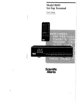
Figure 1-1 illustrates front and rear views of the DCT2500:
Figure 1-1
Front and rear views
POWER
CURSOR SELECT
MENU INFO
GUIDE
CHAN NEL
MESSAGES REMOTE
ON
AUDIO
OUT
TO
RF IN
TO
TV/VCR
RF IN
CABLE
IN
DIGITAL
AUDIO
OPTICAL
DIGITAL
AUDIO
COAX
VIDEO
DATA
USB
IR
PHONE
TV PASS CARD
SWITCHED
105-125V
60Hz
4A MAX
500W MAX
S-VIDEO
R
TO TV
TO VCR
L
Using This Manual
This manual provides instructions to install and configure a DCT2500:
Section 1 Introduction provides a product description, a list of related documentation, the technical
helpline telephone number, and the repair/return procedure.
Section 2 Overview describes the DCT2500 and provides an overview of its use. This section also
identifies the front-panel displays and switches and describes the rear-panel features.
Section 3 Installation provides instructions on how to install the DCT2500 in a subscriber location
and perform operational tests.
Section 4 Adding the IR Blaster Option provides instructions on how to install the IR Blaster option
for controlling VCR recording through the DCT2500.
Section 5 Troubleshooting provides guidelines for troubleshooting the equipment.
Appendix A Specifications provide the technical specifications for the DCT2500.
Appendix B Diagnostics provide instructions on accessing and interpreting the built-in diagnostics.
Abbreviations
and
Acronyms
The Abbreviations and Acronyms list contains the full spelling of the short forms used in
this manual.
Related Documentation
Separate instruction manuals are available for associated components. Although the DCT2500
User Guide may be useful, it is not necessary to install or operate the basic DCT2500 if you
have this manual.

Introduction 1-3
DCT2500 Installation Manual
Document Conventions
Before you begin working with this manual and using the DCT2500, familiarize yourself with
the stylistic conventions used in this manual:
SMALL CAPS
Denotes silk screening on the equipment, typically representing front- and rear-panel
controls, input/output (I/O) connections, and LEDs
* (asterisk)
Indicates that several versions of the same model number exist and the information
applies to all models; when the information applies to a specific model, the complete
model number is given
Italic type Used for emphasis
Courier font
Displayed text
If You Need Help
If you need assistance while working with the DCT2500, contact the Motorola Technical
Response Center (TRC):
! Inside the U.S.: 1-888-944-HELP (1-888-944-4357)
! Outside the U.S.: 215-323-0044
! Online: http://broadband.motorola.com/noflash/websupport.html
.
The TRC is open from 8:00 AM to 2:00 AM Eastern Time, Monday through Friday and
10:00 AM to 5:00 PM Eastern Time, Saturday. When the TRC is closed, emergency service only
is available on a call-back basis. Web Support offers a searchable solutions database, technical
documentation, and low priority issue creation/tracking 24 hours per day, 7 days per week.
Calling for Repairs
If repair is necessary, call the Motorola Repair Facility at 1-800-227-0450 for a Return for
Service Authorization (RSA) number before sending the unit. The RSA number must be
prominently displayed on all equipment cartons. The Repair Facility is open from 8:00 AM to
5:00 PM Central Time, Monday through Friday.
When calling from outside the United States, use the appropriate international access code and
then dial 956-541-0600 to contact the Repair Facility.
When shipping equipment for repair, follow these steps:
1 Pack the unit securely.
2 Enclose a note describing the exact problem. Complete and enclose the checklist provided
with the unit.
3 Enclose a copy of the invoice that verifies the warranty status.
4 Ship the unit PREPAID to the following address:
Motorola, Inc.
c/o Rudolph Miles & Son, Inc.
Attn: RSA # ___________
5964 E. 14
th
Street
Brownsville, TX 78521

DCT2500 Installation Manual
Section 2
Overview
This section provides illustrations and tables showing the controls, displays and connectors.
Before you begin to install the DCT2500, familiarize yourself with its controls and displays.
Front Panel
The front panel contains selection keys, tuning keys, various displays, and the power switch.
These controls provide minimum yet functional capability if the remote control is lost or
temporarily out of service. Functions requiring a numeric entry are not available without a
remote control.
Figure 2-1
Front panel
POWER
CURSOR SELEC T
MENU INFO
GUI DE
CHANNEL
ME SS AG ES REM OT E
ON
12
891011
4
5
6
3
7
Table 2-1
Front panel controls and LEDs
Key Feature Function
1
CURSOR SELEC T
Moves the cursor in menus and electronic program guide (EPG) screens
2
MESSAGES
Lights to indicate that a message is present
3
ON
Lights when the unit is turned on
4
Displays current channel number or time of day
5
REMO TE
Flashes when a signal is received from the remote control
6
CHA NNEL
Changes the channel up and down

2-2 Overview
DCT2500 Installation Manual
Key Feature Function
7
CURSOR SELEC T
Selects menu options, Pay-Per-View (PPV) events, and tunes channels
from the EPG
8
POWER
Turns the DCT2500 on and off
9
MENU
Displays the main menu
10
INFO
Displays current channel and program information
11
GU IDE
Displays the EPG
Rear Panel
The rear panel contains a switched power outlet and connectors for video, audio, RF cabling,
data output, and the IR Blaster:
Figure 2-2
Rear panel
AUDIO
OUT
TO
RF IN
TO
TV/VCR
RF IN
CABLE
IN
DIGITAL
AUDIO
OPTICAL
DIGITAL
AUDIO
COAX
VIDEO
DATA
USB
IR
PHONE
TV PA SS CARD
SWITCHED
105-125V
60Hz
4A MAX
500W MAX
S-VIDEO
R
TO TV
TO VCR
L
1
78910111213141516
25 634
Table 2-2
Rear panel features
Key Item Function
1
RF IN
A coaxial input that is connected to the TO RF IN.
2
TO
RF I N
A coaxial input that directs the cable signal to other connections on the
DCT2500.

Overview 2-3
DCT2500 Installation Manual
Key Item Function
3
AUDI O
OUT
R
TO TV
TO VCR
L
Right/left RCA stereo outputs connect the DCT2500 to the TV. The
audio output to the TV is volume controlled.
4
AUDI O
OUT
R
TO TV
TO VCR
L
Right/left RCA stereo outputs connect the DCT2500 to the VCR. The
audio output to the VCR is line level.
5
DATA
A high-speed serial interface for connecting an optional external high
definition TV decoder (do not connect the PC to this interface)
6
SWITCHED
105-125V
60Hz
4A MAX
500W MAX
This is a two-plug AC power connector:
! The bottom plug is an input for the AC power cord
! The top plug is a switched power outlet for another device such as
a TV or VCR into
7
TO
TV/VCR
A coaxial output to connect the DCT2500 to the TV or VCR.
8
CABL E
IN
A coaxial input for the incoming signal from the wall outlet.
9
S-VIDEO
An S-Video connector for sending high quality video to external
devices (high-end VCR or TV) that accept S-Video. (Optional)
10
VIDEO
This RCA video output connects the DCT2500 to an input on a TV,
VCR, or other device.
11
DI GITA L
AUDIO
COAX
A coaxial audio output to connect the DCT2500 to a digital home
theater receiver or A/V receiver.
12
DI GITAL
AUDIO
OPTICAL
A Toslink connector to connect the DCT2500 to a digital home theater
receiver. (Optional)
13
TV PASS C
A
Reserved for future use
14
USB
The Universal Serial Bus (USB) is used to connect to devices such as
keyboards, joysticks, scanners, disk storage, PCs, printers, and digital
cameras, if supported. (Optional)
15
IR
A stereo mini-phone connector connecting the optional Infrared (IR)
Blaster attachment for the DCT2500.
16
PHON E
RJ-11 telephone modem output to connect to the telephone line for
systems using telco-return. (Optional)

2-4 Overview
DCT2500 Installation Manual
Options
The following options enable you to meet individual subscriber needs:
Figure 2-3
Options available for the DCT2500
AUDIO
TO
RF IN
TO
TV/VCR
RF IN
CABLE
IN
DIGITAL
AUDIO
OPTICAL
DIGITAL
AUDIO
COAX
VIDEO
DATA
USB
IR
PHONE
TV PASS CARD
SWITCHED
105-125V
60Hz
4A MAX
500W MAX
S-VIDEO
R
TO TV
TO VCR
L
CABLE IN
A
B
RF
OUT
RF
IN
CONV
IN
1
23
4
65
DCT2500
Table 2-3
Options
Key Option Name Function
1
S-V I DEO
S-VIDEO
An S-Video connector for sending high quality video to
external devices (high-end VCR or TV) that accept
S-Video.
2
CABLE IN
A
B
A/B In
Used in a dual cable system to receive both cables;
verify the location of the A and B connectors on the
A/B In module
3
RF
OUT
RF
IN
CONV
IN
RF Bypass
Enables the cable signal to bypass the DCT2500 and
go directly to a TV or VCR
4
DI GITAL
AUDIO
OPTICAL
Optical
A Toslink connector to connect the DCT2500 to a
digital home theater receiver.
5
USB
USB
USB is used to connect to devices such as keyboards,
joysticks, scanners, disk storage, PCs, printers, and
digital cameras, if supported.

Overview 2-5
DCT2500 Installation Manual
Key Option Name Function
6
PHON E
PHONE
RJ-11 telephone modem output to connect to the
telephone line for systems using telco return
Audio Output Modes
The DCT2500 includes utilities that enable you to select and adjust its DIGITAL AUDIO (coaxial
or optical) or
AUDIO OUT (RCA style) outputs. If the EPG takes advantage of these utilities, it
provides menu choices to select and optimize the audio output and compression modes. For
more information about audio output mode configuration, refer to the EPG user manual.

DCT2500 Installation Manual
Section 3
Installation
This section provides installation and cabling instructions. To complete the installation, you
must:
! Connect the cables
! Supply power to equipment
! Download configuration information and software
! Run operational check and diagnostics
Before You Begin
Before you begin, review the installation instructions, gather the required items, and complete
the following tasks:
! Determine if the subscriber requirements include an A/B In, or RF Bypass module. You can
install these options before leaving the office following the instructions provided with each
module.
! Verify that you have 75-ohm coaxial cables with F-type connectors and RCA baseband
phono-type cables.
! Determine if you are connecting the DCT2500 to a standard TV or a composite (baseband)
monitor.
! Place the DCT2500 on a smooth, flat surface and remove any obstructions that could
interfere with the free flow of air over, under, or around it. Advise the subscriber not to
place anything on top of the unit.
Installing the DCT2500
To install the DCT2500:
1 Determine if you are connecting the DCT2500 to a conventional TV or to a monitor. To
install the video connection:
! For a conventional TV, use a 75-ohm coaxial cable with F-type connectors.
! For a monitor, use an RCA phono cable to connect the
VIDEO connector to the monitor.
2 Locate the cabling diagram that most closely matches the subscriber’s configuration
requirement.
3 Connect the cables as illustrated in the diagram.
4 Perform the basic operational check in this section after the DCT2500 is installed.
5 If you are using the Telco return option, connect the DCT2500 to the subscriber’s phone
line.

3-2 Installation
DCT2500 Installation Manual
Standard Cabling Diagram
The DCT2500 outputs on channel 3 or 4, depending on the configuration from the addressable
controller:
Figure 3-1
Standard cabling to a TV using RF connectors
AUDIO
OUT
TO
RF IN
TO
TV/VCR
RF IN
CABLE
IN
DIGITAL
AUDIO
OPTICAL
DIGITAL
AUDIO
COAX
VIDEO
DATA
USB
IR
PHONE
TV PASS CARD
SWITCHED
105-125V
60Hz
4A MAX
500W MAX
S-VIDEO
R
TO TV
TO VCR
L
DCT2500
CABLE IN VIDEO
IN
S-VIDEO
IN
AUDIO
IN
LR
AUDIO
OUT
LR
TV
From cable outlet

Installation 3-3
DCT2500 Installation Manual
Standard VCR Cabling Diagram
Figure 3-2 illustrates the basic cabling required to record the channel being viewed:
Figure 3-2
Standard VCR cabling
AUDIO
OUT
TO
RF IN
TO
TV/VCR
RF IN
CABLE
IN
DIGITAL
AUDIO
OPTICAL
DIGITAL
AUDIO
COAX
VIDEO
DATA
USB
IR
PHONE
TV PASS CARD
SWITCHED
105-125V
60Hz
4A MAX
500W MAX
S-VIDEO
R
TO TV
TO VCR
L
DCT2500
CABLE IN VIDEO IN
AUDIO
IN LR
CABLE OUT VIDEO OUT
AUDIO
OUT LR
S-VIDEO IN
S-VIDEO OUT
VCR
CABLE IN VIDEO
IN
S-VIDEO
IN
A
UDIO
IN
LR
A
UDIO
OUT
LR
TV
From cable outlet

3-4 Installation
DCT2500 Installation Manual
VCR Cabling With RF Bypass Switch Diagram
The RF Bypass module enables viewing of an unscrambled analog channel on TV while
recording another channel through the DCT2500. Proper RF Bypass operation requires special
configuration on the addressable controller and the EPG.
Figure 3-3
Cabling with the RF Bypass module (using RF return)
AUDIO
TO
RF IN
TO
TV/VCR
RF IN
CABLE
IN
DIGITAL
AUDIO
OPTICAL
DIGITAL
AUDIO
COAX
VIDEO
DATA
USB
IR
PHONE
TV PASS CARD
SWITCHED
105-125 V
60Hz
4A MAX
500W MAX
S-VIDEO
R
TO T V
TO VCR
L
DCT2500
TV
CABLE IN
VIDEO
IN
SVIDEO
IN
A
UDIO
IN
LR
A
UDIO
OUT
LR
VCR
CABLE IN VIDEO IN
AUDIO
IN LR
CABLE OUT VIDEO OUT
AUDIO
OUT
LR
SVID EO IN
SVIDEO OUT
From cable source
RF
OUT
RF
IN
CONV
IN

Installation 3-5
DCT2500 Installation Manual
A/B In Module Cabling Diagrams
The A/B In module is commonly used in dual-cable systems.
Figure 3-4
A/B In module on a DCT2500 using optional telco return
AUDIO
TO
RF IN
RF IN
CABLE
IN
DIGITAL
AUDIO
OPTICAL
DIGITAL
AUDIO
COAX
VIDEO
DATA
USB
IR
PHONE
TV PASS CARD
SWITCHED
105-125V
60Hz
4A MAX
500W MAX
S-VIDEO
R
TO T V
TO VCR
L
DCT2500
TV
CABLE IN
VIDEO
IN
SVIDEO
IN
AUDIO
IN
LR
AUDIO
OUT
LR
CABLE IN
A
B
Cable A
Cable B
Subscriber
telephone
hookup
TO
TV/VCR
Figure 3-5
A/B In module on a DCT2500 with the return on Cable A
AUDIO
TO
RF IN
TO
TV/VCR
RF IN
CABLE
IN
DIGITAL
AUDIO
OPTICAL
DIGITAL
AUDIO
COAX
VIDEO
DATA
USB
IR
PHONE
TV PASS CARD
SWITCHED
105-125V
60Hz
4A MAX
500W MAX
S-VIDEO
R
TO TV
TO VCR
L
TV
DCT2500
CABLE IN
VIDEO
IN
SVIDEO
IN
AUDIO
IN
LR
AUDIO
OUT
LR
Cable B
Cable A (Return)
RF OUT
A
B

3-6 Installation
DCT2500 Installation Manual
Figure 3-6
A/B In module on a DCT2500 with return on Cable B
AUDIO
TO
RF IN
TO
TV/VCR
RF IN
CABLE
IN
DIGITAL
AUDIO
OPTICAL
DIGITAL
AUDIO
COAX
VIDEO
DATA
USB
IR
PHONE
TV PASS CARD
SWITCHED
105-125V
60Hz
4A MAX
500W MAX
S-VIDEO
R
TO T V
TO VCR
L
DCT2500
TV
CABLE IN
VIDEO
IN
SVIDEO
IN
AUDIO
IN
LR
AUDIO
OUT
LR
Cable A
Cable B (Return)
CABLE IN
A
B
/