Page is loading ...

PR20—1
220 MHz
LOW NOISE
PREAMP
KIT
• 16 db Gain, 1 db Noise Figure
• Runs on 9 to 15 VDC
• Hi-Q tuned input to reduce
overload
• Small size to fit in any rig
• The most popular preamp kit in
the USA!
• Easy 15 minute assembly
Perk up your reception on 220 MHz with this easy-to-build and install kit.
Works well with any radio - especially effective in repeaters. Rugged design
using a microwave transistor outperforms units costing triple the price!
Kit No. PR20

PR20—2
INTRODUCTION TO THE PR20 LOW NOISE PREAMPLIFIER
A “preamplifier” gives an initial boost, measured in decibels, to the level of a signal before it
is further processed by tuned circuits, filters, amplifiers, mixers, detectors, or other circuit
stages. Preamps may be designed for either RF or audio use and may be either tuned or
broadbanded.
The Ramsey Low Noise PR10, 20, and 40 Preamplifiers for 144, 220, and 440 MHz,
respectively, differ from our popular SA7 and PR2 broadband preamplifiers in that these
models include high-Q tuned input circuits to pre-select the desired frequency range,
restricting the strength of other out-of-band signals. Also, the microwave transistor is biased
for best low noise performance.

PR20—3
CIRCUIT DESCRIPTION
L1 and C2 form a tuned input filter for the preamp to reject out-of-band signals. The 3 db
bandwidth of this filter is 6MHz. L1 is adjustable for peak performance. The 2SC2498
transistor is a bipolar silicon NPN low noise UHF/VHF amplifier in a TO-92 case suitable for
service up to 5 GHz, with maximum device dissipation of 600 milliwatts. Q1 has a very low
noise figure, determined by the bias established by R1 and R2. The actual circuit is about
as simple as they come. Maximum gain and freedom from oscillation are accomplished by
the quality of workmanship in parts installation and I/O connector wiring

PR20—4
PARTS SUPPLIED WITH PR20 KIT
CAPACITORS
2 2 or 2.2pF disc capacitor (C1,2)
1 10pF disc capacitor (C3)
1 100pF disc capacitor [marked 100 or 101] (C4)
1 .01uF disc capacitor [may be marked .01, 103, or 10nF] (C5)
RESISTORS
1 470 ohm [yellow-violet-brown] (R1)
1 100K ohm [brown-black-yellow] (R2)
OTHER COMPONENTS
1 PRX printed circuit board
1 shielded adjustable coil (L1) [marked 359-7787]
1 2SC2498 or 2570 microwave bipolar transistor (Q1)
REQUIRED, NOT SUPPLIED
9 - 15 VDC power source
RF input and output connectors (your choice of type)

PR20—5
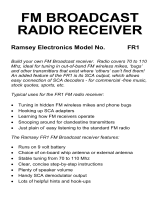
RAMSEY PR20 PRE-AMP PARTS LAYOUT
NOTE FOR PR-20:
Disregard C6
*

PR20—6
PR20 PRE-AMP ASSEMBLY PROCEDURE
Soldering nine parts to a PC board is not a big job, but good performance of the PR20
requires attention to keeping all leads as short and neat as possible. The order of parts
installation is not critical for this and other small kits, so the purpose of the following
suggested order of assembly is just to make it as easy as possible for you to get the parts
placed correctly on the first try. For your convenience, the PC board is considerably
enlarged. While working with a small PC board such as the PR20, a miniature vise plus a
magnifier may prove very helpful.
In all steps below, the word install means to insert the component (oriented correctly) into
the right holes, solder all wires, and cut or nip away excess wire flush with the solder
connection. IMPORTANT: Keep ALL component leads as short as possible!
1. Install R1, 470 ohm (yellow-violet-brown). Notice from the schematic that R1
determines Q1’s collector voltage and therefore the bias voltage fed by R2.
2. Install R2, 100K ohms (brown-black-yellow).

PR20—7
3. Install C4, 100pF (marked 100 or 101).
4. Install C5, .01uF (marked .01 or 103 or 10nF). Disc capacitor C5 is the bypass
capacitor for the DC voltage supply points on the PC board.
5. Install Q1, 2SC2498. Press Q1 into its respective location on the PC board, which
should be quite obvious by the placement of the previous parts. Orient the flat side
as shown on the PC board illustration. Press the transistor in place firmly with
finger pressure so that a minimum amount of wire leads are exposed above the PC
board. In soldering, do not be afraid to apply enough heat to make good, clean, solid
connections.
6. Install C3, 10pF (marked 10).
7. Install C2, 2 or 2.2pF (marked 2 or 2.2). C2 and L1 form the tuned input filter.
8. Install C1, 2 or 2.2pF (marked 2 or 2.2). C1 is the antenna input coupling capacitor.
9. Install L1, the shielded coil. L1 fits only one way, with the three thin leads oriented
toward Q1. This coil has metal mounting tabs; use plenty of heat to solder these.

PR20—8
two mechanical points after making sure that L1 is pressed firmly against the
component side of the PC board.
PROGRESS SUMMARY: The wiring of your Ramsey PR series preamp PC board is now
complete. It will take you less than a minute to completely recheck every single soldering
connection as well as for the appropriate part installations.
Correct parts placement checked.
PC board soldering checked...touched up if needed.
INPUT AND OUTPUT CONNECTIONS
Use short pieces of miniature coax such as RG-174 to connect the PC board input and
output points to the RF connectors you wish to use. For the neatest installation, it is good
practice to pre-tin the coax ends before soldering to the PC board. Plan your probable
applications with as much foresight as possible so that you don’t spend more on cable
adapters than you did on the kit!

PR20—9
TESTING AND ADJUSTMENT
With your preamp installed between antenna and receiver, the only adjustment needed is the
obvious one: peaking L1 for maximum signal strength. This may require more patience than
most of us would think, because the adjustment should be made on a weak signal
transmitting long enough to permit the adjustment. Since this is a low noise preamp, don’t
look for an imaginary increase in noise level or waste time trying to make a strong repeater
signal seem stronger!
CAUTION
Under no circumstances should transmitter RF ever be applied to the input or output of this
preamplifier. Even though this sounds like unneeded advice and common-sense knowledge,
we should remember that most of today’s receivers are in transceiver configuration, and that
all it takes is one accidental push of a button out of habit, or an inadvertent bump of a keyer,
to destroy a preamplifier.

PR20—10
PR20 ON-OFF SWITCHING SUGGESTION
Depending on your particular application and intended frequency, you may wish to use a
DPDT power switch with one pole controlling voltage and the other pole connecting the
input and output of the PR20 when the DC supply voltage is in the “OFF” position. This
setup is very practical when you want to switch the preamp in and out of a receiver antenna
line. ALL RF connections to the switch should be as short as possible. Use good quality
miniature coaxial cable.
STRONG SIGNAL OVER-LOADING
If you live in a situation where there are very strong nearby stations, you may experience
overloading of the receiver to which the preamp is connected. This is especially true for
small hand-held radios - after all, what do you think they leave out to make the size small?
Front-end filtering components are large, but they serve a needed purpose in high RF
environments. Unfortunately, there is little you can do except to add the missing filtering.
Digi-Key (1-800-digi-key) sells the TOKO line of helical filters which are excellent. Expect to
pay about twice as much as you paid for this preamp!

PR20—11
A 220 MHz “ACTIVE ANTENNA”
For situations where a simple indoor receiving antenna is needed, the PR20 preamp will add
considerably improved performance to a whip antenna adjusted to 1/4 or 5/8 wave. And, for
a very well engineered true active antenna for both HF and VHF at a break-through low
price, take a look at our new model AA7 Active Antenna kit which features an on-board
battery supply, adjustable gain control, heavy-duty whip, HF-VHF mode switching, and jack
for using external antennas.
T-R SWITCHING CONSIDERATIONS FOR TRANSCEIVER OPERATION
If you wish to use the same antenna for transmit and receive, T-R switching is, of course,
essential. The T-R switching may be any of the following:
• manual in-line switch (NOT recommended for VHF/UHF)
• relay controlled by push-to-talk line
• RF sensing T-R relay (Ramsey Kit No. RFS-1)
• PIN diode T-R switch
PIN diode applications are discussed in amateur radio magazines and the ARRL Handbook.

PR20—12
2SC2498 CHARACTERISTICS:
The 2SC2498 transistor is a bipolar silicon NPN low noise UHF/VHF amplifier in a TO-92
case, suitable for service up to 5GHz, with maximum device dissipation of 600 milliwatts.
Other maximum ratings:
Collector -to-Base Voltage: 25 V
Collector-to-Emitter Voltage: 12 V
Base-to-Emitter Voltage: 3 V
Maximum Collector Current: 70 mA
Standard replacements: ECG10 or SK9139. You may, of course, order replacement
2SC2498 transistors from the Ramsey factory in Victor, NY, but we are pleased also to give
you this pipeline to your own local electronics parts dealer if 2SC2498 replacements are
needed.

PR20—13
TROUBLESHOOTING GUIDE
The only possible causes for malfunction of the PR20 are faulty or incorrectly installed
parts. Re-check your work. Transistor replacement information is provided. Poor
performance such as oscillation can be caused by bad parts-mounting (excessive lead
length of resistors or capacitors). Erratic operation will be traced to poor input, output, or
voltage connections, or a faulty solder connection.
CONCLUSION
Please make sure your preamplifier is working as originally designed and that you read the
terms of the Ramsey Kit Warranty before attempting any modification of your kit. We hope
you’ll enjoy the added receiving performance offered by your Ramsey PR20 and that you’ll
look forward to building other Ramsey kits for VHF, HF...and for fun!

PR20—14
THE RAMSEY PR2: THE ULTIMATE BROADBAND PREAMPLIFIER
After you find out how practical a well-built PR20 can be for 220MHz operating, you will be
quite impressed with the “all bands” higher gain (also with very low noise) plus the
convenient AC power supply, BNC I/O connectors and LED ON-OFF indicator of the
Ramsey PR2, available factory-wired. The PR2 uses advanced microwave MMIC for signal-
to-noise figures that are typically 27db (over 4 “S-units”) gain, and only 2-3db of noise
increase. This is a workhorse preamp that’s so easy to try out on many different operating
and experimenting applications.

PR20—15
The Ramsey Kit Warranty
Please read carefully BEFORE calling or writing in about your kit. Most problems can be solved without contacting the factory.
All Ramsey kits will work if assembled properly. The very fact that your kit includes this new manual is your assurance that a team of knowledgeable people have
field-tested several "copies" of this kit straight from the Ramsey Inventory. If you need help, please read through your manual carefully; all information required to
properly build and test your kit is contained within the pages!
1. DEFECTIVE PARTS: It's always easy to blame a part for a problem in your kit, Before you conclude that a part may be bad, thoroughly check your work. All
our kit parts carry the Ramsey Electronics Warranty that they are free from defects for a full ninety (90) days from the date of purchase. Defective parts will be
replaced promptly at our expense. If you suspect any part to be defective, please mail it to our factory for testing and replacement. Please send only the
defective part(s), not the entire kit.
2. MISSING PARTS: Before assuming a part value is incorrect, check the parts listing carefully to see if it is a critical value such as a specific coil or IC, or
whether a RANGE of values is suitable (such as "100 to 500 uF"). Often times, common sense will solve a mysterious missing part problem. If you're missing five
10K ohm resistors and received five extra 1K resistors, you can pretty much be assured that the '1K ohm' resistors are actually the 'missing' 10 K parts. If you
believe we packed an incorrect part or omitted a part, please write or call us with information on the part you need and proof of kit purchase
3. FACTORY REPAIR OF ASSEMBLED KITS:
To qualify for Ramsey Electronics factory repair, kits MUST: 1. NOT be assembled with acid core solder or flux. 2. NOT be modified in any manner. 3. BE
returned in fully-assembled form, not partially assembled. 4. BE accompanied by the proper repair fee. No repair will be undertaken until we have received the
MINIMUM repair fee (1/2 hour labor) of $25.00, or authorization to charge it to your credit card account. 5. INCLUDE a description of the problem and legible
return address. DO NOT send a separate letter; include all correspondence with the unit. Please do not include your own hardware such as non-Ramsey
cabinets, knobs, cables, external battery packs and the like. Ramsey Electronics, Inc., reserves the right to refuse repair on ANY item in which we find excessive
problems or damage due to construction methods. To assist customers in such situations, Ramsey Electronics, Inc., reserves the right to solve their needs on a
case-by-case basis.
The repair is $50.00 per hour, regardless of the cost of the kit. Please understand that our technicians are not volunteers and that set-up, testing, diagnosis,
repair and repacking and paperwork can take nearly an hour of paid employee time on even a simple kit. Of course, if we find that a part was defective in
manufacture, there will be no charge to repair your kit (But please realize that our technicians know the difference between a defective part and parts burned out
or damaged through improper use or assembly).
4. REFUNDS: You are given ten (10) days to examine our products. If you are not satisfied, you may return your unassembled kit with all the parts and
instructions and proof of purchase to the factory for a full refund. The return package should be packed securely. Insurance is recommended. Please do not
cause needless delays, read all information carefully.

PR20—16
Published by Ramsey Electronics, Inc.
Copyright 1994 All rights reserved. Ramsey
Electronics, Inc.
590 Fishers Station Drive
Victor, NY 14564
Phone (585) 924-4560
Fax (585) 924-4555
www.ramseykits.com
Call or write for our
full line catalog!
PARTIAL LIST OF AVAILABLE KITS
RAMSEY TRANSMITTER KITS
• FM10A, FM25B Stereo Transmitters
• AM1, AM25 AM Transmitters
• TV6 Television Transmitter
• FM100B Professional FM Stereo Transmitter
RAMSEY RECEIVER KITS
• FR1 FM Broadcast Receiver
• AR1 Aircraft Band Receiver
• SR2 Shortwave Receiver
• SC1 Shortwave Converter
RAMSEY HOBBY KITS
• SG7 Personal Speed Radar
• SS70A Speech Scrambler
• MD3 Microwave Motion Detector
• TFM3 Tri-Field Meter
• STC1 Stereo Transmitter Companion
RAMSEY AMATEUR RADIO KITS
• DDF1 Doppler Direction Finder
• CPO3 Code Practice Oscillator
• QRP Power Amplifiers
RAMSEY MINI-KITS
Many other kits are available for hobby, school, scouts and just plain
FUN. New kits are always under development. Write or call for our free
Ramsey catalog.
/