Page is loading ...


INSTALLATION IINSTRUCTIONS
Preliminary NNotes BBefore IInstallation
This appliance is an Inset Live Fuel Effect appliance that provides radiant
warmth utilising the latest type burner technology.
The fire is designed to fit various types of fireplaces and natural draught flues as
listed in the Installation Requirements.
The appliance must be installed by a competent person in accordance with
Gas Safety (Installation and Use) Regulations 1998. It is strongly recommended
that a CORGI registered engineer be used for this purpose.
Read all these instructions before commencing installation.
This appliance must be installed in accordance with the rules in force and only
used in a sufficiently ventilated space.
The appliance is designed for installation on to a non-combustible hearth of at
least 300mm depth.
This appliance is factory set for operation on the gas type, and at the pressure
stated on the appliance data plate.

IMPORTANT NNOTES
This fire is an Inset Live Fuel Effect Gas Fire providing radiant warmth. It is designed to operate on Natural Gas
only.
It is the LAW that all gas appliances and fittings are installed by a competent person (such as a CORGI registered
fitter) and in accordance with the Gas Safety (Installation and Use) Regulations 1998, the relevant British
Standards for Installation, Codes of Practice and in accordance with the Manufacturers’ Instructions. The
installation shall also be carried out in accordance with the following regulations:
The Building Regulations issued by the Department of the Environment, the Building Standards (Scotland)
(Consolidation) Regulations issued by the Scottish Development Department.
BS 5871 part 2
BS 5440 part 1
BS 1251
BS 6891
BS 6461 part 1
Failure tto ccomply wwith tthese rregulations ccould llead tto pprosecution aand ddeem tthe wwarranty
invalid.
This a
appliance mmust bbe iinstalled iin aaccordance wwith tthe rrules iin fforce aand uused oonly iin aa
sufficiently vvent
ilated sspace.
Consult aall iinstructions bbefore iinstallation aand uuse oof tthis aappliance.
This aappliance iis
ffree ffrom aany aasbestos mmaterial. RRefractories aand ccoal bbed aare cconstructed
from cceramic ffibre.
1
Section
1.0
2.0
3.0
4.0
4.1
5.0
6.0
7.0
7.1
8.0
8.1
8.2
8.3
Contents
Important Notes
Appliance Data
Installation Requirements
Site Requirements
Debris Collection Space
Ventilation
Flue Box
Unpacking the Appliance
Component Checklist
Installation of Appliance
Preparing the Appliance
Preparing the Opening
Gas Supply Routing
Page NNo.
1
2
2
3
4
4
4
4
5
5
5
5
6
Section
8.4
8.5
9.0
10.0
11.0
11.1
11.2
11.3
12.0
12.1
13.0
14.0
15.0
Contents
Cable Fixing
Fitting the Burner Tray
Fuel Bed Layout
Fitting the Fireframe
Testing and Commissioning
Operating the Appliance
Spark Failure
Setting Pressure
Spillage Monitoring System
Testing for Spillage
Briefing the Customer
Servicing
Troubleshooting Guide
User Instructions
Page NNo.
6
7
7
8
8
8
8
8
9
9
9
10
11
Note - FFor RRepublic oof IIreland, rreference
should bbe mmade tto tthe rrelevant sstandards
governing iinstallation
, pparticularly iin rregard
to fflue ssizing aand vventilation. SSee IIS813,
ICP3, IIS327 aand aany oother rrules iin f
force.
1.0

INSTALLATION RREQUIREMENT
This appliance MUST NOT be installed into a room containing a bath or shower, or where steam may be
present. The fire has been designed to fit into a builders’ opening or fireplace conforming to BS 1251 (and
meeting certain dimensional requirements), or a suitable flue box complying with the constructional
requirements of BS 715. The flue box must be installed onto a suitable non-combustible insulating surface at least
12mm thick, covering the entire base area of the box.
The flue must have an effective height of at least three metres, as measured from the hearth to the top of the flue.
Any flue damper plates or restrictors should be removed and no other restriction fitted to the flue. Where removal
is not practical, the restriction must be fixed in the fully open position.
A natural draught flue system is required, and if previously used for solid fuel or oil burning, the flue and chimney
must be swept prior to appliance installation. Pre-cast flues must be checked for mortar fangs and correct
installation of joints, flue sections in loft space and terminals. The flue must be checked before installation by
using a smoke pellet or similar to ensure proper draw and that leakage is not evident at any joints. Repair and
re-test as necessary before the appliance is installed.
The flue must be connected to only one fireplace, and the flue must not vent more than one appliance (i.e. not
shared with a gas back boiler). There must be no opening in the flue apart from the one that the appliance is
installed into, and the one venting the gases into the air. A suitable terminal may be fitted, such as class GC1, as
regulations allow.
This appliance has been tested for use in a pre-cast block flue complying with BS 1289. In accordance with BS
1289 part 1, pre-cast flues built with directly plastered faces (front or rear) are not correctly installed as to ensure
proper operation with
any
type of gas fire. In some instances of this flue construction, temperature cracking of
the surface plaster may occur through no fault of the appliance. An air gap or some form of insulation material
should be installed to prevent normal flue temperatures from damaging wall surfaces.
This appliance is suitable for use with a “lightweight” surround and back panel of 150C minimum rating.
2
APPLIANCE DDATA
Gas Group G20 Natural Gas CAT I2H
Inlet Pressure 20 mbar
Max Energy Input (gross) 6.2 kW
Min Energy Input (gross) 3.5 kW
Pilot Energy Input (gross) 210 W
Setting Pressure (+/-0.75mbar) 18.6 mbar
Main Injector Burner Stereo size 77
Gas Inlet Connection 8mm compression
Ignition Piezo spark
Spark Gap 3.5 to 4.5mm
Weight 20 Kg
Please see Data Badge affixed to appliance for current data.
This aappliance iis ffor uuse oonly wwith tthe ggas ttype, aand aat tthe ppressure sstated oon tthe aappliance
Data BBad
ge, aand iis ffor ddecorative ppurposes.
2.0
3.0

SITE RREQUIREMENTS
The fireplace opening should be inspected and repairs made where necessary. Any chair brick or fireback may be left in situ, providing that
the dimensional requirements for debris collection space and spigot clearances are met. See diagram below..
The opening
WIDTH
and
HEIGHT
dimensions should be between 385mm and 450mm wide, and 540mm to 575mm high. For flues used
with solid fuel, minimum
WIDTH
is 380mm.
Opening
DEPTH
should be 128mm or greater for a clay/cement lined or pre-cast flue which is new, unused or previously only used with a
gas fire.
DEPTH
should be 168mm or greater for a flue which has previously been used for a solid fuel or oil burning appliance. Opening
DEPTHS
include any plaster or infill panels which form part of the installation.
This appliance requires a natural draught flue system which may be one of the following;
225mm x 225mm (9in x 9in) brick or stone.
125mm (5in) minimum diameter lined brick or stone.
125mm (5in) minimum diameter twin wall flue conforming to BS 715.
Pre-cast block flue complying with BS 1289.
Any existing under grate draught device must be sealed off. The opening wall must be non-combustible.
The appliance requires a hearth with non-combustible surface of at least 12mm thick. The top surface must be at least 50mm above the sur-
rounding floor level, or be surrounded by a raised edge or fender 50mm high.
To enable the product of combustion to be cleared properly up the flue, the outlet at the back of the appliance must have a 50mm minimum
clearance between it and the back wall of the opening or any other obstruction. The area immediately above the outlet must form a smooth
path into the flue.
Any type of fire surround used with this appliance must be adequately sealed to the wall and floor.
A combustible shelf may be fixed to the wall above the fire, providing that it complies with the dimensions given below.
A non-combustible shelf may be fitted to within 10mm of the top edge of the fireframe. Combustible materials, such as wood, may be fitted
to within 100mm (4in) of either side of the fireplace opening, providing the forward projection does not exceed 100mm (4in).
Any combustible side walls must be at least 500mm to the side of the radiant heat source.
As with all heating appliances, any decorations, soft furnishings, and wall coverings (i.e. flock, blown vinyl and embossed paper) positioned
too close to the appliance may discolour or scorch.
3
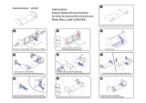
A
C
D
B
E
F
A. Opening height: 540mm min/575 mm
max.
B. Opening width: 350mm min/450mm
max.
C. Mounting depth: 108mm
D. Hearth must extend minimum of
150mm either side of the opening.
E. Hearth must extend minimum of 300mm
in front of the firebed.
F. Non-combustible hearth must be a mini-
mum of 50mm in height, or be surrounded
by 50mm high fender.
G. 470mm: This area must be flat and verti-
cal to allow good frame sealing.
H. 585mm: This area must be flat and verti-
cal to allow good frame sealing.
X. SSee ssection 44.1.
4.0
G
H
X
Maximum ddepth oof sshelf MMinimum ddistance ffrom iinside eedge oof
fire fframe tto uunderside oof sshelf
100mm (4in) 203mm (8in)
150mm (6in) 305mm (12in)
203mm (8in) 356mm (14in)

DEBRIS CCOLLECTION SSPACE
The mounting depth of this appliance is 108mm.
In accordance with BS 5871 part 2, minimum debris collection volumes are required behind the installed appliance. These are shown in the
table below and as dimension X on the fireplace diagram shown previously.
CLAY/CEMENT LLINES OOR BBLOCK FFLUE WWHICH IIS NNEW, UUNUSED, OOR PPREVIOUSLY OONLY UUSED WWITH AA GGAS FFIRE.
X DDimension == 220mm
UNLINED FFLUE OOR CCHIMNEY WWHICH HHAS BBEEN PPREVIOUSLY UUSED FFOR AA SSOLID FFUEL OOR OOIL BBURNING AAPPLIANCE
X DDimension == 660mm
VENTILATION
No ppurpose pprovided vventilation iis nnormally rrequired ffor tthis aappliance
. The requirements of other appliances operating in the same room or
space must be taken into consideration when assessing ventilation.
If spillage is detected when commissioning the appliance, then amongst other problems there may be insufficient natural ventilation for cor-
rect operation of the flue. If the appliance does not spill with the windows open, but spillage is detected with the windows closed, this demon-
strates a lack of natural ventilation. If spillage is still detected with the windows open, the flue is at fault. Installation of an air brick is the best
solution to lack of ventilation. Any ventilation fitted must comply with BS 5871 part 2 and BS 5440 part 2. Vents fitted under or within the
immediate vicinity of the appiance must not be used as adverse effects to the operation of the ODS may occur.
Spillage detected during commissioning is almost always a result of poor flue performance that cannot be corrected by any amount of venti-
lation.
For Republic of Ireland ventilation may be required, see IS 813, ICP3, IS 327, and any other rules in force.
PREFABRICATED FFLUE BBOXES
This appliance can be fitted into a number of proprietary flue boxes provided that the minimum dimensions given in the diagram below are
complied with.
Constructional NNote:
The frame of the fire, any back panel or
other infill panels, and the flue box must be sealed together so
that there is no possibility of leakage between them. Adequate
clearances to combustible materials (e.g. false chimney breast
construction) must be maintained.
The mmanufacturers’ iinstructions ffor ffitting tthe pprefabricated bbox
shall bbe ccomplied wwith aat aall ttimes.
To fit the fire using the cable fixing kit, some minor adaption
may be necessary for certain flue boxes. A check should be
made to ensure the firebox does not obscure the flue box out-
let.
The firebox, base of the flue box, and hearth below may be
drilled to allow plugs and screws to secure installation.
It is important that the sealing requirements of the appliance are
met at all times and that the flue box is well sealed to any back
or infill panel.
Note:
The DEPTH dimension is inclusive of any back or infill
panel.
UNPACKING THE APPLIANCE
Stand the carton the right way up, cut the strapping bands and remove the top endcap. Read
all
the instructions before continuing to unpack
or install this appliance.
Remove the box containing the cast front fret, and the bags containing the coals. Remove the cardboard packing pieces, and any other bags
or boxes containing fittings or other parts. When all loose parts have been removed, the outer sleeve may be lifted off to reveal the appliance.
Check that the components supplied correlate with the component checklist given in section 7.1. Please dispose of all the packaging materi-
als at you local recycling centre.
4
4.0
5.0
125mm min internal
dia twin wall flue
540mm min
opening height
350mm min
opening width
128mm
min depth
6.0
7.0

COMPONENT CCHECKLIST
QUANTITY DESCRIPTION
1 Firebox and burner tray assembly.
1 Decorative frame
1 Cast front fret with seperate ashpan door.
1 Moulded ceramic fibre combustion matrix.
15 Individual ceramic coals.
2 Ceramic fibre side cheeks
1 Ceramic brick panel.
1 Cable fixing kit; 2 cables, 2 tensioners, 2 cable clamps, 4 fixing eyes.
1 Sealing grommet
3 Lengths of adhesive sealing strip.
1 Self tapping screw pack; 4 No8 x 5/16.
1 Deflector baffle
1 Blanking plate plus M4 x 12 screws
1 Set of manufacturers instructions and warranty card.
4 Fibre Rawl Plugs
INSTALLATION OF AAPPLIANCE
Note: EEnsure tthat tthe ggas ssupply iis iisolated bbefore ccommencing iinstallation oof tthe aappliance.
The fireplace opening and environment must be in compliance with specifications laid down in the appropriate sections of these instructions.
PREPARING TTHE AAPPLIANCE
Remove the appliance from it’s carton as described previously and stand on a dust sheet or similar. Place the coals, ceramics and fixings safe-
ly to one side.
Remove the burner from the assembly by removing the two screws in the data/control plate. Lift away the plate, and remove the two screws
retaining the tray legs. The tray is now free and may be lifted away.
Knock out holes are provided in the rear of the convector box for use where concealed pipework is required. Knock out the holes with a
sharp tap from a hammer and fit the rubber grommet supplied. A small incision can now be made in the rubber to slip snugly around the out-
side of the supply pipe and sleeving.
Note: DDO NOT
install or use the appliance without this seal in place.
If the hole is inadvertently opened, reseal with an intact grommet. Failure to
fit this seal correctly will cause the flue suction to act upon the area under the
burner resulting in poor performance.
SPIGOT RESTRICTOR.
If fitting the fire into a Class 1 or good Class 2 flue,
attach the spigot restrictor to the rear of the appliance using screws provided.
If spillage is detected during the commissioning of the appliance, the spigot
restrictor should be removed immediately.
PREPARING TTHE OOPENING
Before installing the fire, check the flue for correct operation using a smoke
pellet. All of the smoke should be drawn up the flue and exit correctly from
the terminal. If problems are found DO NOT fit the fire until corrective action is completed.
Protect the decorative hearth whilst pushing the convector box in and out of the opening. Part of the packaging is an ideal hearth saver pad.
Before running the gas supply into the opening, offer up the convector box to the fireplace to check the fit is good. Ensure that it slides in cor-
rectly, the sealing face sits flat and square to the wall or infill panel, and that the base is firm in the floor of the opening as no leaks are per-
missible here. At this stage it is essential to ensure that the spigot outlet of the fire is not obstructed in any way. Remove the convector box
and take any necessary measurements before making good and preparing for final installation. Apply the self adhesive sealing strips around
the edge of the rear of the firebox frame, approximately 5mm in from the edge.
5
7.1
8.1
8.0
8.2

PREPARING THE OPENING ((continued)
Cable ffixing:
For fixing the fire by the cable method, see relevant section.
Fixing bby sscrew:
Mark and drill the fireframe or base, and relevant points in the opening or on the wall. Rawlplugs will be required. NOTE:
Plastic rawlplugs are not suitable for this application.
Gas ssupply:
Following preparation for the fixing method, the concealed gas supply (if required) can now be put into place. Refer to the rel-
evant section for suggested pipe routes. The ends of the sleeving in which the gas pipe is run should be sealed. The end of the 8mm sup-
ply pipe should be temporarily sealed to prevent the ingress of debris during fixing.
GAS SUPPLY RROUTING
When the opening is ready for installation of the fire, the gas supply can be routed as shown in the following diagrams.
An isolator cock or restrictor elbow must be fitted to the incoming supply to facilitate servicing.
If using a concealed supply it should be laid in accordance with the diagram below. Select the supply route most relevant to the entry
point of the gas supply into the fireplace opening.
If using an across the hearth connection, then the firefront is notched and the supply pipe can be routed through this.
The gas pipe must be suitably protected where it passes through fireplace openings. Any sleeving should be sealed to the pipe at its ends.
The open end of the gas supply pipe should be temporarily sealed to prevent ingress of dust and dirt during installation.
CABLE FIXING
Drill four holes as shown in the diagram and fit the fibre rawl plugs. If the fireplace
does not allow for the exact layout shown, the eyebolts should be fixed to give a sim-
ilar configuration as possible.
Thread both tensioning cables through the holes at the top of the firebox, both eye-
lets, and back through the lower holes in the firebox as shown in the photograph.
Before finally fitting the firebox, apply the self-adhesive sealing strips around the rear
of the firebox frame.
Push the appliance back into the fireplace, centralise and pull the loose cables
through the holes into the firebox.
Thread the cable tensioners onto the cables as shown,
with the nuts screwed down close to the tensioner
head.
Slide the screwed nipple onto the cable, pull cable taut
and tighten nipple.
Adjust tensioner using a suitable spanner to pull the
appliance back into position, to allow an even seal
around the fireplace opening.
Visually inspect the seal and reseat if necessary.
Surplus tension cable MUST NOT be cut off as this will
prevent proper installation after servicing. Coil up the
surplus cable and tuck the coils out of the way as sug-
gested in the photograph.
6
8.2
8.3
Fireplace Opening
Grommets
Firebox
Gas Valve
A. 250mm
B. 350mm
C. 60mm
Dimensions
+/-10mm
A
B
C
Concealed
Over Hearth
8.3
8.4

FITTING THE BURNER TRAY
Imoprtant NNote: CCheck tthe tthermocouple nnut cconnection iinto tthe rrear oof tthe vvalve iis ssecure.
Temporarily fit the burner tray and ensure a suitable gas route can be
achieved. Place the burner tray into the firebox making sure that the rear
lugs locate properly on to the ledge in the firebox. Fit the two securing
screws through the tray legs to secure the assembly.
Connect the gas supply and tighten the gas connections. Fit the data/con-
trol plate to the tray using the two screws provided. Ensure that the con-
trol knob can be pushed fully in and does not touch the plate.
Fit the deflector baffle to the two locations on the front face of the fire-
tray. Screws are provided for this purpose. The baffle should be level with
the lower edge of the tray. Place the front casting in front of the fire tem-
porarily to check the angle of the baffle. The casting should fit well and
the control devices beneath should not be visible to the eye. Realign the
baffle slightly if necessary to achieve the correct fit.
GAS CONNECTION
Purge the gas supply to remove any air, and connect the previously installed gas supply to the control tap and tighten all joints.
If using an across hearth connection ensure the decorative frame and firefront will clear the supply route. If the data/control palte is not
already fitted, attach with two screws, ensuring the control knob is free to
be depressed fully.
FUEL BED LAYOUT
Place the brick panel against the rear of the firebox
Place the ceramic combustion matrix onto the burner and the ceramic side
cheeks onto the matrix.
Place the front row of six coals on to the matrix, with the two coals sec-
ond front each end turned on their sides. Ensure the coals are firmly
against the side cheeks as shown in the photograph. If necessary, pull the
coals forward slightly to ensure their rear edges do not overhang the flame
ports. Corners or rough edges MUST NOT be allowed to enter the flame
ports. If in any doubt pull the coals as far forward as possible.
Place the rear row of four coals, making sure that the flat sides are firmly against
the brick panel and side cheeks as shown.
Place the middle row of five coals onto the flats in the matrix. Ensure the
coals are not put into the holes in the matrix. Place the two end coals firm-
ly against the side cheeks and back to the steps on the matrix, turning them
on to their sides as shown.
Note: TThe ccoals mmust nnot bbe ccrammed ttogether, oor iinserted iinto tthe hholes
in tthe mmatrix. AA wwell llaid oout, ggenerously sspaced ccoal llayout wwill ggive
the bbest rresults.
7
8.5
9.0
8.6

FUEL BED LAYOUT ((continued)
Coals may be rotated slightly within their positions to give a good visual effect.
The edges or corners of the front row of coals MUST NOT be allowed to enter the flame slots in the matrix. If in doubt, pull them forward as
far as possible. Pay special attention to finally adjust the coals with the fire lit on the HIGH setting in order to ensure that no flames play onto
the firebox sides. This will reduce the possiblity of heat discolouration.
The fire is designed to operate correctly with the coals supplied when assembled according to the instructions. Never add to the fifteen coals,
or change them for a different type. Never throw rubbish or other matter onto the coal bed.
FITTING THE DECORATIVE FRAME
The appliance is supplied with a decorative frame.
The frame attaches to the firebox as a three piece clip-on assembly. The side pieces of the clip-on assembly should be pushed into position
first, followed by the top bar, which should overlap the sides. A plastic protective coating may be applied to the face of the frame assembly,
which should be removed at this stage.
IMPORTANT NNOTE: DDue tto tthe ppossiblity oof ssharp eedges, ccare sshould bbe ttaken wwhen hhandling tthe tthree ppiece fframe ccomponents. TThe
use oof pprotective ggloves iis rrecommended.
Place the firefront into position in front of the fire and slide the ashpan door into place. Do not use any other firefront other than the one sup-
plied with this applaince. The firefront shown in these instructions may differ form the one supplied with the appliance.
TESTING AND COMMISSIONING
Turn on and test the gas supply up to the fire for any leaks, in accordance with current Approved Codes of Practice (ACOPs)
OPERATING THE APPLIANCE
The pilot is visible through the left hand side of the matrix. Rotate the coals for good viewing. Push in
and turn the control knob to the SPARK position, and hold there for a few seconds.
Continue turning anti-clockwise through the spark click to the PILOT light position, ensuring the pilot
has lit. If not, return the knob clockwise, and repeat.
When the pilot lights after the spark, keep the knob depressed for approximately ten seconds. Now
release the knob and the pilot should stay alight. If the pilot is extinguished during use, wait three min-
utes before repeating the ignition procedure. To achieve the HIGH setting, push the control knob in
slightly and continue turning anti-clockwise to the high position. The main burner should light after a
few seconds. To decrease the setting to LOW, turn the control knob clockwise to the low setting.
To turn to the PILOT position from the HIGH or LOW positions, press the control knob in, and return
to the pilot position and release. To turn the fire OFF, keep the knob pressed in, return to the off posi-
tion and release.
SPARK FAILURE
The gap between the spark electrode and the pilot should be 3.5 - 4.5mm to produce a good spark. There should be no need to adjust this.
If under any circumstances the electric spark fails, the pilot may be lit manually by proceeding with the ignition sequence as previously
described, and after turning the control knob through the spark position, the knob should be held in and the pilot lit with a taper.
SETTING PRESSURE
Remove the screw from the pressure test point, which will be be situated in one of two loca-
tions:
1) On the main injector pipe (fig.1).
2) On the valve above the control knob (fig2). To access, remove the data plate by the
unscrewing the two screws, as indicated, from the front of the burner assembly. The pressure
test point is situated on the left above the control knob.
Attach a U gauge. Light the fire on the HIGH setting.
The setting pressure should be in accordance with the figures stated on page 2 of these instruc-
tions. The fire is factory set to achieve these pressures and any significant variation could indi-
cate a supply problem.
If the pressure is too high, the gas supply meter may be set incorrectly. This should be checked
with the fire running and if necessary reset by the gas supplier. If the pressure is too low, then
check the meter governor pressure with the appliance running. If this is incorrect it will need to
be reset by the gas supplier.
If the setting pressure is too low, but the meter pressure is acceptable, then a problem in the
supply pipework is to be suspected. This will be dirt and debris, kinked or inadequate size pipes,
restriction in a fitting or solder flashing across a joint.
8
9.0
10.0
11.0
11.1
11.2
12.0
fig1.
fig2.

FLUE SPILLAGE MONITORING SYSTEM
This fire is fitted with a flue spillage safety device (ODS). If the fire shuts down during use for no apparent reason then several things may be
suspected. If a door or window has been opened creating a draught, then pilot disturbance is the problem, and removal of the draught should
resolve this. The gas pressure reaching the fire must also be checked (again, recall your installer to check and rectify any problem). The ther-
mocouple connection into the back of the gas control valve may also have worked loose during installation, simply get the installer to tight-
en.
If pilot disturbance is not the cause, then the ODS safety system may be in operation. Switch the appliance OFF, check the flue and carry out
any remedial work required. Relight the fire and carry out a spillage test. DO NOT allow the appliance to be used if it continues to fail a
spillage test.
The aeration hole of the pilot must be carefully cleaned out on each annual service to ensure continued function of the ODS.
The spillage monitoring system shall not be adjusted, modified, or put out of operation by the installer. Any spare parts fitted MUST be of a
type supplied for the purpose by the appliance manufacturer.
If the fire is not spilling, then further guidance should be sought, using the Troubleshooting section as a guide.
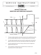
TESTING FOR SPILLAGE
Close all doors and windows to the room containing the appliance. Let the fire run on HIGH for five minutes. Take a smoke match, light it,
and using a smoke match tube, hold it at the top edge of the fire opening, 25mm down and 25mm in. Starting 50mm in from either side, run
the smoke match across the opening. All the smoke should be drawn away up the flue. Any smoke returning into the room indicates that
spillage is occurring. If the initial spillage test fails, run the fire for a further 10 minutes and repeat the test. When the test has been complet-
ed satisfactorily, repeat with any extractor fans in the premises running on the highest setting, and any communicating doors open. Finally,
repeat with all doors open.
DO NOT allow the fire to be used until the test is satsfactorily passed.
BRIEFING TTHE CCUSTOMER
All instructions must be handed to the user for safekeeping. Show the customer how to light and control the fire.
After commissioning the appliance, the customer should be instructed on the safe use of the appliance and the need for regular servicing.
Frequency of service depends on usage, but MUST be carried out at least once annually.
Advise that cleaning of the fire may be achieved when the fire is cold using a damp cloth and mild detergent on most surfaces.
Scratched and other superficial damage to the matt black paintwork of the appliance can be covered with matching heatproof spray. Use
only the manufacturers’ recommended spray paint. Paint only when the fire is OFF and cold. Always mask off the surrounding area to pre-
vent contamination with overspray. Ventilate the room during the use of the spray. DO NOT attempt to spray paint the coals or ceramics,
or wash them in water.
Advise that the fire will emit a “newness” smell for a time after initial commissioning and that extra ventilation may be needed during this
time. Advise that the fire is fitted with a spillage safety device (O.D.S.). If the fire shuts down, this system may be in operation. If spillage is
suspected, SWITCH APPLIANCE OFF and call in the installer to investigate any problems.
9
12.1
13.0
A
B
C
C
Cross section of smoke
match tube
A.25mm down
from top of
opening
B. 25mm in
from front of
opening.
C. Disregard
outer 50mm
either side of
fireplace open-
ing
Crimp
Match
Tube
Take a length of 10mm dia pipe
and seal one end. Crimp the
pipe to prevent the match from
sliding down inside
14.0

SERVICING
Isolate the fire from the gas supply. Ensure that the fire is fully cold before attempting service. A suggested procedure for servicing is detailed
below.
1. Lay out the dust sheet and tools.
2. Carefully remove the ceramic components.
3. Remove the cast front fret.
4. Remove the two screws that retain the data/control plate.
5. Disconnect the gas supply, and remove the two securing screws in the tray legs.
6. Remove the burner tray.
7. Remove convector box as described.
8. Check the fireplace opening for rubble accumulation and remove. If debris is excessive, initiate remedial work on the flue.
9. Check the flue with smoke pellet for correct operation.
10. Refit convector box using new seals where necessary
11. Strip off the burner pipes and clean thoroughly.
12. Clean out the injector, pilot assembly and burner tube. DO NOT remove the pilot injector.
13. Re-assemble and re-fit the burner tray.
14. Turn on the gas supply, and leak test.
15. Refit the decorative casting and ceramics.
16. Check any purpose provided ventilation is un-obstructed.
17. Light the fire and test for spillage.
18. Check setting pressure and safe operation of the appliance.
For specific servicing instructions, see the relevant sections.
CLEANING TTHE CCOALS
Remove the firefront casting and place to one side. Remove the ceramic components. Gently clean in the open air. Be careful not to create
dust from the coals. Where necessary replace damaged components with genuine spares. Seal scrap ceramic components in plastic bags
and dispose at proper refuse sites as directed.
Re-fit the coals by referring to the relevant section of these instructions.
REMOVING THE BURNER TRAY
Remove the decorative front. Remove the ceramics and the data/control plate and place safely aside.
Remove the two screws securing the tray legs to the firebox. Pull tray forward slightly and lift away.
Refitting is the reverse of above, being sure to engage the tray location lugs on the shelf at the rear of the firebox.
DISMANTLING TTHE BBURNER TTRAY
Remove the tray as previously described.
The pilot unit can be removed by withdrawing the tubing nut, the thermocouple nut on the rear of the valve, and the two securing screws,
and lifting away. Remove the tubing nut from the valve end of the pilot pipe, and blow through to dislodge any debris.
Remove the two tubing nuts on the ends of the gas pipe to the injector elbow and blow clear. Release the screw through the supporting leg
and lift assembly clear. The injector pipe can now be checked for debris. Remove the nut retaining the injector elbow. Blow through the elbow
to remove any debris.
The valve is not field serviceable, apart from the pilot filter. Remove the control knob by pulling it forwards, then remove the largest of the
three screws on the face of the valve. Slide the filter out and clean away any debris that may have accumulated. The filter element should also
be blown clean. This component should not require replacement, however if signs of deterioration are evident then a genuine spare part must
be used. If a large amount of debris is present in the filter then the pipework and control should be thoroughly cleaned before re-assembly.
10
15.0
15.1
15.2
15.3

PILOT ASSEMBLY
Remove the burner tray as in relevant section and pilot unit as described.
Clean the pilot assembly with a soft brush and blow through. Check the aeration holes are free of any dirt or lint. Clean thoroughly internal-
ly, the connection can be removed from the base of the pilot unit using two spanners to make cleaning easier. Do not damage or try to
remove the pilot injector.
The unit is factory set and the only check necessary is to ensure the spark gap is correct. See specifications for gap setting.
REMOVING TTHE CCONVECTOR BBOX
Remove the burner tray as described previously.
Protect the hearth from potential damage. Unroll the coiled tensioner cables from the rear of the firebox. Remove the securing nipples and
tensioner adjusters. The firebox is now released from the opening and can be slid outward onto the hearth. Inspect the fireplace opening
for debris and if excessive rectify the flue before proceeding further. Check the seal around the fireframe and if necessary replace. Refitting
of the convector box is as described in the fitting section of these instructions.
TROUBLESHOOTING GGUIDE
Fire ssparks bbut ppilot ddoes nnot llight
No gas to fire, check isolators are open.
Pipework blockage, clean out.
Air not fully purged, repurge supply or wait longer.
Spark earthing to metal work, reset gap correctly.
Blocked pilot, clean out internally.
Pilot llights bbut tthen ggoes oout
Severe restriction in gas supply, clear obstruction.
Faulty thermocouple, replace pilot unit.
Hold control knob in for longer.
Check control knob does not foul data plate.
Missing grommet seal in firebox, replace
Fire ddoes nnot sspark aat ppilot
HT lead detached, refit.
Spark gap too large or small, reset correctly.
Faulty piezo unit, replace.
Debris shorting out electrode, clean.
Spark shorting to metalwork under tray, realign HT lead.
Fire rruns ffor aa ttime aand tthen ccuts ooff
Excessive room draught or flue pull, rectify.
Loose or faulty thermocouple, rectify.
ODS system in operation.
Firebox grommet seal not fitted, rectify.
Lint in pilot aeration hole, clean thoroughly internally
Pilot fflame sshrinks wwhen ffire iis oon hhigh
Poor gas flow to fire, check pressure with fire on high.
If pressure is low, remove any restriction in pipework or valve.
Check all isolators are adequately sized and fully open.
Check meter pressure is adequate.
Air leak under base of firebox, rectify.
Lint in pilot aeration hole, clean thoroughly internally.
Firebox grommet seal missing, rectify
Fire ssmells wwhen ffirst llit oor iin uuse
Newness smell from brand new appliance.
Spillage occurring. Carry out spillage test and rectify any problems.
Low temperature sealants or combustible materials used in incorrect positions.
Air leak under base of firebox, rectify
Firebox grommet seal missing, rectify.
11
15.4
15.5
16.0

USER INSTRUCTIONS
IMPORTANT NNOTES
The installation of this fire MUST only be carried out by a competent person (such as a CORGI registered fitter)
in accordance with the Gas Safety (Installation and Use) Regulations 1998, the relevant British Standards, Codes
of Practice, the Building Regulations and the manufacturers’ instructions.
Failure to comply with the above recommendations could lead to prosecution and invalidate the appliance
warranty.
Please ensure you are handed all of the manufacturers documents on completion of the installation. This will
include these instructions.
Always keep a note of the installer’s name and address, the original purchase receipt and the date of installation
for future reference.
The fire and flue should be serviced regularly to ensure continued safe operation. See the servicing section for
further details. Frequency of service will depend on use, but MUST be carried out at least once annually.
Parts of this appliance become naturally hot during use. It is recommended that a suitable fire guard conforming
to BS 6778 is used, especially where young children, the elderly, or infirm are concerned.
Combustible items, such as flooring and furniture, and soft wall coverings (such as blown vinyl or embossed
paper) may discolour if fitted too close to the fire. See relevant section for further details on clearances to
combustibles. No combustible material or flooring should protrude onto the hearth.
DO NOT burn any foreign material on this fire, the coals must be of the correct type and laid out in accordance
with the relevant section of these instructions. Failure to do so could create a hazard or lead to sooting.
Before the appliance is installed, the chimney should be swept. All flues should be checked by the installer to
ensure there are no defects or obstructions that may prevent the flow of combustion products.
This appliance is fitted with a flue blockage safety device which will shut down the fire if abnormal flue conditions
occur. It is NOT a substitute for an independently mounted Carbon Monoxide detector.
The fire is only suitable for use with the gas type for which it is supplied.
1
Section
1.0
2.0
3.0
4.0
5.0
6.0
7.0
8.0
9.0
Contents
Important Notes
Firefront
Clearances to Combustibles
Ventilation
Operating Instructions
Flue Spillage Monitoring System
Cleaning
Coals and Ceramics
Servicing
Page NNo.
1
2
2
2
2
2
3
3
3
1.0

FIREFRONT
This fire is supplied with a particular style of firefront. Use of the firefront will ensure an adequate airflow under the firebed for the correct
functioning of this appliance.
Compliance with safety standards cannot be guaranteed if another style of front is used.
CLEARANCES TTO CCOMBUSTIBLES
A combustible shelf may be fixed to the wall above the fire, providing that it complies with the dimensions given below.
A non-combustible shelf may be fitted to within 10mm of the top edge of the fireframe.
Combustible materials, such as wood, may be fitted to within 100mm (4in) of either side of the frame of the appliance, providing the for-
ward projection does not exceed 100mm (4in).
Any combustible side walls must be at least 500mm to the side of the radiant heat source.
As with all heating appliances, any decorations, soft furnishings, and wall coverings (i.e. flock, blown vinyl and embossed paper) positioned
too close to the appliance may discolour or scorch.
VENTILATION
No ppurpose pprovided vventilation iis nnormally rrequired ffor tthis aappliance.
The requirements of other appliances operating in the same space
or room, and the results of a spillage test must be taken into consideration when assessing ventilation requirements, this will have been car-
ried out by your CORGI registered installer.
For Republic of Ireland, ventilation may be required, see IS 813, ICP3, IS 327, and any other rules in force.
OPERATING IINSTRUCTIONS
The pilot is visible through the underside of the left hand side of the matrix. Push in and turn the
control knob to the SPARK position, and hold there for a few seconds.
Continue turning anti-clockwise through the spark click to the PILOT light position, ensuring the
pilot has lit. If not, return the knob clockwise, and repeat.
When the pilot lights after the spark, keep the knob depressed for approximately ten seconds. Now
release the knob and the pilot should stay alight. If the pilot is extinguished during use, wait three
minutes before repeating the ignition procedure.
To achieve the HIGH setting, push the control knob in slightly and continue turning anti-clockwise
to the high position. The main burner should light after a few seconds.
To decrease the setting to LOW, turn the control knob clockwise to the low setting.
To turn to the PILOT position from the HIGH or LOW positions, press the control knob in, and return to the pilot position and release.
To turn the fire OFF, keep the knob pressed in, return to the off position and release.
FLUE SSPILLAGE MMONITORING SSYSTEM
This fire is fitted with a flue spillage safety device (ODS). If the fire shuts down during use for no apparent reason then several reasons may
be suspected. If a door or window has been opened creating a draught, then pilot disturbance could be the problem, and removal of the
draught should resolve this. The fire can then be re-lit in accordance with the previous section. A grommet seal may also be missing from the
firebox causing abnormal draught to shut down the pilot. Call your installer to check seals are properly fitted.
If pilot disturbance is not the cause, then the ODS safety system may be in operation. Switch the appliance OFF, call in your installer to check
the flue and ventilation and carry out any remedial work required. DO NOT allow the appliance to be used until the flue system is passed as
safe.
2
2.0
3.0
4.0
5.0
Maximum ddepth oof sshelf MMinimum ddistance ffrom iinside eedge oof
fire fframe tto uunderside oof sshelf
100mm (4in) 203mm (8in)
150mm (6in) 305mm (12in)
203mm (8in) 356mm (14in)
6.0

CLEANING
Before carrying out any of the following operations, ensure that the fire is OFF and completely cold.
Debris that may form on the firebed should be periodically removed by a competent person. Large deposits could indicate deterioration of
the flue. This should be repaired by a competent person, and the fire serviced before further use.
FIREFRONT - Any dust accumulating in the firefront may be removed using a vacuum cleaner or dry cloth. Heavy stains may be removed by
using a damp cloth and mild household detergent. Brass parts of the firefront may be cleaned using a suitable brass cleaner. Replace the front
centrally against the fire after cleaning.
PAINTED AREAS - These can be cleaned using a dry cloth.
COALS AAND CERAMICS
See the relevant section in the Installation Guide of these instructions.
SERVICING
The fire and flue should be checked on an annual basis to ensure all of the product of combustion are entering the flue and that there is no
excessive build up of soot. The frequency of service will depend on usage, but MUST be carried out at least once annually. Servicing must
be carried out by a competent person, such as a CORGI registered installer.
Cleaning of the coals may be carried out by following the instructions given in the Installation section. The Installation instructions carry full
servicing details for the use of the installer.
If debris from the flue or other foreign matter is found on the fire it may indicate a need for servicing. Do not use the fire until the source of
the debris has been found and rectified.
Air vents (where fitted) should be checked periodically to ensure they are free from obstruction.
LIST OF SPARES
PART NNO.ITEM
FT003033/0 Pack of 15 coals
FT003005/0 Ceramic combustion matrix
FB004030/0 Ceramic side cheeks
FB004050/0 Ceramic brick panel
Enquire Decorative Frame
Enquire Decorative Front
3
7.0
8.0
9.0
10.0
/