ESAB ESABFeed 30-2 M11 User manual

Category
Welding System
Type
User manual

This manual is also suitable for

ESAB ESABFeed 30-2 M11 is a wire feed unit designed for MIG/MAG welding applications. It features a 2-wheel drive wire feed mechanism and control electronics, enabling precise wire feeding and welding control. With adjustable wire feed speed, burnback time, creep start, and 2/4 stroke settings, the ESABFeed 30-2 M11 offers versatility for different welding tasks. It can accommodate wire bobbins up to 300 mm in diameter and handles wire dimensions from 0.6 to 1.2 mm. The compact design and IP23 enclosure rating make it suitable for both indoor and outdoor use.

ESAB ESABFeed 30-2 M11 is a wire feed unit designed for MIG/MAG welding applications. It features a 2-wheel drive wire feed mechanism and control electronics, enabling precise wire feeding and welding control. With adjustable wire feed speed, burnback time, creep start, and 2/4 stroke settings, the ESABFeed 30-2 M11 offers versatility for different welding tasks. It can accommodate wire bobbins up to 300 mm in diameter and handles wire dimensions from 0.6 to 1.2 mm. The compact design and IP23 enclosure rating make it suitable for both indoor and outdoor use.

GB
Valid for serial no. 238--xxx--xxxx, 410--xxx--xxxx,
440--xxx--xxxx
0459 206 001 GB 041101
ESABFeed 30- 2 M11
Instruction manual
-- 2 --
TOCe
Rights reserved to alter specifications without notice.
1 DIRECTIVE 3........................................................
2SAFETY 3...........................................................
3 INTRODUCTION 4...................................................
3.1 Equipment 5................................................................
4 TECHNICAL DATA 5.................................................
5 INSTALLATION 6....................................................
5.1 Lifting instructions 6.........................................................
6 OPERATION 7.......................................................
6.1 Connections and control devices 8............................................
6.2 Water connection 8..........................................................
6.3 Function explanations 8......................................................
6.4 Wire feed pressure 9........................................................
6.5 Changing / loading wire 10....................................................
6.6 Chaning feed roller 10........................................................
7 MAINTENANCE 10....................................................
7.1 Inspection and cleaning 10....................................................
8 ORDERING SPARE PARTS 11..........................................
DIAGRAM 12............................................................
ORDERING NUMBER 13.................................................
WEAR COMPONENTS 14.................................................
ACCESSORIES 16.......................................................
-- 3 --
bm36d1ea
1DIRECTIVE
DECLARATION OF CONFORMITY
ESAB Welding Equipment AB, S--695 81 Laxå, Sweden, declares that Wire feed unit ESABFeed
30--2
M11 from serial number 238 onwards, conforms to standard EN 60974--5, in accordance with the
requirements of directive (73/23/EEC) and appendix (93/68/EEC) and standard EN 50199 in accord-
ance with the requirements of directive (89/336/EEC) and appendix (93/68/EEC).
-- -- -- -- -- -- -- -- -- -- -- -- -- -- -- -- -- -- -- -- -- -- -- -- -- -- -- -- -- -- -- -- -- -- -- -- -- -- -- -- -- -- -- -- -- -- -- -- -- -- -- -- -- -- -- -- -- -- -- -- -- -- -- --------
Henry Selenius
Vice President
ESAB Welding Equipment AB
695 81 LAXÅ
SWEDEN Tel: + 46 584 81000 Fax: + 46 584 411924
Laxå 2003--02--10
2SAFETY
Users of ESAB welding equipment have the ultimate responsibility for ensuring that anyone who
works on or near the equipment observes all the relevant safety precautions. Safety precautions
must meet the requirements that apply to this type of welding equipment. The following recommen-
dations should be observed in addition to the standard regulations that apply to the workplace.
All work must be carried out by trained personnel well--acquainted with the operation of the welding
equipment. Incorrect operation of the equipment may lead to hazardous situations which can result
in injury to the operator and damage to the equipment.
1. Anyone who uses the welding equipment must be familiar with:
S its operation
S location of emergency stops
S its function
S relevant safety precautions
S welding
2. The operator must ensure that:
S no unauthorized person is stationed within the working area of the equipment when it is
started up.
S no--one is unprotected when the arc is struck
3. The workplace must:
S be suitable for the purpose
S be free from drafts
4. Personal safety equipment
S Always wear recommended personal safety equipment, such as safety glasses, flame--proof
clothing, safety gloves.
S Do not wear loose--fitting items, such as scarves, bracelets, rings, etc., which could become
trapped or cause burns.
5. General precautions
S Make sure the return cable is connected securely.
S Work on high voltage equipment may only be carried out by a qualified electrician.
S Appropriate fire extinquishing equipment must be clearly marked and close at hand.
S Lubrication and maintenance must not be carried out on the equipment during operation.
GB
-- 4 --
bm36d1ea
WARNING
READ AND UNDERSTAND THE INSTRUCTION MANUAL BEFORE INSTALLING OR OPERATING.
ARC WELDING AND CUTTING CAN BE INJURIOUS TO YOURSELF AND OTHERS. TAKE PRECAU-
TIONS WHEN WELDING. ASK FOR YOUR EMPLOYER’S SAFETY PRACTICES WHICH SHOULD BE
BASED ON MANUFACTURERS’ HAZARD DATA.
ELECTRIC SHOCK -- Can kill
S Install and earth the welding unit in accordance with applicable standards.
S Do not touch live electrical parts or electrodes with bare skin, wet gloves or wet clothing.
S Insulate yourself from earth and the workpiece.
S Ensure your working stance is safe.
FUMES AND GASES -- Can be dangerous to health
S Keep your head out of the fumes.
S Use ventilation, extraction at the arc, or both, to take fumes and gases away from your breathing zone
and the general area.
ARC RAYS -- Can injure eyes and burn skin.
S Protect y our eyes and body. Use the correct welding screen and filter lens and wear protective
clothing.
S Protect bystanders with suitable screens or curtains.
FIRE HAZARD
S Sparks (spatter) can cause fire. Make sure therefore that there are no inflammable materials nearby.
NOISE -- Excessive noise can damage hearing
S Protect y our ears. Use earmuffs or other hearing protection.
S Warn bystanders of the risk.
MALFUNCTION -- Call for expert assistance in the event of malfunction.
PROTECT YOURSELF AND OTHERS!
ESAB can provide you with all necessary welding protection an d accessories.
WARNING!
Read and understand the instruction manual before installing
or operating.
This product is solely intended for arc welding.
3 INTRODUCTION
The ESABFeed 30--2 wire feed unit with control panel
M11 is intended for MIG/MAG--welding together with step
controlled welding power sources.
They come in different variants, see the spare parts list on
page 13.
The wire feed units are sealed and contain two--wheel
drive wire feed mechanisms as well as control electronics.
They can be used together with wire on ESAB’s
MarathonPact, or on wire bobbin (standard Ø 300 mm, accessory Ø 440 mm).
GB
-- 5 --
bm36d1ea
The wire feed unit can be installed either at the power source, suspended above the
workplace, on a support arm or on the floor with or without wheel set.
ESAB’s accessories for t he product can be found on page 16.
3.1 Equipment
The ESABFeed 30--2 wire feed unit is supplied with:
S Instruction manual
S Stickers with recommended wear parts.
4 TECHNICAL DATA
ESABFeed 30--2 M1 1
Power supply 42 V 50 -- 60 Hz
Power requirement 150 VA
Motor current I
max
3.5 A
Settings data
Wire feed speed
Burnback time
Creep start
2/4 stroke
1.9--20.0 m/min
0-- 0.5 s
OFF or ON
2strokeor4stroke
Welding gun connection EURO
Max. diameter wire bobbin 300 mm (*440mm)
Wire dimension 0.6--1.2 mm
Weight 14.3 kg
Dimensions (l x w x h) 690 x 275 x 420 mm
Shielding gas
max pressure
All types intended for MIG/MAG welding
5 bar
Coolant
max pressure
50% water / 50% glycol
5 bar
Permissible load at
35% duty cycle
400 A
Enclosure class
with wire bobin *440mm
IP23
IP2X
* Accessory, see page 16.
Duty cycle
The duty cycle refers to the time as a percentage of a ten--minute period that you can weld at a cer-
tain load without overloading.
Enclosure class
The IP code indicates the enclosure class, i. e. the degree of protection against penetration by solid
objects or water. Equipment marked IP23 is designed for indoor and outdoor use.
Equipment marked IP2X is designed for indoor use.
GB
-- 6 --
bm36d1ea
5 INSTALLATION
The installation must be execu ted by a p rofession al.
WARNING!
This product is intended for industrial use. In a domestic environment this product may cause radio
interference. It is the user’ s responsibility to take adequate precautions.
WARNING!
When welding in an environment with increased electrical danger , only power sources intended
for this environment may be used. These power sources are marked with the symbol .
5.1 Lifting instructions
Ordering number for the lifting eye can be found on page 16.
Note! If another mounting device is used, this should be insulated from the wire feed
unit.
GB
-- 7 --
bm36d1ea
6OPERATION
General safety regulations for the handling of the equipment can be found on
page 3. Read through before you start using the equipment!
WARNING!
Assure that the side panels are closed during operation.
To prevent the reel from sliding off the hub: Lock the reel in place by
turning the red knob as shown on the warning label attached next to
the hub.
WARNING!
WARNING!
Rotating parts can cause injury, take great care.
WARNING!
There is a risk of tipping if the wire feed unit is fitted with a counterbalance arm. Secure the
equipment, especially if used on an uneven or sloping surface.
When moving the equipment use intended handle. NOTE! Never pull on the gun.
GB
-- 8 --
bm36d1ea
6.1 Connections and control devices
1 Knob for setting burnback time 7 Connection for welding gun
2 Switch for creep start OFF / ON 8 Connection for welding current from power
source, (OKC)
3 Knob for setting wire feed speed. 9 Connection for control cable from power
source
4 Switch for 2--stroke / 4--stroke 10 Connection RED for cooling water to po-
wer source (cooling unit)
5 Connection BLUE, with ELP* for cooling
water to the welding gun
11 Connection BLUE for cooling water from
power source (cooling unit)
6 Connection RED for cooling water from
welding gun
12 Connection for shielding gas
NOTE! Cooling water connections only available on certain models.
* ELP = ESAB Logic Pump, see point 6.2.
6.2 Water connection
When connecting a water--cooled welding gun, the power source’s main power
supply switch must be in the Off position and the cooling unit switch must be in
position “ELP/0”.
The wir e feed unit with water connection is equipped with a detection system ELP
(ESAB Logic Pump) which checks that the water hoses are connected. When
connecting a water--cooled welding gun, the water pump starts.
Detection only works with power sources that are equipped with ELP.
6.3 Function explanations
Burnback time
Burnback time is a delay between the time when the wire starts to brake until the
time when the power source switches off the welding voltage. Too short burnback
GB
-- 9 --
bm36d1ea
time results in a long wire stickout after completion of welding, with a risk of the wire
being caught in the solidifying weld pool. Too long a burnback time results in a
shorter stickout, with increased risk of the arc striking back to the contact tip.
Creep start
Creep start means that the wire is fed at low speed until it comes into electrical
contact with the workpiece and then the speed increases to the set speed.
2stroke
With 2 stroke, the gas flow and wire feed start when the trigger switch is pressed in
and end when it is released.
4stroke
With 4 stroke, the gas flow starts when the trigger switch is pressed in and the wire
feed starts when it is released. T he welding process continues until the switch is
pressed in again, the wire feed stops and when the switch is released the gas stops
flowing.
Wire feed speed
This sets the required feed speed of the filler wire in m /minute.
6.4 Wire feed pressure
Start by making sure that the wire moves smoothly through the wire guide. Then
set the pressure of the wire feeders pressure rollers. It is important that the
pressure is not too great.
Fig 1 Fig 2
To check that the feed pressure is set correctly, you can feed out the wire against
an insolated object, e.g. a piece of wood.
When you hold the gun approx. 5 mm from the piece of wood (fig. 1) the feed
rollers should slip.
If you hold the gun approx. 50 mm from the piece of wood, the wire should be
fed out and bend (fig. 2).
GB
-- 1 0 --
bm36d1ea
6.5 Changing / loading wire
S Open the side panel.
S Disconnect the pressure sensor by folding it backwards, the pressure rollers
slide up.
S Straighten out the new wire 10--20 cm. F ile away burrs and sharp edges from the
end of the wire before inserting it into the wire feed unit.
S Make sure that the wire goes properly into the feed rollers track and into the
outflow nozzle or wire guide.
S Secure the pressur e sensor.
S Close the side panel.
6.6 Chaning feed roller
S Open the side panel.
S Disconnect the pressure sensor (1) by folding it
backwards, the pressure rollers slide up.
S Completely undo the socket head cap screw
(2) in the centre.
S Remove the washer.
S Completely undo the two outer socket head cap screws
(3).
S Pull out the feed rollers (4).
During installation, repeat the above in the reverse order.
Choice of tracks in th e feed roller
Turn the feed roller with the dimensioning mark for the required track towards you.
7 MAINTENANCE
Regular maintenance is important for safe, reliable operation.
Note!
All guarantee undertakings from the supplier cease to apply if the customer himself
attempts any work in the product during the guarantee period in order to rectify any
faults.
7.1 Inspection and cleaning
Wire feed unit
Check regularly that the wire feed unit is not clogged with dirt.
S Cleaning and replacement of the wire feed unit mechanism’s worn parts should
take place at regular intervals in order to achieve trouble--free wire feed. Note
that if pre--tensioning is set too hard, this can result in abnormal wear on the
pressure roller, feed roller and wire guide.
GB
-- 1 1 --
bm36d1ea
The brake hub
The hub is adjusted when delivered, if
readjustment is required, follow the instructions
below. Adjust the brake hub so that wire is slightly
slack when wire feed stops.
S Adjusting the braking torque:
S Turn the red handle to the locked position.
S Insert a screwdriver into the springs in the hub.
Turn the springs clockwise to reduce the braking torque
Turn the springs counterclockwise to increase the braking torque. NB: Turn
both springs through the same amount.
Weldin g gu n
S Cleaning and replacement of the welding gun’s wear parts should take place at
regular intervals in order to achieve trouble--free wire feed. Blow the wire guide
clean regularly and clean the contact tip.
8 ORDERING SPARE PARTS
ESABFeed 30--2 is designed and tested in accordance with the international and Euro-
pean standards IEC/EN 60974--5 and EN 50199. It is the obligation of the service unit
which has carried out the service or repair work to make sure that the product still
conforms to the said standard.
Spare parts may be ordered through your nearest ESAB dealer, see the last page of
this publication.
GB
Diagram
-- 1 2 --
bm36e11a
ESABFeed 30- 2 M11
Edition 041 101
Ordering number
-- 1 3 --
bm36o11a
1.
Wa te r cooling kit Feeder with capsuled bobbin
ESABFeed 30--2 0459 116 781
ESABFeed 30--2 x 0459 116 791
Spare parts list 0459 206 990
Edition 041 101
Wear components
-- 1 4 --
bm36whk1
S= Standard
Item
Ordering no. Denomination Wire type Groove
type
Wire dimensions Notes
HK1 0455 889 001* Insert tube (S) Fe, Ss & cored
0455 894 001* Insert tube Al
HK2 0455 886 001* Outlet nozzle (S) Fe, Ss & cored
0455 885 001* Outlet nozzle Al
HK3 0369 716 001 Feed roller geared (S)
HK4 0369 557 001 Feed roller Fe , Ss & cored V Ø0.6--0.8mm
0369 557 002 Feed roller Fe , Ss & cored V Ø0.8--1.0mm
0369 557 003 Feed roller (S) Fe , Ss & cored V Ø 1.0/1.2 & 1.4/1.6 mm
0369 557 004 Feed roller Cored V--Knurled Ø1.0--1.2mm
0369 557 011 Feed roller Al U Ø0.8--0.9mm
0369 557 006 Feed roller Al U Ø1.0--1.2mm
HK5 0193 104 002 Washer
HK6 0455 898 001
0215 201 202
Screw
O--ring
(M5x12)
HK7 0455 881 001 Cover plate
HK8 Screw M4x12
HK9 Screw M3x16
HK10 0466 074 001 Insert tube
HK11 0369 728 001 Pressure roller (S) Flat
0466 262 001 Pressure roller Knurled
HK12 0455 053 880 Geared adapter
HK13 Locking washer SGA D 8
HK14 Holder
HK15 Shaft
HK16 0455 896 001 Spring
HK17 Nut M10
HK18 0458 748 002 Insulating washer
HK19 0458 748 001 Insulating bushing
HK20 0156 602 001
0332 318 001
Inlet nozzle (S)
Inlet nozzle
Fe, Ss, Al & Cored
Fe, Ss & Cored
Ø 2 mm plastic for 0.6--1.6 mm
Ø 2.4 mm steel for 1.2--2.0 mm
HK21 0191 496 114 Woodruf f wedge
* Insert tube 0455 889 001 and outlet nozzle 0455 886 001 must be used together.
Insert tube 0455 894 001 and outlet nozzle 0455 885 001 must be used together.
PARTS SET
Item Ordering no. Denomination Notes
HK100 0469 833 880 Pressure arm complete Includes items HK11 (flat pressure roller), HK12, HK13, HK14 and HK15
Welding with aluminium wire
In order to weld with aluminium wire, proper rollers, nozzles and liners for aluminium wire MUST be
used, It is recommended to use 3 m long welding gun for aluminium wire, equipped with appropriate
wear parts.
Edition 041 101
-- 1 5 --
bm36whk1
Edition 041 101
ESABFeed 30- 2 M11
Accessories
-- 1 6 --
bm36a11a
1 Bobbin cover, plastic 18 kg Ø 300mm ...... 0458 674 880
1 Bobbin cover, metal 18 kg Ø 300mm ....... 0459 431 880
1
2
Bobbin holder ...........................
Adapter for 5 kg bobbin ....................
0458 704 880
0455 410 001
1 Adapter for 440 mm bobbin ................ 0459 233 880
1
2
Lifting eye ...............................
Quick connector MarathonPact ...........
0458 706 880
F102 440 880
Edition 041 101
ESABFeed 30- 2 M11
-- 1 7 --
bm36a11a
1
2
3
Turning piece ............................
Guide pin ................................
Quick connector MarathonPact ...........
0458 703 880
0156 654 883
F102 440 880
1 Wheel kit ................................ 0458 707 880
1 Strain relief for welding gun .............. 0457 341 881
Strain relief bracket for connection set .... 0459 234 880
Push button for cold wire feed or gas purging 0459 465 880
Edition 041 101
ESABFeed 30- 2 M11
-- 1 8 --
bm36a11a
Counter balance device ..................
(includes mast and counter balance)
0458 705 880
Feeder stand . ........................... 0458 522 880
Edition 041 101
ESABFeed 30- 2 M11
-- 1 9 --
bm36a11a
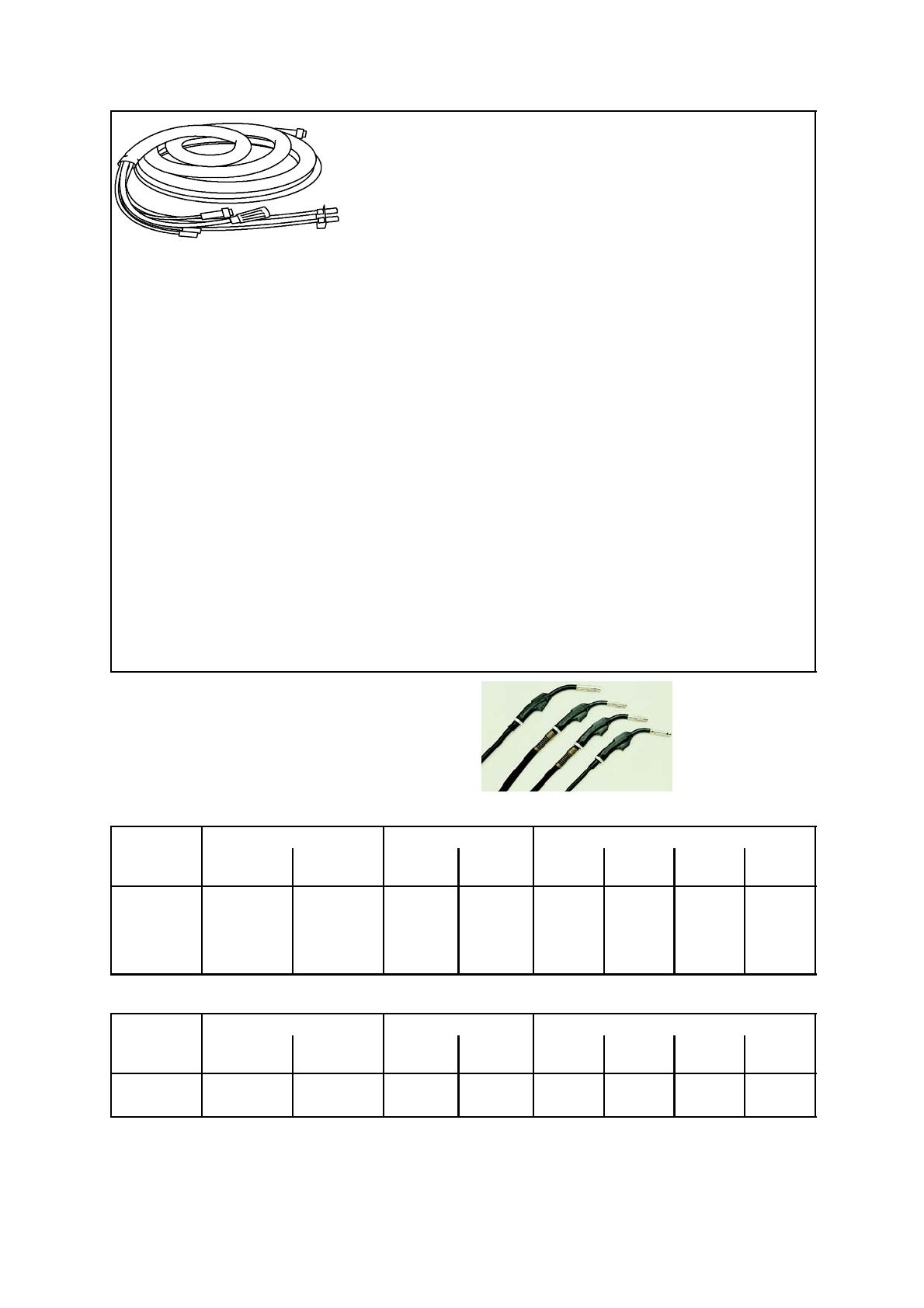
Connection set for 400 A power sources
1.7m ....................................
5m......................................
10m.....................................
15m.....................................
25m.....................................
35m.....................................
1.7m,water ..............................
5m,water................................
10m,water...............................
15m,water...............................
25m,water...............................
35m,water...............................
0469 836 880
0469 836 981
0469 836 881
0469 836 882
0469 836 883
0469 836 884
0469 836 885
0469 836 983
0469 836 886
0469 836 887
0469 836 888
0469 836 889
Connection set for 500 A power sources
1.7m ....................................
10m.....................................
15m.....................................
25m.....................................
35m.....................................
1.7m,water ..............................
10m,water...............................
15m,water...............................
25m,water...............................
35m,water...............................
0469 836 890
0469 836 891
0469 836 892
0469 836 893
0469 836 894
0469 836 895
0469 836 896
0469 836 897
0469 836 898
0469 836 899
Weld ing gu n with EURO connection
Self cooled
Type Ordering no. Max welding current Wire dimensions
Hose length
3m
Hose length
4.5 m
CO
2
Mix Ar Fe Ss Cored Al
PSF 250 0368 100 882 0368 100 883 250A 60% 225A 60% 0.6 -- 1.0 0.6 -- 1.0 1.0 1.0
PSF 305 0458 401 880 0458 401 881 315A 60& 285A 60% 0.8 -- 1.2 0.8 -- 1.2 1.0 -- 1.2 1.0 -- 1.2
PSF 405 0458 401 882 0458 401 883 380A 60% 325A 60% 0.8 -- 1.6 0.8 -- 1.2 1.0 -- 1.6 1.0 -- 1.6
PSF 505 0458 401 884 0458 401 885 475A 60% 410A 60% 1.0 -- 2.4 1.0 -- 1.6 1.0 -- 2.4 1.2 -- 2.4
Water cooled
Type Ordering no. Max welding current Wire dimensions
Hose length
3m
Hose length
4.5 m
CO
2
Mix Ar Fe Ss Cored Al
PSF 410W 0458 400 882 0458 400 883 425A 100% 400A 100% 0.8 -- 1.6 0.8 -- 1.2 1.0 -- 1.6 1.0 -- 1.6
PSF 510W 0458 400 884 0458 400 885 500A 100% 440A 100% 1.0 -- 2.4 1.0 -- 1.6 1.0 -- 2.4 1.2 -- 2.4
ESAB AB
SE--695 81 LAXÅ
SWEDEN
Phone +46 584 81 000
www.esab.co m
031021
ESAB subsidiaries and representative offices
Europe
AUSTRIA
ESAB Ges.m.b.H
Vienna--Liesing
Tel: +43 1 888 25 11
Fax: +43 1 888 25 11 85
BELGIUM
S.A. ESAB N.V.
Brussels
Tel: +32 2 745 11 00
Fax: +32 2 726 80 05
THE CZECH REPUBLIC
ESAB VAMBERK s.r.o.
Prague
Tel: +420 2 819 40 885
Fax: +420 2 819 40 120
DENMARK
Aktieselskabet ESAB
Copenhagen-- Valby
Tel:+4536300111
Fax:+4536304003
FINLAND
ESAB Oy
Helsinki
Tel: +358 9 547 761
Fax: +358 9 547 77 71
FRANCE
ESAB France S.A.
Cergy Pontoise
Tel:+33130755500
Fax:+33130755524
GERMANY
ESAB GmbH
Solingen
Tel: +49 212 298 0
Fax: +49 212 298 204
GREAT BRITAIN
ESAB Group (UK) Ltd
Waltham Cross
Tel: +44 1992 76 85 15
Fax: +44 1992 71 58 03
ESAB Automation Ltd
Andover
Tel: +44 1264 33 22 33
Fax: +44 1264 33 20 74
HUNGARY
ESAB Kft
Budapest
Tel:+3612044182
Fax:+3612044186
ITALY
ESAB Saldatura S.p.A.
Mesero (Mi)
Tel:+3902979681
Fax:+390297289181
THE NETHERLANDS
ESAB Nederland B.V.
Utrecht
Tel: +31 30 248 59 22
Fax: +31 30 248 52 60
NORWAY
AS ESAB
Larvik
Tel:+4733121000
Fax:+4733115203
POLAND
ESAB Sp.z.o.o
Warszaw
Tel: +48 22 813 99 63
Fax: +48 22 813 98 81
PORTUGAL
ESAB Lda
Lisbon
Tel: +351 1 837 1527
Fax: +351 1 859 1277
SLOVAKIA
ESAB Slovakia s.r.o.
Bratislava
Tel:+421744882426
Fax:+421744888741
SPAIN
ESAB Ibérica S.A.
Alcobendas (Madrid)
Tel: +34 91 623 11 00
Fax: +34 91 661 51 83
SWEDEN
ESAB Sverige AB
Gothenburg
Tel:+4631509500
Fax:+4631509222
ESAB International AB
Gothenburg
Tel:+4631509000
Fax:+4631509360
SWITZERLAND
ESAB AG
Dietikon
Tel: +41 1 741 25 25
Fax: +41 1 740 30 55
North and South America
ARGENTINA
CONARCO
Buenos Aires
Tel: +54 11 4 753 4039
Fax: +54 11 4 753 6313
BRAZIL
ESAB S.A.
Contagem-- MG
Tel: +55 31 3369 4333
Fax: +55 31 3369 4440
CANADA
ESAB Group Canada Inc.
Missisauga, Ontario
Tel: +1 905 670 02 20
Fax: +1 905 670 48 79
MEXICO
ESAB Mexico S.A.
Monterrey
Tel: +52 8 350 5959
Fax: +52 8 350 7554
USA
ESAB Welding & Cutting Products
Florence, SC
Tel: +1 843 669 44 11
Fax: +1 843 664 44 58
Asia/Pacific
CHINA
Shanghai ESAB A/P
Shanghai
Tel: +86 21 6539 7124
Fax: +86 21 6543 6622
INDIA
ESAB India Ltd
Calcutta
Tel: +91 33 478 45 17
Fax: +91 33 468 18 80
INDONESIA
P.T. Esabindo Pratama
Jakarta
Tel: +62 21 460 01 88
Fax: +62 21 461 29 29
MALAYSIA
ESAB (Malaysia) Snd Bhd
Selangor
Tel: +60 3 703 36 15
Fax: +60 3 703 35 52
SINGAPORE
ESAB Singapore Pte Ltd
Singapore
Tel: +65 861 43 22
Fax: +65 861 31 95
ESAB Asia/Pacific Pte Ltd
Singapore
Tel: +65 861 74 42
Fax: +65 863 08 39
SOUTH KOREA
ESAB SeAH Corporation
Kyung--Nam
Tel: +82 551 289 81 11
Fax: +82 551 289 88 63
UNITED ARAB EMIRATES
ESAB Middle East
Dubai
Tel: +971 4 338 88 29
Fax: +971 4 338 87 29
Representative offices
BULGARIA
ESAB Representative Office
Sofia
Tel/Fax: +359 2 974 42 88
EGYPT
ESAB Egypt
Dokki--Cairo
Tel: +20 2 390 96 69
Fax: +20 2 393 32 13
ROMANIA
ESAB Representative Office
Bucharest
Tel/Fax: +40 1 322 36 74
RUSSIA--CIS
ESAB Representative Office
Moscow
Tel:+70959379820
Fax: +7 095 937 95 80
ESAB Representative Office
St Petersburg
Tel:+78123254362
Fax: +7 812 325 66 85
Distributors
For addresses and phone
numbers to our distributors in
other countries, please visit our
home page
www.esab.co m
  • Page 1 1
  • Page 2 2
  • Page 3 3
  • Page 4 4
  • Page 5 5
  • Page 6 6
  • Page 7 7
  • Page 8 8
  • Page 9 9
  • Page 10 10
  • Page 11 11
  • Page 12 12
  • Page 13 13
  • Page 14 14
  • Page 15 15
  • Page 16 16
  • Page 17 17
  • Page 18 18
  • Page 19 19
  • Page 20 20

ESAB ESABFeed 30-2 M11 User manual

Category
Welding System
Type
User manual
This manual is also suitable for

ESAB ESABFeed 30-2 M11 is a wire feed unit designed for MIG/MAG welding applications. It features a 2-wheel drive wire feed mechanism and control electronics, enabling precise wire feeding and welding control. With adjustable wire feed speed, burnback time, creep start, and 2/4 stroke settings, the ESABFeed 30-2 M11 offers versatility for different welding tasks. It can accommodate wire bobbins up to 300 mm in diameter and handles wire dimensions from 0.6 to 1.2 mm. The compact design and IP23 enclosure rating make it suitable for both indoor and outdoor use.

Ask a question and I''ll find the answer in the document

Finding information in a document is now easier with AI