Page is loading ...

1-800-255-5387 • www.premier-mfg.com
premier manufacturing company
Page 1
THE FIRST NAME IN QUALITY COUPLINGS
890L & 890CL SERVICE GUIDELINES
BEFORE GETTING STARTED:
► This procedure should only be performed by a
qualified mechanic.
► Tools required: Snap ring pliers, flat-bladed screw
driver, 1/8” allen wrench, 1 1/4” socket, small
hammer.
► CAUTION: When removing and replacing snap rings
the appropriate snap ring plier tools are necessary.
Do not attempt removal or replacement without the
correct snap ring plier tools. In addition, use caution
when removing and replacing snap rings – Do not
over-expand them as damage could result. Also,
when assembling a snap ring into position - Make
certain that the snap ring is fully seated into the
groove.
► Safety glasses are required for all of the following
procedures.
► Prior to disassembly, familiarize yourself with the
location of all the various parts in the coupling. This
will assist in the assembly process.
► See the attached Image Reference Section to
identify the various product parts as well as the noted
positions (i.e. TOP, BOTTOM, FRONT & BASE) of
the coupling body. This will assist in the assembly
process.
DISASSEMBLY
1) As stated above, take a few moments to view the
coupling’s components and their respective positions,
prior to proceeding with disassembly.
2) Place the coupling on a flat work surface, with
mounting base down, pintle hook pointing away from
you with the handles on the left side. Remove the
891P Pin from the 891 Handle.
3) Place the coupling’s latch system in the opened
position by rotating the 896 Handle clockwise until it
stops. While holding the 896 Handle in the maximum
rotated position, grasp and rotate the 891 Handle
clockwise to full rotation, then release 896 Handle.
The 896 Handle should hold the 891 Handle from
rotating back to its previous position.
4) Remove one of the 894Z-1 Snap Rings that secure
the 894 Pin. While holding the 892 Hook, push
the 894 Pin out and then remove the 892 Hook.
If the 894 Pin is stuck, use a brass pin or other
soft material to tap it out. Do not ever strike any
components with steel pins or hammers.
5) Measure the wear area on the pintle horn of the
892 Hook. If the wear is at or exceeds 20% of the
cross section, the coupling is to be considered Out of
Service.
6) Keep clear of the 891 Handle’s rotational space (as it
will release quickly), and rotate the 896 Handle until
the 891 Handle assembly is released.
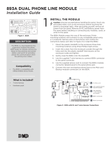
7) Prior to further disassembly, position the coupling
(see Image #2, Fig. 2) with the topside facing down
onto work surface and view the latch & spring
components in particular, noting their respective
positions. This will be helpful for proper reassembly.
8) Reposition the coupling with mounting base down,
pintle hook if in place would be pointing away
from you, and the handles are on the left side, as
previously described. Remove the 387 Locknut
which secures 891 Handle.
9) Using a brass or other soft material as a punch, tap
on the center of the threaded end of the 891 Handle,
to free it from the tapered seats in the 893 Pawl and
remove it from the coupling body. Note: When the
891 Handle is removed; the 893 Pawl, 893A Spring,
and 891C Bushing are also free to be removed. If
necessary you can now remove the 895Z-1 Snap
Ring that resides on the handle end of the 891
Handle.
10) Remove the 275-50 Snap Ring from the end of the
896 Handle.
11) Position coupling body with the topside facing down
onto work surface (see Image #2, Fig. 2 bottom
view). Remove the 895C Set Screw that secures
the 895 Latch to the 896 Handle. Grasp 896 Handle
and pull sideways, removing it from the body. When
the 896 Handle is removed, the 895 Latch and 895A

1-800-255-5387 • www.premier-mfg.com
premier manufacturing company
Page 2
Spring are also free to be removed. Please note that
Thread Locker is used to secure the 895C Set Screw.
Therefore, it may be necessary to slightly heat-up the
part with a torch, in order to remove the set screw.
CAUTION: Do Not to apply heat to the 895A Spring
or permanent damage will occur.
12) If the 891P Pin & Cable are damaged, you can
now remove them. Using a chisel or flat-bladed
screwdriver placed at the base of the 16DS Drive
Screw, tap with a hammer to wedge the 16DS up and
out of the hole it resides in, and remove the 891P Pin
& Cable.
13) Disassembly is now complete. Clean and inspect
parts and body for wear and/or damage. If wear
exists or damage is noted, replace affected
part. NEVER ATTEMPT WELD REPAIR OF ANY
DAMAGED OR WORN COMPONENT.
DISASSEMBLY IS COMPLETE
IMPORTANT NOTES TO CLEAN,
INSPECT & LUBRICATE:
► Use only genuine PREMIER replacement parts on
any repairs. Use of other parts, which can have
different specifications or tolerances, may fail to alert
you to non-obvious damage to the hitch which can
lead to hitch failure.
► All body holes, part holes and pins need to be
thoroughly cleaned and lubricated with a heavy
grease before the parts are reassembled. If a bushing
resides in a part, lubricate the hole prior to installing
the bushing. (DO NOT LUBRICATE PINTLE HOOK
WEAR SURFACE).
► Clean, inspect and lubricate latch components
every 90 days or sooner if required by the operating
environment.
► Clean and inspect the coupling for damage and
excessive wear prior to each and every use.
► Do not over-tighten fasteners as this may cause
damage.
ASSEMBLY
1) With the coupling body positioned on its topside as
shown in Image #2, Fig. 2. Slide the 896 Handle into
the body from the left side until 1/4” of the handle is
protruding past the inside surface of the body.
2) Place 895 Latch into position on the end of the 896
Handle and slide 896 Handle until flush with the
opposite face surface of the 895 Latch.
3) Place the 895A Spring into position on the right
side of the 895 Latch with the straight spring leg
pointing towards you (see Image #2, Fig. 2 for
spring position). While holding the 895A Spring
in alignment, slide the 896 Handle thru the spring
and out the right side of the body until the snap ring
groove is exposed.
4) Locate counter-drilled hole in 896 Handle and align
it with the tapped hole in 895 Latch. Install 895C Set
Screw into 895 Latch, making certain it maintains
alignment with 896 Handle counter-drilled hole, and
then tighten in position. 895C Set Screw should
be flush with the surface of the 895 Latch. If it is
protruding, it is not aligned with the counter-drilled
hole in the 896 Handle. (See Image #2, Fig. 4 for
approx. handle position when completed.) Use a
permanent thread locker to secure the 895C Set
Screw.
5) Rotate the 896 Handle clockwise checking for spring
resistance. If the 895A Spring is installed correctly,
a smooth increasing spring resistance should be felt
when handle is rotated. If no resistance or binding
is felt, the spring and/or part is not installed correctly
and must be corrected prior to proceeding further.
6) Install 275-50 Snap Ring into groove provided on the
end of the 896 Handle. Install the 894Z-1 Snap Ring
into groove provided on 891 Handle.
7) From the right side of the body, insert the 891C
Bushing into the hole (where the 891 Handle will
reside), with the cut out lugs going inward first. Make
sure the 891C Bushing is flush with the interior body
wall.
8) Place 893A Spring into body (opened spring legs
pointing away from you), and align spring with the
hole that the 891C Bushing is resting in. When
aligned, push 891C Bushing into spring loop just
enough to hold spring in position. (See Image #2,
Figs. 2 & 4 for spring position and orientation.)
9) Grasp 893 Pawl and lower into position, making
certain the closed loop of the spring is closest to
you and catch the backside of the 893 Pawl on the
spring as shown in Image #2, Fig 4. Align the 893
Pawl with the body hole and install 891 Handle from
left side of body, through the spring, pawl, and 891C
Bushing. While holding 893 Pawl, rotate the 891
Handle until handle end points away from you. Then

1-800-255-5387 • www.premier-mfg.com
premier manufacturing company
Page 3
engage tapered flats on handle with tapered seats
in 893 Pawl and push handle snuggly into 893 Pawl.
Grasp the end of the 891C Bushing and rotate it to
align lugs with the tapered seats in the 893 Pawl
and push inward to seat. (See Image #2, Figs. 2, 3
& 4 for parts position and orientation.) Please Note:
The 893 Pawl can be put in backwards, potentially
causing false latching to occur. See Image #2, Fig. 4
for proper orientation prior to placing into body.
10) Install 387 Locknut onto 891 Handle and tighten.
Make certain that during tightening of the 387
Locknut that the 891 Handle’s tapered seats and the
891C Bushing lugs maintain their proper position in
the 893 Pawl and remain seated during tightening.
11) Verify that 2-3 threads of the 891 Handle are past the
end of the 387 Locknut. This assures the tapered
flats on the 891 Handle and the lugs on the 891C
Bushing are engaged properly with the 893 Pawl.
12) Rotate 896 Handle clockwise to full rotation and hold
in position. Rotate 891 Handle clockwise checking
for resistance. If the 893A Spring is installed
correctly, smooth increasing spring resistance should
be felt when handle is rotated. If no resistance
or binding is felt, the spring and/or parts are not
installed correctly and must be corrected prior to
proceeding further.
13) Place coupling on mounting base with shroud
opening facing up. Place latch system in opened
position again. (Rotate the 896 Handle clockwise
until it stops. While holding the 896 Handle in the
maximum rotated position, grasp and rotate the 891
Handle clockwise to full rotation, then release 896
Handle. The 896 Handle should hold the 891 Handle
from rotating back to its previous position.)
14) Grasp 892 Hook and position into the coupling body
aligning with the body holes. Slide the 894 Pin into
body hole and on through the 892 Hook. Install the
(2) 894Z-1 Snap Rings onto the ends of the 894 Pin,
and verify that both are fully seated in their grooves.
15) If the 891P Pin & Cable were damaged and
removed, you can now replace them. Securely
mount the coupling in a vise, as if mounted on a
vehicle. Place 891P Pin & Cable end over hole in
body and insert the 16DS Drive Screw into the hole
and tap into position until fully seated.
16) Test the coupling for proper operation, by opening
and closing it several times. If coupling operates
smoothly and correctly on all attempts, it is ready to
be mounted onto the vehicle and put into service.
17) If the 891P Pin cannot be inserted into 891 Handle
when in the locked position, or if the pawl is not fully
seated into the 892 Hook, then remove the hook,
grind a small amount (approx. 1/32” off the end of the
pintle), reinstall and test again.
18) Retest the coupling for proper opening and closing
operation. If coupling operates smoothly and
correctly on all attempts, it is ready to be mounted
onto the vehicle and put into service.
19) Use only new fasteners torqued to SAE
specifications when mounting the assembled
coupling to its mounting structure.
WARNING:
Do NOT bind-up (jackknife) any application, as
stresses can cause damage to the hitch, drawbar
eye, other components or any combination of them.
Jackknifing may result in failure of products or
components, resulting in detachment of the trailer
while in use.
- Do not weld on any coupling assembly
- Always use Grade-8 fasteners properly torqued
- Do not apply lubricants to the coupling hook
- Clean & inspect coupling for damage & excessive wear prior to each and
every use
- Lubricate all coupling components at a minimum of 90 day intervals
- Do not bind-up (Jackknife) any application as stresses can cause damage
to products or components, resulting in failure and detachment of the trailer
while in use
IMPORTANT GUIDELINES that apply to all Premier Non-Air Couplings

1-800-255-5387 • www.premier-mfg.com
premier manufacturing company
Page 4
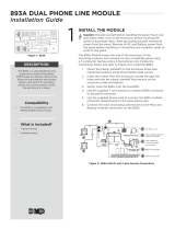
IMAGE REFERENCE SECTION
Handle
Bushing
Pin & Cable
Hook
Pawl
Spring
Pin
Snap Ring (3)
891:
891C:
891P:
892:
893:
893A:
894:
894Z-1:
895:
895A:
275-50:
895C:
896:
387:
16DS:
Latch
Spring
Snap Ring
Set Screw
Handle
Locknut
Drive Screw
893
891C
894Z-1
387
16DS
275-50
894
891
892
896
894Z-1
891P
893A
895A
895C
895
894Z-1
Model 890 Parts Available:
IMAGE #1
IMAGE #2

1-800-255-5387 • www.premier-mfg.com
premier manufacturing company
Page 5
(1) VERIFY THAT BOTH COUPLING’S AND
DRAWBAR EYE’S RATED CAPACITIES MEET
YOUR APPLICATION(S) REQUIREMENTS.
(2) DO NOT OVERLOAD COUPLING OR DRAWBAR
EYE.
(3) INSPECT COUPLING, LATCH AND DRAWBAR
EYE FOR CRACKS, BENDING DAMAGE OR
EXCESSIVE WEAR. DO NOT USE IF ANY OF
THESE CONDITIONS EXIST!
(4) CHECK FOR GAP BETWEEN CLOSED LATCH
AND TOP OF HORN OR COUPLING BALL.
DO NOT USE IF GAP IS 3/8 IN. OR MORE.
(5) MAKE SURE COUPLING IS LATCHED AND THAT
LATCH WILL NOT OPEN.
(6) PRIOR TO USE, ALWAYS CONNECT SAFETY
CHAINS OF ADEQUATE STRENGTH FOR
LOAD(S) BEING TOWED.
(7) DO NOT BIND-UP (JACKKNIFE) ANY
APPLICATION AS STRESSES CAN CAUSE
DAMAGE TO THE COUPLING, DRAWBAR EYE,
OTHER COMPONENTS OR ANY COMBINATION
OF THEM. JACKKNIFING MAY RESULT IN
FAILURE OF PRODUCTS OR COMPONENTS,
RESULTING IN DETACHMENT OF THE TRAILER
WHILE IN USE.
(8) DO NOT APPLY LUBRICANTS TO THE COUPLING
HOOK OR DRAWBAR EYE LOOP, AS THEY
CAN COVER UP POSSIBLE DAMAGE AND
ACCELERATE WEAR.
(9) ALWAYS ABIDE BY ALL APPLICABLE STATE AND
FEDERAL REGULATIONS GOVERNING SAFE
AND PROPER TRANSPORTATION.
(10) NEVER STRIKE ANY OF THESE COMPONENTS
WITH A HAMMER OR ANY OTHER DEVICE.
(11) ALWAYS VERIFY PROPER OPERATION
OF LATCHING SYSTEM AND COUPLING
COMPONENTS PRIOR TO DRIVE OFF.
(12) NEVER USE A COUPLING THAT YOU DO NOT
FULLY UNDERSTAND HOW TO PROPERLY
OPERATE AND VERIFY SECURE LATCHING OF.
(13) NEVER REPLACE ANY PART IN ANY OF
PREMIER’S ASSEMBLIES WITH NON-PREMIER
COMPONENTS. DOING SO WILL VOID ALL
WARRANTY AND POTENTIALLY COMPROMISE
THE UNIT’S INTEGRITY, WHICH COULD RESULT
IN PROPERTY DAMAGE, SERIOUS INJURY, OR
DEATH.
ATTENTION !
End Users must read and follow this information.
DISTRIBUTORS & OEM’S: Please ensure that your customers
are made aware of the following information on this page.

WARRANTY: We warrant all Premier products to be free from defects in material or workmanship for one year. We
will repair or replace, at our option, any Premier product which our examination reveals to be defective, provided that
the product is returned to our factory, at Tualatin, Oregon transportation prepaid, within one year of purchase
by the first retail purchaser. Our warranty does not extend to products which have been subject to misuse, neglect,
improper installation, maintenance or application, nor does our warranty extend to products which have been
repaired or altered outside of Premier’s facility unless the repair or alteration has been expressly authorized in
writing by Premier. This warranty is in lieu of all other warranties, express or implied, and excludes warranties
of merchantability, fitness for a particular purpose and otherwise, and in no event will Premier be liable for
incidental, special, contingent or consequential damages.
DISCLAIMER: Although great care has been taken to ensure accurate information throughout this document,
Premier Manufacturing Company must reserve the right to alter any information contained within. These changes
include but are not limited to: Dimensional changes, load capacity and availability of any part or assembly.
© 2009 Premier Manufacturing Company
All rights reserved. Any reproduction of the photographic images or any other portion of this document, including but not limited to the photocopying, or retention and/or storage
in a retrieval system of any kind, is strictly prohibited without prior express written permission from Premier Manufacturing Company.
PREMIER MANUFACTURING COMPANY
THE FIRST NAME IN QUALITY COUPLINGS
800-255-5387 (503) 234-9202
www.premier-mfg.com
1-800-255-5387 • www.premier-mfg.com
premier manufacturing company
Page 6
WARNING!
Important
Installation Instructions:
Do NOT attempt install
without rst reading all
attached instructions.
Installation must be
performed by a qualied
mechanic only.
890L & 890CL
Service Guidelines
Revised: 10/2009
/