OPERATING INSTRUCTIONS
FLOWSIC60
Continuous air flow measurement
for mining applications
Front page
Installation
Operation

2 FLOWSIC60 Operating Instructions 8014241/YTG9/V1-0/2016-02 © SICK Engineering GmbH
Document Information
Document ID
Title: Operating Instructions FLOWSIC60
Part No.: 8014241
Version: 1-0
Release: 2016-02
Described Product:
Product name: FLOWSIC60
Manufacturer
SICK Engineering GmbH
Bergener Ring 27 · D-01458 Ottendorf-Okrilla · Germany
Phone: +49 35 20552410
Fax: +49 35 20552450
E-mail: info.pa@sick.de
Trademarks
Windows is a Microsoft Corporation trademark.
Other product names used in this document may also be trade-
marks and are only used for identification purposes.
Original Documents
The English version 8014241 of this document is an original
document of SICK Engineering GmbH.
SICK Engineering GmbH assumes no liability for the correctness of
an unauthorized translation.
Please contact SICK Engineering GmbH or your local representa-
tive in case of doubt.
Legal Information
Subject to change without notice.
© SICK Engineering GmbH. All rights reserved.
Glossary
AC Alternating current
Al Aluminium
ATEX ATEX: Atmosphères Explosifs: Abbreviation for Euro-
pean standards that govern safety in potentially
explosive atmospheres
CSA Canadian Standards Association (www.csa.ca)
DC Direct Current
IEC International Electronical Commission
IECEx IEC system for certification in accordance with stan-
dards for devices for use in potentially explosive
atmospheres
IPxy Ingress Protection: Degree of protection of a device
in accordance with IEC/DIN EN 60529; x specifies
the protection against contact and impurities, y pro-
tection against moisture.
MDR Manufacturer Data Record
NAMUR Abbreviation for "Normen-Arbeitsgemeinschaft für
Mess- und Regeltechnik in der chemischen Indust-
rie", now "Interessengemeinschaft Automatisier-
ungstechnik der Prozessindustrie" (www.namur.de)

FLOWSIC60 Operating Instructions 8014241/YTG9/V1-0/2016-02 © SICK Engineering GmbH 3
Warning Symbols
Warning Levels / Signal Words
DANGER
Risk or hazardous situation which will result in severe personal
injury or death.
WARNING
Risk or hazardous situation which could result in severe personal
injury or death.
CAUTION
Hazard or unsafe practice which could result in personal injury or
property damage.
NOTICE
Hazard which could result in property damage.
Information Symbols
Hazard (general)
Hazard in potentially explosive atmospheres
Hazard by voltage
Information about the use in potentially explosive
atmospheres
Important technical information for this product
Important information on electric or electronic func-
tions
Supplementary information
Link to information at another place

Contents
4 FLOWSIC60 · Operating Instructions · 8014241/YTG9/V1-0/2016-02 · © SICK Engineering GmbH
1 Important Information . . . . . . . . . . . . . . . . . . . . . . . . . . . . . . . . . . . . . . . . . . . . . . . 7
1.1 About this document . . . . . . . . . . . . . . . . . . . . . . . . . . . . . . . . . . . . . . . . . . . . . . . . . . . . . . . . . 8
1.2 Main Hazards. . . . . . . . . . . . . . . . . . . . . . . . . . . . . . . . . . . . . . . . . . . . . . . . . . . . . . . . . . . . . . . . 8
1.3 Intended use . . . . . . . . . . . . . . . . . . . . . . . . . . . . . . . . . . . . . . . . . . . . . . . . . . . . . . . . . . . . . . . . 8
1.3.1 Product identification . . . . . . . . . . . . . . . . . . . . . . . . . . . . . . . . . . . . . . . . . . . . . . . . . . . . . . 8
1.3.2 Operation in potentially explosive atmospheres . . . . . . . . . . . . . . . . . . . . . . . . . . . . . . . 8
1.3.3 Restrictions of use . . . . . . . . . . . . . . . . . . . . . . . . . . . . . . . . . . . . . . . . . . . . . . . . . . . . . . . . . 9
1.4 Responsibility of user. . . . . . . . . . . . . . . . . . . . . . . . . . . . . . . . . . . . . . . . . . . . . . . . . . . . . . . . . 9
1.5 Safety instructions and protective measures. . . . . . . . . . . . . . . . . . . . . . . . . . . . . . . . . . . 10
2 Product description . . . . . . . . . . . . . . . . . . . . . . . . . . . . . . . . . . . . . . . . . . . . . . . . . . 13
2.1 System information . . . . . . . . . . . . . . . . . . . . . . . . . . . . . . . . . . . . . . . . . . . . . . . . . . . . . . . . . 14
2.1.1 System components . . . . . . . . . . . . . . . . . . . . . . . . . . . . . . . . . . . . . . . . . . . . . . . . . . . . . . 14
2.1.2 Determinig the gas velocity . . . . . . . . . . . . . . . . . . . . . . . . . . . . . . . . . . . . . . . . . . . . . . . . 15
2.1.3 Operating principle . . . . . . . . . . . . . . . . . . . . . . . . . . . . . . . . . . . . . . . . . . . . . . . . . . . . . . . 16
2.1.4 FLOWSIC60 Sensor . . . . . . . . . . . . . . . . . . . . . . . . . . . . . . . . . . . . . . . . . . . . . . . . . . . . . . . 17
2.1.5 Signal Processing unit (SPU) . . . . . . . . . . . . . . . . . . . . . . . . . . . . . . . . . . . . . . . . . . . . . . . 18
3 Installation. . . . . . . . . . . . . . . . . . . . . . . . . . . . . . . . . . . . . . . . . . . . . . . . . . . . . . . . . . . . 21
3.1 Mechanical installation . . . . . . . . . . . . . . . . . . . . . . . . . . . . . . . . . . . . . . . . . . . . . . . . . . . . . . 22
3.1.1 Project Planning . . . . . . . . . . . . . . . . . . . . . . . . . . . . . . . . . . . . . . . . . . . . . . . . . . . . . . . . . . 22
3.1.2 Mounting of sensors to tunnel wall . . . . . . . . . . . . . . . . . . . . . . . . . . . . . . . . . . . . . . . . . 25
3.1.3 Mounting of Signal processing Unit (SPU) and cable holder . . . . . . . . . . . . . . . . . . . 27
3.1.4 Alignment of sensors. . . . . . . . . . . . . . . . . . . . . . . . . . . . . . . . . . . . . . . . . . . . . . . . . . . . . . 27
3.1.5 Determination of path length and path angle . . . . . . . . . . . . . . . . . . . . . . . . . . . . . . . . 28
3.2 Electrical installation . . . . . . . . . . . . . . . . . . . . . . . . . . . . . . . . . . . . . . . . . . . . . . . . . . . . . . . . 29
3.2.1 General information. . . . . . . . . . . . . . . . . . . . . . . . . . . . . . . . . . . . . . . . . . . . . . . . . . . . . . . 30
3.2.2 Cable specifications for power supply and analog output . . . . . . . . . . . . . . . . . . . . . 31
3.2.3 Checking the cable loops . . . . . . . . . . . . . . . . . . . . . . . . . . . . . . . . . . . . . . . . . . . . . . . . . . 32
3.2.4 Electrical installation of Signal Processing Unit . . . . . . . . . . . . . . . . . . . . . . . . . . . . . . 33
3.2.5 Operation in hazardous areas . . . . . . . . . . . . . . . . . . . . . . . . . . . . . . . . . . . . . . . . . . . . . . 37
4 Commissioning and Operation. . . . . . . . . . . . . . . . . . . . . . . . . . . . . . . . . . . . 43
4.1 Operation and Menu structure of the SPU via LC-Display . . . . . . . . . . . . . . . . . . . . . . . . 44
4.2 Operational concept . . . . . . . . . . . . . . . . . . . . . . . . . . . . . . . . . . . . . . . . . . . . . . . . . . . . . . . . . 44
4.2.1 Menu structure on the LCD display . . . . . . . . . . . . . . . . . . . . . . . . . . . . . . . . . . . . . . . . . 45
4.2.2 Data editing in Configuration Mode . . . . . . . . . . . . . . . . . . . . . . . . . . . . . . . . . . . . . . . . . 49
4.3 Comissioning and initial start-up . . . . . . . . . . . . . . . . . . . . . . . . . . . . . . . . . . . . . . . . . . . . . . 50
4.4 Calibration / Zero-point adjustment . . . . . . . . . . . . . . . . . . . . . . . . . . . . . . . . . . . . . . . . . . . 50
4.5 Operating Modes, Meter States and Signal Output . . . . . . . . . . . . . . . . . . . . . . . . . . . . . 50
4.5.1 Operation Mode and Configuration Mode . . . . . . . . . . . . . . . . . . . . . . . . . . . . . . . . . . . 50
4.5.2 Meter States . . . . . . . . . . . . . . . . . . . . . . . . . . . . . . . . . . . . . . . . . . . . . . . . . . . . . . . . . . . . . 51
5 Maintenance . . . . . . . . . . . . . . . . . . . . . . . . . . . . . . . . . . . . . . . . . . . . . . . . . . . . . . . . . . 53
5.1 General notes . . . . . . . . . . . . . . . . . . . . . . . . . . . . . . . . . . . . . . . . . . . . . . . . . . . . . . . . . . . . . . 54
5.2 In case of works in tunnel . . . . . . . . . . . . . . . . . . . . . . . . . . . . . . . . . . . . . . . . . . . . . . . . . . . . 54
6Troubleshooting . . . . . . . . . . . . . . . . . . . . . . . . . . . . . . . . . . . . . . . . . . . . . . . . . . . . . . 55
6.1 General troubleshooting . . . . . . . . . . . . . . . . . . . . . . . . . . . . . . . . . . . . . . . . . . . . . . . . . . . . . 56
Contents

Contents
FLOWSIC60 · Operating Instructions · 8014241/YTG9/V1-0/2016-02 · © SICK Engineering GmbH 5
7 Annex. . . . . . . . . . . . . . . . . . . . . . . . . . . . . . . . . . . . . . . . . . . . . . . . . . . . . . . . . . . . . . . . . . . . 57
7.1 Technical data . . . . . . . . . . . . . . . . . . . . . . . . . . . . . . . . . . . . . . . . . . . . . . . . . . . . . . . . . . . . . . 58
7.2 Labelling . . . . . . . . . . . . . . . . . . . . . . . . . . . . . . . . . . . . . . . . . . . . . . . . . . . . . . . . . . . . . . . . . . . 59
7.3 Wiring diagram . . . . . . . . . . . . . . . . . . . . . . . . . . . . . . . . . . . . . . . . . . . . . . . . . . . . . . . . . . . . . . 60
7.4 Ex Certificate. . . . . . . . . . . . . . . . . . . . . . . . . . . . . . . . . . . . . . . . . . . . . . . . . . . . . . . . . . . . . . . . 61

Contents
6 FLOWSIC60 · Operating Instructions · 8014241/YTG9/V1-0/2016-02 · © SICK Engineering GmbH

Important Information
FLOWSIC60 · Operating Instructions · 8014241/YTG9/V1-0/2016-02 · © SICK Engineering GmbH 7
Subject to change without notice
FLOWSIC60
1 Important Information
About this document
Main hazards
Intended use
Responsibility of user
Safety instructions and protective measures

8 FLOWSIC60 · Operating Instructions · 8014241/YTG9/V1-0/2016-02 · © SICK Engineering GmbH
Important Information
Subject to change without notice
1.1 About this document
These Operating Instructions contain essential information on the function, installation,
start-up and maintenance of the FLOWSIC60 ultrasonic air velocity meter.
1.2 Main Hazards
Hazards due to explosive or combustible gases
The FLOWSIC60 measuring system may be used in potentially explosive atmospheres
according to the respective specifications.
1.3 Intended use
The FLOWSIC60 measuring system is designed for contactless measurement of air flow
velocity in explosive atmospheres.
1.3.1 Product identification
1.3.2 Operation in potentially explosive atmospheres
WARNING:Hazards due to explosive or combustible gases
In potentially explosive atmospheres, only use the FLOWSIC60 specified for
such use.
Observe the information contained in these Operating Instructions during
installation work on running equipment.
Product name: FLOWSIC60
Manufacturer:
SICK Engineering GmbH
Bergener Ring 27
01458 Ottendorf-Okrilla
Germany
WARNING: Explosion danger in hazardous areas!
The front cover of the device electronics is sealed. Do not open the front cover!
Otherwise the explosion protection of the device expires and serious damage
and injury can occur.
The FLOWSIC60 is approved for use in Ex Zone 0. The device designation for
use in hazardous areas is:
Electronics:
– Ex ia [ia] I Ma
– Ex ia [ia] IIC/IIB/IIA T4 Ga
Transducers:
–Ex ia I Ma
– Ex ia IIC/IIB/IIA T6/T4 Ga
Compliance with the above requirements is the sole responsibility of the user.

Important Information
FLOWSIC60 · Operating Instructions · 8014241/YTG9/V1-0/2016-02 · © SICK Engineering GmbH 9
Subject to change without notice
1.3.3 Restrictions of use
Refer to the type plate for the configuration of your FLOWSIC60.
Check the FLOWSIC60 is suitably equipped for your application (e.g., gas conditions).
1.4 Responsibility of user
Only put the FLOWSIC60 into operation after reading the Operating Instructions.
Observe all safety information.
If anything is not clear: Please contact the SICK Customer Service.
Designated users
The FLOWSIC60 measuring system may only be installed and operated by skilled
technicians who, based on their technical training and knowledge as well as knowledge of
the relevant regulations, can assess the tasks given and recognize the hazards involved.
Technicians must be skilled according to DIN VDE 0105 or IEC 364 or directly comparable
standards.
The named persons must have exact knowledge of operational hazards caused by
explosive gases as well as adequate knowledge of the measuring system gained through
training.
Correct use
Use the FLOWSIC60 only as described in these Operating Instructions. The manufac-
turer bears no responsibility for any other use.
Observe all measures necessary for conservation of value, e.g. for maintenance and
inspection and/or transport and storage.
Do not remove, add or modify any components on the device unless described and
specified in the official manufacturer information. Otherwise
– the device could become dangerous
– any warranty by the manufacturer becomes void
Do not use damaged components or parts.
Specific requirements for use of devices in hazardous areas
WARNING: Explosion hazard
Restrictions as documented in the Ex certification and this manual must be
observed. This includes observing limits for correct use as specified in the
Technical Data.
Cabling /installation, device set-up, maintenance and check may be only
carried out by experienced staff which has knowledge about the rules and
regulations for hazardous areas, in particular:
–type of protection
– installation rules
– area definition
Regulations to be applied:
– IEC 60079-14
– IEC 60079-17
or comparable national regulations.

10 FLOWSIC60 · Operating Instructions · 8014241/YTG9/V1-0/2016-02 · © SICK Engineering GmbH
Important Information
Subject to change without notice
Special local conditions
Observe the valid legal regulations as well as the technical rules deriving from imple-
mentation of these regulations applicable for the respective equipment during work
preparation and performance.
Special caution and attention is required on equipment with increased hazard potential
(explosion protection zones). Comply with existing special regulations.
Carry out work according to the local conditions specific for the equipment as well as
operational hazards and regulations.
Suitable protection devices and safety equipment for persons must be available accord-
ing to the respective hazard potential and be used by the personnel.
Retention of documents
Keep the Operating Instructions belonging to the measuring system as well as equipment
documentation onsite for reference at all times. Pass the respective documentation on to
any new owner of the measuring system.
Selection of materials
The user must check whether the intended materials of the device components are
suitable for the process conditions.
1.5 Safety instructions and protective measures
Using the equipment for any purpose other than intended, or improper operation may
result in injuries and damage to the equipment. Read this section and the notes and
warnings in the individual sections of this manual carefully and observe the instructions
given therein when carrying out any work on the FLOWSIC60 measuring system.
General instructions:
Always comply with the statutory provisions and the associated technical rules and reg-
ulations relevant to the equipment when preparing for and carrying out any work on the
measuring system. Always observe the relevant regulations.
Always consider local and equipment-specific conditions and process-specific dangers
when carrying out any work on the equipment.
Operating instructions and equipment documentation shall always be available on site.
Always observe the safety instructions and notes on the prevention of injuries and dam-
age given in these manuals.
Make sure appropriate protective accessories are available in sufficient supply. Always
use such protective accessories. Check that appropriate safety devices are fitted and
working correctly.
NOTICE:
If the FLOWSIC60 is used in conjunction with control equipment, the operator
must ensure that any failure or malfunction does not lead to damaging or
dangerous operating conditions.
In order to prevent device failure, the specified maintenance actions must be
carried out by qualified and experienced service staff at regular intervals.

Important Information
FLOWSIC60 · Operating Instructions · 8014241/YTG9/V1-0/2016-02 · © SICK Engineering GmbH 11
Subject to change without notice
Protection devices
Preventive measures for operating safety
NOTICE:
Suitable protection devices and safety equipment must be available according
to the respective hazard potential for use by personnel.
NOTICE:
The user must ensure that:
Neither failures nor erroneous measurements lead to operational states
that can cause damage or become dangerous
The specified maintenance and inspection tasks are carried out regularly
by qualified, experienced personnel.

12 FLOWSIC60 · Operating Instructions · 8014241/YTG9/V1-0/2016-02 · © SICK Engineering GmbH
Important Information
Subject to change without notice
Recognizing malfunctions
Every deviation from normal operation is to be regarded as a serious indication of a
functional impairment. These are, amongst others:
Warning displays (e.g. heavy contamination)
Large drifts in measured results
Increased power input
Higher temperatures of system parts
Monitoring device triggering
Smells or smoke emission
Avoiding damage
The operator must ensure the following to avoid malfunctions that can directly or indirectly
lead to injuries to persons or material damage:
The responsible maintenance personnel are present at any time and as quickly as pos-
sible
The maintenance personnel are adequately qualified to react correctly to malfunctions
of the measuring system and any resulting operational malfunctions (e.g. when used for
measurement and control purposes)
The malfunctioning equipment is switched off immediately in case of doubt and that
switching off does not cause collateral malfunctions.
Repairs
NOTICE:
Any repair work on FLOWSIC60 and its components will be carried out at the
manufacturer only.
In case of malfunction, the defective component can be exchanged and sent to
the manufacturer for repair.

Product description
FLOWSIC60 · Operating Instructions · 8014241/YTG9/V1-0/2016-02 · © SICK Engineering GmbH 13
Subject to change without notice
FLOWSIC60
2 Product description
System information

14 FLOWSIC60 · Operating Instructions · 8014241/YTG9/V1-0/2016-02 · © SICK Engineering GmbH
Product description
Subject to change without notice
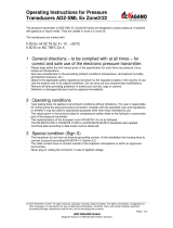
2.1 System information
The FLOWSIC60 transducers consist of two ultrasonic sensors, sensor cables and a signal
processing unit. The transducer is mounted in the holder. Coaxial connection cables are
used for the communication with the SPU.
2.1.1 System components
The FLOWSIC60 measuring system contains of the following components:
Sensor A and B
Signal processing unit (SPU) for control, evaluation and output of data
Connection cable, 2 pcs., for connections of transducers to junction box
Mounting set 2pcs., for fastening the wall brackets on the mine wall
Cable holder 1 pc., for storage of connection cables
Fig. 1 FLOWSIC60 measuring system
Sensor A
Sensor B
Signal Processing unit
Power
supply
Direction of
Air flow
Analog
output

Product description
FLOWSIC60 · Operating Instructions · 8014241/YTG9/V1-0/2016-02 · © SICK Engineering GmbH 15
Subject to change without notice
2.1.2 Determinig the gas velocity
Measuring path L is equal to the active measuring path, that is, the area through which the
gas flows. Given measuring path L, sound velocity c, and angle of inclination α between the
sound and flow direction, the sound transit time in the direction of the gas flow (forward
direction) when the signal is transmitted can be expressed as:
i.e. a relation in which, except for the two transit times measured, only the active
measuring path and the path angle exist as constants.
Valid against the flow is:
After the resolution to v:
v =
· ()
t
BA
=
t
AB
=
L 1 1
2 · cos α t
AB
t
BA
L
c - v · cos α
L
c + v · cos α
(2.1)
(2.3)
(2.2)

16 FLOWSIC60 · Operating Instructions · 8014241/YTG9/V1-0/2016-02 · © SICK Engineering GmbH
Product description
Subject to change without notice
2.1.3 Operating principle
FLOWSIC60 operates by measuring the transit time difference of ultrasonic pulses. The
sensors are mounted on both sides of the tunnel at a certain angle to the flow direction
(
Fig. 1).
The sensors alternately send ultrasonic pulses to each other. Depending on the installation
angle α and the air velocity v, the transit time of the respective sound direction varies as a
result of certain "acceleration and braking effects" (formulas 2.1 and 2.2). The transit time
difference of the sound pulses traveling from sensor A to B and in opposite direction is
directly related to the air velocity. The air velocity v is calculated from the transit time
difference of the ultrasonic pulses, independent of the velocity of sound. Changes in the
velocity of sound caused by pressure or temperature fluctuations, therefore, do not affect
the calculated air velocity with this method of measurement.

Product description
FLOWSIC60 · Operating Instructions · 8014241/YTG9/V1-0/2016-02 · © SICK Engineering GmbH 17
Subject to change without notice
2.1.4 FLOWSIC60 Sensor
Fig. 2 Sensor
Fig. 3 Dimensions - Sensor
Mounting
bracket
Sensor front
Safety screw

18 FLOWSIC60 · Operating Instructions · 8014241/YTG9/V1-0/2016-02 · © SICK Engineering GmbH
Product description
Subject to change without notice
2.1.5 Signal Processing unit (SPU)
Fig. 4 Signal processing unit
Signal Processing Unit (SPU)
Junction box
Cable holder
Cabling from transducer units

Product description
FLOWSIC60 · Operating Instructions · 8014241/YTG9/V1-0/2016-02 · © SICK Engineering GmbH 19
Subject to change without notice
Fig. 5 Dimensions - Signal processing unit

20 FLOWSIC60 · Operating Instructions · 8014241/YTG9/V1-0/2016-02 · © SICK Engineering GmbH
Product description
Subject to change without notice
Page is loading ...
Page is loading ...
Page is loading ...
Page is loading ...
Page is loading ...
Page is loading ...
Page is loading ...
Page is loading ...
Page is loading ...
Page is loading ...
Page is loading ...
Page is loading ...
Page is loading ...
Page is loading ...
Page is loading ...
Page is loading ...
Page is loading ...
Page is loading ...
Page is loading ...
Page is loading ...
Page is loading ...
Page is loading ...
Page is loading ...
Page is loading ...
Page is loading ...
Page is loading ...
Page is loading ...
Page is loading ...
Page is loading ...
Page is loading ...
Page is loading ...
Page is loading ...
Page is loading ...
Page is loading ...
Page is loading ...
Page is loading ...
Page is loading ...
Page is loading ...
Page is loading ...
Page is loading ...
Page is loading ...
Page is loading ...
Page is loading ...
Page is loading ...
Page is loading ...
Page is loading ...
Page is loading ...
Page is loading ...
Page is loading ...
Page is loading ...
Page is loading ...
/