SICK FLOWSIC600 DRU-S Operating instructions
- Category
- Measuring, testing & control
- Type
- Operating instructions

ADDENDUM TO OPERATING INSTRUCTIONS
Main
FLOWSIC600
Gas Flow Meter
FLOWSIC600 DRU-S
Gas flow meter
for upstream applications

2 FLOWSIC600 · Addendum to Operating Instructions · 8025324/18BQ/V2-1/2020-06 · © SICK Engineering GmbH
Document Information
Product
Product name: FLOWSIC600 DRU-S
Document ID
Title: Addendum to Operating Instructions
FLOWSIC600
Part No.: 8025324/18BQ
Version: 2-1
Release: 2020-06
Manufacturer
SICK Engineering GmbH
Bergener Ring 27 · D-01458 Ottendorf-Okrilla · Germany
Phone: +49 35205 52410
Fax: +49 35205 52450
E-mail: [email protected]
Trademarks
Windows is a Microsoft Corporation trademark.
Other product names used in this document may also be trade-
marks and are only used for identification purposes.
Original documents
The English version 8025324/18BQ of this document is an origi-
nal document from the manufacturer.
SICK Engineering GmbH assumes no liability for the correctness of
an unauthorized translation.
Please contact the publisher in case of doubt.
Legal information
Subject to change without notice.
© SICK Engineering GmbH. All rights reserved.
Glossary
Abbreviations used in this manual
DRU Differential Replacement Unit
CBM Condition Based Maintenance
CPA Canada Pipeline Accessories
LCD Liquid Crystal Display
OI Operating Instructions
LVF Liquid Volume Fraction
SPU Signal Processing Unit
TI Technical Information

FLOWSIC600 · Addendum to Operating Instructions · 8025324/18BQ/V2-1/2020-06 · © SICK Engineering GmbH 3
Warning Symbols
Warning levels / Signal words
HAZARD
Risk or hazardous situation which will result in severe personal
injury or death.
WARNING
Risk or hazardous situation which could result in severe personal
injury or death.
CAUTION
Hazard or unsafe practice which could result in personal injury or
property damage.
NOTICE
Hazard which could result in property damage.
Information Symbols
Warning
Important technical information for this product
Important information on electric or electronic func-
tions
Supplementary information

Contents
4 FLOWSIC600 · Addendum to Operating Instructions · 8025324/18BQ/V2-1/2020-06 · © SICK Engineering GmbH
1 Important Information . . . . . . . . . . . . . . . . . . . . . . . . . . . . . . . . . . . . . . . . . . . . . . . 5
1.1 About this document . . . . . . . . . . . . . . . . . . . . . . . . . . . . . . . . . . . . . . . . . . . . . . . . . . . . . . . . . 6
1.2 For your safety . . . . . . . . . . . . . . . . . . . . . . . . . . . . . . . . . . . . . . . . . . . . . . . . . . . . . . . . . . . . . . 6
2 FLOWSIC600 DRU-S . . . . . . . . . . . . . . . . . . . . . . . . . . . . . . . . . . . . . . . . . . . . . . . . . . 7
2.1 Product description . . . . . . . . . . . . . . . . . . . . . . . . . . . . . . . . . . . . . . . . . . . . . . . . . . . . . . . . . . 8
2.1.1 Overview . . . . . . . . . . . . . . . . . . . . . . . . . . . . . . . . . . . . . . . . . . . . . . . . . . . . . . . . . . . . . . . . . 8
2.2 Wet gas detection (option) . . . . . . . . . . . . . . . . . . . . . . . . . . . . . . . . . . . . . . . . . . . . . . . . . . . . 9
2.2.1 Activation of wet gas detection . . . . . . . . . . . . . . . . . . . . . . . . . . . . . . . . . . . . . . . . . . . . . 9
2.2.2 Signalization of wet gas detection . . . . . . . . . . . . . . . . . . . . . . . . . . . . . . . . . . . . . . . . . . . 9
2.3 Installation . . . . . . . . . . . . . . . . . . . . . . . . . . . . . . . . . . . . . . . . . . . . . . . . . . . . . . . . . . . . . . . . . 10
2.3.1 Mechanical Installation . . . . . . . . . . . . . . . . . . . . . . . . . . . . . . . . . . . . . . . . . . . . . . . . . . . 10
2.3.2 Electrical Installation . . . . . . . . . . . . . . . . . . . . . . . . . . . . . . . . . . . . . . . . . . . . . . . . . . . . . 10
2.4 Technical data . . . . . . . . . . . . . . . . . . . . . . . . . . . . . . . . . . . . . . . . . . . . . . . . . . . . . . . . . . . . . 11
2.5 Dimensional drawings . . . . . . . . . . . . . . . . . . . . . . . . . . . . . . . . . . . . . . . . . . . . . . . . . . . . . . . 12
Contents


6 FLOWSIC600 · Addendum to Operating Instructions · 8025324/18BQ/V2-1/2020-06 · © SICK Engineering GmbH
Important Information
1.1
About this document
This document is a supplement of the currently valid Operating Instructions FLOWSIC600
and may only be used in conjunction with them.
Special instructions for FLOWSIC600 DRU-S in this document overwrite related general
information in the FLOWSIC600 operating instructions.
1.2 For your safety
NOTICE:
Read the corresponding Operating Instructions carefully before using the
FLOWSIC600 DRU-S.
Special attention must be paid to all safety instructions and warnings for
assembly, installation and operation!


8 FLOWSIC600 · Addendum to Operating Instructions · 8025324/18BQ/V2-1/2020-06 · © SICK Engineering GmbH
FLOWSIC600 DRU-S
2.1
Product description
2.1.1 Overview
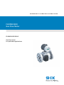
FLOWSIC600 DRU-S is an innovative ultrasonic dual-path gas flow meter for upstream
applications based on FLOWSIC600.
With its large measuring span FLOWSIC600 DRU-S covers a wide flow range that usually
requires several orifice plates. Due to its special design FLOWSIC600 DRU-S provides
reliable measurement performance, with high accuracy without need for a high-pressure
flow calibration.
High quality components with superior manufacturing precision and wet-gas robust
transducers ensure long-term measurement reliability even in challenging conditions.
FLOWSIC600 DRU-S provides advanced diagnostic capabilities for real-time monitoring of
the meter and the process. The ultrasonic measurement principle with direct path layout
makes FLOWSIC600 DRU-S virtually maintenance-free – even with high liquid loads.
For further information, please refer to OI FLOWSIC600 chapter 2.
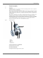
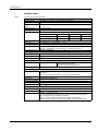
Figure 1 FLOWSIC600 DRU-S
Technical modifications to FLOWSIC600:
● Wet-gas robust meter design
● Sensors wet-gas robust
● Full bore meter section
● Diagnostic feature wet gas detection (option)
1 Flange
2 Meter body
3SPU
4 Pressure tap
5 Transducer cover
2
1
3
45

FLOWSIC600 DRU-S
FLOWSIC600 · Addendum to Operating Instructions · 8025324/18BQ/V2-1/2020-06 · © SICK Engineering GmbH 9
2.2
Wet gas detection (option)
FLOWSIC600 DRU-S maintains the diagnostic concept of FLOWSIC600 with self-monitoring
and User Warnings (refer to OI FLOWSIC600 chapter 2.3).
Additionally, the FLOWSIC600 DRU-S firmware is equipped with a diagnostic feature for
detection of wet gas inside the meter (wet gas detection, patent pending).
The wet gas detection uses real-time monitoring of multiple diagnostic parameters of the
FLOWSIC600 DRU-S in order to identify wet gas conditions (liquids in the gas stream such
as liquid hydrocarbons, water and oil). Liquids in the gas stream are usually undesired in
the gas production process and may require appropriate actions such as process
optimization or consideration for meter readings.
The wet gas detection typically detects wet gas with more than 0.5% of LVF in continuous
gas flow conditions.
2.2.1 Activation of wet gas detection
2.2.2 Signalization of wet gas detection
Table 1 Signalization of wet gas detection
Since the wet gas detection uses common standard diagnostic meter
parameters, the wet gas warning may be activated in parallel to other user-
warnings. In this case, a thorough analysis of the operating and process
conditions may be beneficial to find the root cause. Consult SICK for support.
The wet gas detection feature can be activated via Modbus command (please
refer to Short manual modbus FLOWSIC600).
LCD (SPU)
Warning 2008:
Wet gas
MODBUS Connection
#5069 (Bit 0x00000200UL) (refer to Short manual
modbus FLOWSIC600)
Meter logbook
Entry in Warning logbook [2] with time stamp “Wet gas
indication” (refer to OI FLOWSIC600 chapter 2.4.2).
If the wet gas detection generates a warning frequently, the activation
thresholds can be adjusted. Please contact SICK for support.
It is recommended to set the Warning logbook [2] to rolling in order to avoid
rapid filling of logbook in this case.

10 FLOWSIC600 · Addendum to Operating Instructions · 8025324/18BQ/V2-1/2020-06 · © SICK Engineering GmbH
FLOWSIC600 DRU-S
2.3
Installation
2.3.1 Mechanical Installation
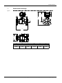
FLOWSIC600 DRU-S is only suitable for unidirectional use.
Make sure that the meter is mounted in the correct orientation (
Fig. 2).The flow direc-
tion is marked on the meter body.
For further instructions for mechanical installation please refer to OI FLOWSIC600,
chapter 3.3.
Figure 2 Installation scheme
2.3.2 Electrical Installation
The output configuration of FLOWSIC600 DRU-S can be taken from the instrument data-
sheet in the manufacturer data record (MDR) and from the wiring diagram inside the
rear housing cover.
For instructions on the electrical installation please refer to OI FLOWSIC600,
chapter 3.4.
For connection diagrams please refer to OI FLOWSIC600, chapter 7.4.
NOTICE:
Please note that the default installation instructions for FLOWSIC600 (OI
FLOWSIC600, §3.2.2) are not valid for FLOWSIC600 DRU-S.
≥ 3 DN
Straight inlet ≥20 DN
FLOWSIC600 DRU-S Straight outlet ≥ 5 DN
Pressure tap ½ " NPT female

FLOWSIC600 DRU-S
FLOWSIC600 · Addendum to Operating Instructions · 8025324/18BQ/V2-1/2020-06 · © SICK Engineering GmbH 11
2.4
Technical data
Table 2 Technical data FLOWSIC600 DRU-S
Meter characteristics and measuring parameters
Measured values Volume flow a.c., volume a. c., gas velocity, sound velocity
Measurement principle Ultrasonic transit time difference measurement
Number of measuring
paths
2
Nominal pipe size 2 inch Schedule 80
Measuring medium Natural gas
Measuring ranges
1,2,3
Volume flow a.c.
Q
min
Q
t
Q
max
Volume flow [ft³/h] 140 1,400 14,000
Volume flow [m³/h] 4 40 400
Repeatability
4
± 0.2 % of the measured value
Accuracy
3, 5
± 2 % from Q
t
to Q
max
(± 4 % from Q
min
to Q
t
)
Gas temperature -40 °F ... +212 °F (-40 °C ... +100 °C)
Operating pressure 70 psi (g) … 1480 psi (g) at 100 °F (5 bar (g) … 102.0 bar (g) at 38 °C)
70 psi (g) … 1350 psi (g) at 212 °F (5 bar (g) … 93.2 bar (g) at 100 °C)
Flange connection ANSI B16.5, Cl.600 RF
Ambient conditions
Ambient temperature -40 °F ... +140 °F (-40 °C ... +60 °C)
Storage temperature -40 °F ... +158 °F (-40 °C ... +70 °C)
Ambient humidity ≤ 95 % Relative humidity
Approvals
Ex approvals NEC/CEC Class I, Division 1, Group D T4
Class I, Division 2, Group D T4
Ultrasonic transducers intrinsically safe
Enclosure rating IP66/IP67
Outputs and interfaces
Digital outputs 2 DO and 1 FO:
30 V, 10 mA
Passive, galvanically isolated, Open Collector, fmax = 6 kHz (scalable)
Interfaces RS-485 (2x, for configuration data output and diagnosis)
Bus protocol MODBUS ASCII, MODBUS RTU
Dimensions and Weight
Dimensions (W x H x D) See dimensional drawings
Weight 77 lbs (35 kg)
Electrical connection
Voltage 12 ... 28.8 V DC
Power consumption ≤ 1 W
1
Below Q
min
reduced accuracy
2
Q
max
can be limited by the working pressure and attenuation of the gas medium.
3
Under consideration of installation requirements
4
From Q
t
to Q
max
and under consideration of installation requirements
5
Verified with pipe configurations according to OIML R-137:2012 Annex B (mild)

12 FLOWSIC600 · Addendum to Operating Instructions · 8025324/18BQ/V2-1/2020-06 · © SICK Engineering GmbH
FLOWSIC600 DRU-S
2.5
Dimensional drawings
Figure 3 FLOWSIC600 DRU-S
A B C D E F
mm (in).
250
(9.54)
49.3
(1.94)
252
(9.94)
335
(13.20)
165.1
(6.50)
228
(8.99)
A
B
C
D
E
F

FLOWSIC600 DRU-S
FLOWSIC600 · Addendum to Operating Instructions · 8025324/18BQ/V2-1/2020-06 · © SICK Engineering GmbH 13

SICK AG | Waldkirch | Germany | www.sick.com
'HWDLOHGDGGUHVVHVDQGIXUWKHUORFDWLRQVDWwww.sick.com
Australia
3KRQH
²WROOIUHH
(0DLO VDOHV#VLFNFRPDX
Austria
3KRQH
(0DLORIILFH#VLFNDW
Belgium/Luxembourg
3KRQH
(0DLOLQIR#VLFNEH
Brazil
3KRQH
(0DLOFRPHUFLDO#VLFNFRPEU
Canada
3KRQH
E-Mail [email protected]
Czech Republic
3KRQH
E-Mail [email protected]
Chile
3KRQH
E-Mail [email protected]
China
3KRQH
(0DLO LQIRFKLQD#VLFNQHWFQ
Denmark
3KRQH
E-Mail [email protected]
Finland
3KRQH
(0DLOVLFN#VLFNIL
France
3KRQH
(0DLOLQIR#VLFNIU
Germany
3KRQH
(0DLOLQIR#VLFNGH
Greece
3KRQH
(0DLO RIILFH#VLFNFRPJU
Hong Kong
3KRQH
(0DLO JKN#VLFNFRPKN
Hungary
3KRQH
(0DLOHUWHNHVLWHV#VLFNKX
India
3KRQH
(0DLOLQIR#VLFNLQGLDFRP
Israel
3KRQH
(0DLOLQIR#VLFNVHQVRUVFRP
Italy
3KRQH
(0DLOLQIR#VLFNLW
Japan
3KRQH
(0DLOVXSSRUW#VLFNMS
Malaysia
3KRQH
(0DLOHQTXLU\P\#VLFNFRP
Mexico
3KRQH
E-Mail me[email protected]
Netherlands
3KRQH
(0DLOLQIR#VLFNQO
New Zealand
3KRQH
²WROOIUHH
E-Mail [email protected]z
Norway
3KRQH
E-Mail [email protected]
Poland
3KRQH
(0DLOLQIR#VLFNSO
Romania
3KRQH
(0DLO RIILFH#VLFNUR
Russia
3KRQH
(0DLOLQIR#VLFNUX
Singapore
3KRQH
(0DLOVDOHVJVJ#VLFNFRP
Slovakia
3KRQH
E-Mail [email protected]
Slovenia
3KRQH
(0DLORIILFH#VLFNVL
South Africa
3KRQH
(0DLOLQIR#VLFNDXWRPDWLRQFR]D
South Korea
3KRQH
(0DLOLQIRNRUHD#VLFNFRP
Spain
3KRQH
(0DLOLQIR#VLFNHV
Sweden
3KRQH
(0DLOLQIR#VLFNVH
Switzerland
3KRQH
(0DLOFRQWDFW#VLFNFK
Taiwan
3KRQH
(0DLOVDOHV#VLFNFRPWZ
Thailand
3KRQH
(0DLOPDUFRPWK#VLFNFRP
Turkey
3KRQH
(0DLOLQIR#VLFNFRPWU
United Arab Emirates
3KRQH
(0DLOFRQWDFW#VLFNDH
United Kingdom
3KRQH
(0DLOLQIR#VLFNFRXN
USA
3KRQH
(0DLOLQIR#VLFNFRP
Vietnam
3KRQH
(0DLOVDOHVJVJ#VLFNFRP
8025324/18BQ/2-1/2020-06
-
 1
1
-
 2
2
-
 3
3
-
 4
4
-
 5
5
-
 6
6
-
 7
7
-
 8
8
-
 9
9
-
 10
10
-
 11
11
-
 12
12
-
 13
13
-
 14
14


SICK FLOWSIC600 DRU-S Operating instructions
- Category
- Measuring, testing & control
- Type
- Operating instructions
Ask a question and I''ll find the answer in the document
Finding information in a document is now easier with AI
Related papers
-
SICK FLOWSIC600 Ultrasonic Gas Flow Meter Operating instructions
-
-
-
-
-
-
-
-
-
Other documents
-
Broan PPH3RF Installation guide
-
KROHNE OPTISONIC 7060 User manual
-
ADC Digivance ICS 1900 Installation Instructions Manual
-
 ADZ Nagano ADZ-SML Ex Zone2/22 Operating instructions
-
Elster UFM Series 6 Operating instructions
-
Munters RWM 1.5 Owner's manual
-
Furuno VR7000 User manual
-
-
-
