Page is loading ...

CLEAN BURN MODELS: CB-1750, CB-2500, and CB-3250
MULTI-OIL FURNACES
with CB-525-S2 BURNER
PUBLICATION DATE: 07/16/13, Rev. 13 CLEAN BURN PART # 43195
IMPORTANT FOR U.S. INSTALLATIONS: All installations must be made in accordance with state and local codes
which may differ from the information provided in this manual. Save these instructions for reference.
IMPORTANT FOR CANADIAN INSTALLATIONS: These instructions have been reviewed and accepted by
Underwriters' Laboratories of Canada as being appropriate for the installation of the ULC labelled products
identied herein. The use of these instructions for the installation of products NOT bearing the ULC label and
NOT identied herein may result in an unacceptable or hazardous installation.
IMPORTANT FOR CANADIAN INSTALLATIONS: The installation of this equipment is to be accomplished by
qualied personnel and in accordance with the regulation of authorities having jurisdiction and CSA Standard B 139,
Installation Code for Oil Burning Equipment.
WARNING: DO NOT assemble, install, operate, or maintain this equipment without rst
reading and understanding the information provided in this manual. Installation and
service must be accomplished by qualied personnel. Failure to follow all safety precautions
and procedures as stated in this manual may result in property damage, serious personal injury
or death.
OPERATOR'S MANUAL
IN THE VICINITY OF THIS OR ANY APPLIANCE !!
OR OTHER FLAMMABLE VAPORS AND LIQUIDS
DO NOT STORE GASOLINE
FOR YOUR SAFETY -
ENERGY SYSTEMS
www.cleanburn.com
I88435-D
USED-OIL BURNING
APPLIANCE
USED OIL-FIRED
FURNACE
LISTED
#MH15393 (N)


Clean Burn, LLC, MANUFACTURER, hereby warrants that MANUFACTURER’s products shall be free from defect in
material and workmanship under normal use according to the provisions and limitations herein set forth.
MANUFACTURER warrants the heat exchanger/combustion chamber for a period of ten (10) years or 15,000 hours,
whichever comes rst), from the date of purchase by the original purchaser, as follows:
If the defect occurs within the rst ten (10 years or 15,000 hours, whichever comes rst), Clean Burn will replace or repair
the heat exchanger/combustion chamber.
MANUFACTURER warrants all other Clean Burn component parts, including the energy retention disk, for a period of
one (1) year from the date of purchase by the original purchaser.
LIMITATIONS:
The obligation of MANUFACTURER for breach of warranty shall be limited to products manufactured by
MANUFACTURER, (1) that are installed, operated and maintained according to MANUFACTURER’s instructions furnished
and/or available to the purchaser upon request; (2) that are installed according to all other applicable Federal, State and local
codes or regulations; and (3) that the purchaser substantiates were defective in material and workmanship notwithstanding
that they were properly installed and correctly maintained as set forth above and were not abused or misused. The
MANUFACTURER may request service records or require photos of the installation or defect.
The obligation of MANUFACTURER shall be limited to replacing or repairing the defective product, at the option of the
MANUFACTURER. MANUFACTURER shall not be responsible for any labor or costs or removal or reinstallation of its
products and shall not be liable for transportation costs to and from its plant at Janesville, Wisconsin.
Use of parts for modication or repair of the product or any component part thereof not authorized or manufactured by
MANUFACTURER specically for such product shall void this warranty.
This warranty shall not apply to any damage to or defect in any of MANUFACTURER’s products that is directly or indirectly
caused by (1) force majeure, Act of God or other accident not related to an inherent product defect; or (2) abuse, misuse or
neglect of such product, including any damage caused by improper assembly, installation, adjustment, service, maintenance
or faulty instruction of the purchaser.
Other than as expressly set forth hereinabove, MANUFACTURER makes no other warranty, express or implied, with
respect to any of MANUFACTURER’s products, including but not limited to any warranty of merchantability or tness for a
particular purpose.
And in no event shall MANUFACTURER be responsible for any incidental or consequential damages of any nature suffered
by purchaser or any other person or entity caused in whole or in part by any defect in any of MANUFACTURER’s products.
Any person or entity to whom this warranty extends and who claims breach of warranty against MANUFACTURER must
bring suit thereon within one year from the date of occurrence of such breach of warranty or be forever barred from any and
all legal or other remedies for such breach of warranty.
MANUFACTURER is not responsible for and hereby disclaims any undertaking, representation or warranty made by any
dealer, distributor or other person that is inconsistent with or in any way more expansive than the provisions of this limited
warranty.
WARRANTY INFORMATION
WASTE OIL FURNACE
CLEAN BURN

This warranty grants specic legal rights and shall be read in conformity with applicable state law. In some jurisdictions,
the applicable law mandates warranty provisions that provide greater legal rights than those provided for herein. In such
case, this limited warranty shall be read to include such mandated provisions; and any provision herein that is prohibited
or unenforceable in any such jurisdiction shall, as to such jurisdiction, be ineffective to the extent of such prohibition or
unenforceability without invalidating the remaining provisions and without affecting the validity or enforceability of such
provision in any other jurisdiction(s).
TRADEMARKS
The Clean Burn logo is a trademark of Clean Burn, LLC. All other brand or product names mentioned are the registered
trademarks or trademarks of their respective owners.
COPYRIGHT
Copyright © 2013 Clean Burn, LLC. All rights reserved. No part of this publication may be reproduced, or distributed
without the prior written permission of Clean Burn, LLC. 4109 Capital Circle, Janesville, WI 53546. Subject to change
without notice.
Warranty (continued)

TABLE OF CONTENTS
SECTION 1: INTRODUCTION ............................................................................................................ 1-1
Guide to this Manual ..................................................................................................................... 1-1
For Your Safety... ........................................................................................................................... 1-2
Guidelines for Furnace Usage ................................................................................................ 1-4
Guidelines for Used Oil Tanks ............................................................................................... 1-5
Safety Labels .......................................................................................................................... 1-6
SECTION 2: UNPACKING ................................................................................................................... 2-1
Removing the Shipping Crate ....................................................................................................... 2-1
Unpacking and Inspecting All Components .................................................................................. 2-1
Furnace Component List ....................................................................................................... 2-1
Unpacking Items Packed Inside the Furnace 2-2
Warranty Registration .................................................................................................................... 2-2
SECTION 3: FURNACE ASSEMBLY ................................................................................................ 3-1
Understanding Assembly ............................................................................................................... 3-1
Required Tools and Materials ................................................................................................ 3-1
Installing the CB-1750 and CB-2500 Blower Assembly .............................................................. 3-3
Wiring the CB-1750 and CB-2500 Blower Motor ................................................................ 3-4
Installing the CB-3250 Blower Assembly ..................................................................................... 3-6
Mounting the CB-3250 Blower .............................................................................................. 3-6
Installing the CB-3250 Blower Motor on the Blower ............................................................ 3-6
Wiring the CB-3250 Blower Motor ...................................................................................... 3-6
Installing the Motor Pulley, Blower Pulley, and V-Belt ......................................................... 3-8
Installing the Belt Guard and Blower Guard ....................................................................... 3-10
Determining the Air Discharge Conguration ............................................................................ 3-10
Installing the Hot Air Discharge Components ............................................................................. 3-12
Installing the Energy Retention Disc ........................................................................................... 3-14
Installing the Energy Retention Disc on the Combustion Chamber .................................... 3-14
Closing the Furnace Door .................................................................................................... 3-14
Installing the Burner .................................................................................................................... 3-15
Checking the Burner Nozzle and Electrodes ....................................................................... 3-15
Mounting the Burner on the Hinge Bracket ......................................................................... 3-16
Installing the Connector Block, Oil Line Tubing, and Air Line Tubing...................................... 3-17
Installing the Connector Block on the Furnace Door .......................................................... 3-17
Installing the Oil Line Tubing .............................................................................................. 3-17
Installing the Air Line Tubing .............................................................................................. 3-18
Locking the Burner into Firing Position .............................................................................. 3-19
SECTION 4: FURNACE INSTALLATION ......................................................................................... 4-1
Understanding Installation............................................................................................................. 4-1
Selecting a Location ...................................................................................................................... 4-3
Guidelines for Selecting a Location ....................................................................................... 4-3
Mounting the Furnace.................................................................................................................... 4-4
Ceiling Mounting ................................................................................................................... 4-4
Raised Platform Mounting ..................................................................................................... 4-5
Floor Mounting ...................................................................................................................... 4-5
Oil Tank Installation Specications ............................................................................................... 4-7
Installing the Tank Vent and Emergency Vent ....................................................................... 4-8
Installing the Metering Pump ........................................................................................................ 4-9

TABLE OF CONTENTS
Preparing for Installation ....................................................................................................... 4-9
Standard Mounting: Vertical Positioning ............................................................................... 4-9
SECTION 4: FURNACE INSTALLATION (continued) .........................................................................
Alternate Mounting: Horizontal Positioning ................................................................................4-11
Wiring the Furnace and Pump ..................................................................................................... 4-12
Wiring to the Furnace ........................................................................................................... 4-12
Wiring to the Metering Pump............................................................................................... 4-12
Installing the Suction Oil Line Components ............................................................................... 4-13
Installing the Pressure Relief Oil Line Back to the Tank ............................................................ 4-16
Installing the Pressure Oil Line Components .............................................................................. 4-17
Installing the Compressed Air Line ............................................................................................. 4-17
Installing the Stack ...................................................................................................................... 4-18
Stack Design and Specications .......................................................................................... 4-18
Installing the Interior Stack .................................................................................................. 4-21
Installing the Barometric Damper ........................................................................................ 4-21
Installing the Stack Safety Switch For Canadian Installations ............................................ 4-22
Resetting the Stack Safety Switch ................................................................................. 4-23
Understanding the Stack Safety Switch ......................................................................... 4-23
Installing the Stack Penetration ............................................................................................ 4-24
Installing the Exterior Stack ................................................................................................. 4-24
Installing the Stack Cap ....................................................................................................... 4-24
Installing the Optional Draft Inducer ................................................................................... 4-24
Installing the Wall Thermostat ..................................................................................................... 4-26
Replacing the Wall Thermostat Batteries ............................................................................. 4-26
Inspecting the Furnace Installation .............................................................................................. 4-26
SECTION 5: METERING PUMP PRIMING .............................................................................. 5-1
Understanding Metering Pump Priming ........................................................................................ 5-1
Required Tools and Materials ................................................................................................ 5-1
Priming the Metering Pump .......................................................................................................... 5-2
Vacuum Testing the Oil Pump ....................................................................................................... 5-4
SECTION 6: STARTING AND ADJUSTING THE BURNER ................................................... 6-1
Understanding Burner Startup and Adjustment 6-1
Preparing the Burner for Startup ................................................................................................... 6-1
Starting the Burner ........................................................................................................................ 6-3
Checking the Operation of the Blower Motor ............................................................................. 6-4
SECTION 7: RESETTING THE FURNACE AND BURNER .................................................... 7-1
Understanding Furnace/Burner Shutdowns ................................................................................... 7-1
The Oil Primary Control ................................................................................................................ 7-1
Resetting the Oil Primary Control ......................................................................................... 7-1
The Blower Switch ........................................................................................................................ 7-2
The Hi-Temp Limit Switches ........................................................................................................ 7-2
Understanding the L-200 Hi-Temp Limit Switch .................................................................. 7-2
Understanding the L-290 Auxiliary Auto Reset Hi-Temp Limit Switch ............................... 7-2
SECTION 8: ADJUSTING THE DRAFT OVER FIRE .............................................................. 8-1
Checking for Correct Draft Over Fire ........................................................................................... 8-1
Adjusting the Barometric Damper................................................................................................. 8-2

TABLE OF CONTENTS
SECTION 8: FURNACE INSTALLATION (continued) .........................................................................
Solving Draft Overre Problems ........................................................................................... 8-2
Understanding the Effect of Exhaust Fans on Draft .............................................................. 8-3
Checking Draft Overre to Determine Severity of Backdraft ............................................... 8-3
Installing a Make-up Air Louver ............................................................................................ 8-5
SECTION 9: MAINTENANCE .................................................................................................. 9-1
Understanding Maintenance .......................................................................................................... 9-1
Periodic Burner Inspection ............................................................................................................ 9-2
Cleaning the Canister Filter ........................................................................................................... 9-3
Servicing the Metering Pump ........................................................................................................ 9-4
Cleaning the Check Valve ............................................................................................................. 9-5
Cleaning the Tank .......................................................................................................................... 9-6
Cleaning Ash from the Furnace ..................................................................................................... 9-7
Annual Burner Tune-up ................................................................................................................. 9-9
End of Season Maintenance .......................................................................................................... 9-9
Cleaning and Maintaining the Optional draft Inducer ................................................................... 9-9
SECTION 10: TROUBLESHOOTING .................................................................................... 10-1
Flow Chart ................................................................................................................................... 10-2
Troubleshooting Tables ............................................................................................................... 10-3
APPENDIX A
Furnace Technical Specications ................................................................................................. A-1
Burner Technical Specications ................................................................................................... A-2
Furnace Dimensions .................................................................................................................... A-2
Burner Components ...................................................................................................................... A-4
Removing the Nozzle for cleaning ........................................................................................ A-9
CB-1750 Furnace Components .................................................................................................. A-10
CB-1750 Blower Components ................................................................................................... A-12
CB-2500 Furnace Components .................................................................................................. A-14
CB-2500 Blower Components ................................................................................................... A-16
CB-3250 Furnace Components .................................................................................................. A-18
CB-3250 Blower Components ................................................................................................... A-20
Metering Pump Components ...................................................................................................... A-22
APPENDIX B
Wiring Diagrams ...........................................................................................................................B-1
CB-1750 Furnace Wiring Diagram ........................................................................................B-1
CB-2500 Furnace Wiring Diagram ........................................................................................B-2
CB-3250 Furnace Wiring Diagram (115 Volts) .....................................................................B-3
CB-3250 Furnace Wiring Diagram (230 Volts) .....................................................................B-4
Burner Wiring Diagram..........................................................................................................B-5
CB-1750 Ladder Schematic ...................................................................................................B-6
CB-2500 Ladder Schematic ...................................................................................................B-7
CB-3250 Ladder Schematic (115 Volts) ................................................................................B-8
CB-3250 Ladder Schematic (230 Volts) ................................................................................B-9
Metering Pump Wiring Schematic .......................................................................................B-10
CAD Cell Oil Primary Control Data Sheets ........................................................................B-11

TABLE OF CONTENTS
APPENDIX C
Furnace Service Record ................................................................................................................. C-1

Operator's Manual: Models CB-1750, CB-2500 & CB-3250
1-1
SECTION 1: INTRODUCTION
Guide to this Manual
This manual contains all the information necessary to safely install and operate the Clean Burn Furnace
Models CB-1750, CB-2500 and CB-3250. Consult the Table of Contents for a detailed list of topics
covered. You'll nd this manual's step-by-step procedures easy to follow and understand. Should ques-
tions arise, please contact your Clean Burn dealer before starting any of the procedures in this manual.
As you follow the directions in this manual, you'll discover that assembling and operating your new
furnace involves ve basic activities as outlined here:
• UNPACKING ..................................................................................................... (Section 2)
• ASSEMBLY ........................................................................................................ (Section 3)
• INSTALLATION .............................................................................................. (Section 4)
• OPERATION
• Metering Pump Priming ........................................................................ (Section 5)
• Starting and Adjusting the Burner ....................................................... (Section 6)
• Resetting the Furnace and Burner ....................................................... (Section 7)
• Adjusting the Draft ............................................................................... (Section 8)
• MAINTENANCE .............................................................................................. (Section 9)
The manual also contains important and detailed technical
reference materials which are located at the back of the
manual in the Appendixes.
Please read all sections carefully--including the important
safety information found in this section--before beginning
any installation/operation procedures; doing so ensures
your safety and the optimal performance of your Clean
Burn furnace.
WARNING!
STOP
YOUR SAFETY IS AT STAKE!
DO NOT INSTALL, OPERATE OR
MAINTAIN THIS EQUIPMENT
WITHOUT FIRST READING
AND UNDERSTANDING THE
OPERATOR'S MANUAL!

Operator's Manual: Models CB-1750, CB-2500 & CB-3250
1-2
For Your Safety...
For your safety, Clean Burn documentation contains the following types of safety statements (listed here
in order of increasing intensity):
• NOTE: A clarication of previous information or additional pertinent information.
• ATTENTION: A safety statement indicating that potential equipment damage may occur if
instructions are not followed.
CAUTION: A safety statement that reminds of safety practices or directs attention to unsafe
practices which could result in personal injury if proper precautions are not taken.
WARNING: A strong safetystatement indicating that a hazard exists which can result in
injury or death if proper precautions are not taken.
DANGER! The utmost levels of safety must be observed; an extreme hazard exists which
would result in high probability of death or irreparable serious personal injury if proper
precautions are not taken.
In addition to observing the specic precautions listed throughout the manual, the following general
precautions apply and must be heeded to ensure proper, safe furnace operation.
DANGER! DO NOT create a re or explosion hazard by storing or using gasoline or other
ammable or explosive liquids or vapors near your furnace.
DANGER! DO NOT operate your furnace if excess oil, oil vapor or fumes have
accumulated in or near your furnace. As with any oil burning furnace, improper installation,
operation or maintenance may result in a re or explosion hazard.
WARNING: DO NOT add inappropriate or hazardous materials to your used oil, such as:
• Anti-freeze
• Carburetor cleaner
• Paint thinner
• Parts washer solvents
• Gasoline
• Oil additives
• Any other inappropriate/hazardous
material
WARNING: Burning chlorinated materials (chlorinated solvents and oils) is illegal, will
severely damage your heat exchanger, immediately void your warranty, and adversely affect
the proper, safe operation of your furnace. Instruct your personnel to never add hazardous
materials to your used oil.

Operator's Manual: Models CB-1750, CB-2500 & CB-3250
1-3
WARNING: Never alter or modify your furnace without prior written consent of
Clean Burn, LLC. Unauthorized modications or alteration can adversely affect the proper,
safe operation of your furnace.
WARNING: The burner which is shipped with your Clean Burn furnace is to be used only
with your furnace according to the instructions provided in this manual. DO NOT use the
burner for any other purpose!
WARNING: The Best Operator is a Careful Operator! By using common sense,
observing general safety rules, and adhering to the precautions specic to the equipment,
you, the operator, can promote safe equipment operation. Failure to use common sense,
observegeneralsafetyrules,andadheretotheprecautionsspecictotheequipmentmay
resultinequipmentdamage,re,explosion,personalinjuryand/ordeath.
WARNING: The installation, operation, and maintenance of this equipment in the U.S.
must be accomplished by qualied personnel and in compliance with the specications in the
Clean Burn Operator's Manual and with all national, state, and local codes or authorities
having jurisdiction over environmental control, building inspection and fuel, re and
electrical safety and the following standards:
NFPA 30 Flammable and Combustible Liquids Code
NFPA 30A Automotive and Marine Service Station Code
NFPA 31 Standard for the Installation of Oil Burning Equipment
NFPA 211 Chimneys, Fireplaces, Vents and Solid Fuel Burning Appliances
NFPA 88A Parking Structures
NFPA 88B Repair Garages
NFPA 70 National Electrical Code
The International Mechanical Code
The International Building Code
The International Fire Code
The International Fuel Gas Code
Likewise, the installation, operation, and maintenance of this equipment in Canada is to be
accomplished by qualied personnel and in compliance with the specications in the
Clean Burn Operator's Manual and in accordance with the regulation of authorities having
jurisdiction and the following CSA Standards: B139 - Installation Code for Oil Burning
Equipment; B140.0 - General Requirements for Oil Burning Equipment; and C22.1 -
Canadian Electrical Code, Part 1.
Failuretocomplywiththesestandardsandrequirementsmayresultinequipment
damage,re,explosion,personalinjuryand/ordeath.
For Your Safety... (continued)

Operator's Manual: Models CB-1750, CB-2500 & CB-3250
1-4
Guidelines for Furnace Usage
• This furnace is listed for commercial and/or industrial use only; it is not listed for residential
use.
• This furnace is listed with Underwriters Laboratory (UL) and Underwriters' Laboratories of
Canada (ULC) to burn the following fuels:
• Used crankcase oil up to 50 SAE
• Used transmission uid (for U.S.)
• Used hydraulic oils
• #2 fuel oil
• #4 fuel oil
• #5 fuel oil
NOTE: Used oils may contain other substances, including gasoline, that may hinder
performance.
• Make sure you comply with all EPA regulations concerning the use of your furnace. EPA
regulations require that:
• Your used oil is generated on-site. You may also accept used oil from
"do-it-yourself" oil changers.
• Hazardous wastes, such as chlorinated solvents, are NOT to be mixed with your
used oil.
• The ue gases are vented to the outdoors with an appropriate stack.
• Your used oil is recycled as fuel for "heat recovery". DO NOT operate your furnace
in warm weather just to burn oil.
Contact your Clean Burn dealer for current EPA regulations.
• If your furnace ever requires service, call your Clean Burn dealer. DO NOT allow
untrained, unauthorized personnel to service your furnace. Make sure that your furnace
receives annual preventative maintenance to ensure optimal performance.
For Your Safety... (continued)

Operator's Manual: Models CB-1750, CB-2500 & CB-3250
1-5
For Your Safety... (continued)
Guidelines for Used Oil Tanks
For the safe storage of used oil and the safety of
persons in the vicinity of the used oil supply tank,
ensure that your tank installation adheres to the
following safety guidelines:
• The tank installation must meet all
national and local codes. Consult your
local municipal authorities for more
information as necessary.
• Review and adhere to the safety
guidelines for used oil supply tanks
as stated in the WARNING shown.
• Ensure that the tank for your furnace
installation complies with all code and
safety requirements as stated here. If the
tank does not comply, DO NOT use it.
• If you do not have a copy of the tank
safety label pictured at right, please
contact your Clean Burn dealer for the
label, which is to be afxed directly on
your used oil supply tank.
Follow all instructions
for tank installation in
Operator's Manual.
ONLY place these listed substances in
this used-oil supply tank:
• Used crankcase oil
• Used automatic transmission uid
• Used hydraulic oil
• #2 fuel oil
Do NOT place ammable or corrosive
substances such as gasoline, chlorinated
oils, solvents, paint thinners, or any other
unsafe substances in this used-oil supply tank.
Do NOT weld or allow open ame within
35 feet of this used-oil supply tank.
Tank installation MUST comply with NFPA
30 and 31 Fire Codes, including the following
requirements:
• Tank must be listed to UL 80 or UL 142.
• Tank must be vented to outside.
• Emergency vent or explosion relief must
be installed on tank.
• Inside ll allowed only with funnel including 1/4
turn-to-close fall valve, which must be
closed after lling.
• All other openings must be plugged
• All oil lines must be constructed of copper,
steel, or brass components. Do NOT use
rubber or plastic tubing or piping, or any other
inappropriate material.
42366 Rev. 2
Fire and explosion hazards
To prevent serious injury or death:
WARNING

Operator's Manual: Models CB-1750, CB-2500 & CB-3250
1-6
For Your Safety... (continued)
Safety Labels
Following are the locations and descriptions of all labels on your furnace cabinet. The following
illustrations show the location of ALL labels on your furnace. Please note that some labels denote model
number, model description, etc. while others contain important safety messages.
Each Safety Label contains an important safety message starting with a key word as discussed earlier
in this section (e.g. ATTENTION, CAUTION, WARNING, DANGER). For your safety and the safe
operation of your furnace, review all labels and heed all safety messages as printed on the labels.
If any labels on your Clean Burn furnace ever become worn, lost or painted over, please call your Clean
Burn dealer for free replacements.
Furnace Cabinet Labels
Label Part # Description
42030 Furnace Electrical Shock Hazard Warning Label (several locations)
42027 Furnace Burn Hazard/Hazardous Voltage Warning Label
42358 UL Data Label
42462 UL Header Label - CB-1750
42355 UL Header Label - CB-2500
42514 UL Header Label - CB-3250
42457 Made in USA / Pat Pending Combination Label
42461 Model CB-1750 Label
42333 Model CB-2500 Label
42513 Model CB-3250 Label
42367 Furnace Safety Warning Label (Multiple Messages - Fire/Shock/Burn Hazards)
42068 Furnace Blower/Fan Entanglement Hazard Warning Label (near blower)
I88793-C
AIR OIL
42367
42461/42333/42513
42358
42030
42355
42027
DATE
42462
42457
42514
CODE

Operator's Manual: Models CB-1750, CB-2500 & CB-3250
1-7
For Your Safety... (continued)
Furnace Cabinet Safety Labels
To avoid possible injury, death, or
equipment damage, read and
understand operator's manuals and
all safety precautions before
installing, operating, or servicing this
equipment.
WARNING
Fire, explosion and burn hazards:
Maintain clearances from
combustibles as listed on unit.
ONLY burn used crankcase
oil, automatic transmission
uid, hydraulic oil, or #2 fuel
oil. NEVER burn any other
substances in this unit.
Hot gases and ash may be released when
inspection port is opened.
Wear safety goggles and hand protection
when opening inspection port.
Keep face away and open port slowly.
•
•
42367 Rev. 2
42030 Rev. 2
Hazardous voltage.
To prevent serious injury, shut OFF main
power to unit before removing cover.
Line voltage is present on most
subbase terminals when power is ON.
If the furnace is not wired correctly.
re, shock or damage could result.
ONLY a qualied electrician should wire
this furnace.
ONLY use copper conductors.
•
•
WARNING
Blower can start at any time.
Turn power OFF before servicing.
Do NOT operate without guard in place.
Entanglement and cutting hazard.
42068 Rev. 2
WARNING
Burner may re at any time.
Disconnect burner power cord
before swinging open burner
or clean-out door.
Burn Hazard.
Hazardous Voltage.
WARNING
42027 Rev. 2

Operator's Manual: Models CB-1750, CB-2500 & CB-3250
1-8
For Your Safety... (continued)
Furnace Cabinet Safety Labels
BURNER REQUIRES A MINIMUM AIR SOURCE OF 2 S.C.F.M. AT 25 P.S.I.
THIS APPLIANCE IS NOT TO BE USED WITH AIR FILTERS AND SHALL
INCORPORATE NO PROVISIONS FOR MOUNTING AIR FILTERS. INSTALL
AND USE ONLY IN ACCORDANCE WITH THE MFR’S INSTALLATION AND
OPERATING INSTRUCTIONS. FOR COMMERCIAL OR INDUSTRIAL USE
ONLY.
AUTHORITIES HAVING JURISDICTION SHOULD
BE CONSULTED PRIOR TO INSTALLATION
VO LT S AMPS
HZ
OIL PUMP MOTOR HP.
BURNER MOTOR HP.
MAXIMUM FUSE SIZE
1/20
1/10
400
120
120
120
60
60
60
POWER
0.75
1.4
3.3
BURNER HEATER WATTS
14.0 60
120
1
FAN MOTOR HP.
27
30
TOTAL CIRCUIT AMPACITY W/BLOWER
AIR COMPRESS. (OPT) HP.
3.5
3.9
60
60
120
120
1/3
1/3
DRAFT IND. (OPT) HP
42355 - R1
MODEL NO.
CB-2501
- GPH -
UL
INPUT
REAR FROM
BLOWER
MAX.. DISCHARGE
AIR TEMP-F
ULC
INPUT
ATOM AIR
PRESSURE
OIL
PRESSURE
- PSIG - - PSIG -
FLUE DRAFT IN W.C.
CLEARANCE TO COMBUSTIBLE SURFACES: (INCHES)
BOTTOM
CHIMNEY
1.7 18.0 3.5
4.016.01.7
-0.04
12
24
FRONT
60
18
2
1.7
1.7 18.0
16.0
- GPH -
N/A 4.0
4.0
INPUT RATING W/NO 2 FUEL OIL (BTU/HR)
250000
LISTED FUELS
TOP
NO 2 OIL
USED CRANKCASE OIL
HYDRAULIC OIL
ATF
1.7 18.0 4.0
NO 4 OIL
1.7 18.0 5.0
NO 5 OIL
200
HEATED AIR
DISCHARGE SIDE
SIDE
18
60
1.7
1.7
1.7
1.7
1.7
BURNER REQUIRES A MINIMUM AIR SOURCE OF 2 S.C.F.M. AT 25 P.S.I.
THIS APPLIANCE IS NOT TO BE USED WITH AIR FILTERS AND SHALL
INCORPORATE NO PROVISIONS FOR MOUNTING AIR FILTERS. INSTALL
AND USE ONLY IN ACCORDANCE WITH THE MFR’S INSTALLATION AND
OPERATING INSTRUCTIONS. FOR COMMERCIAL OR INDUSTRIAL USE
ONLY.
AUTHORITIES HAVING JURISDICTION SHOULD
BE CONSULTED PRIOR TO INSTALLATION
VO LT S AMPS
HZ
OIL PUMP MOTOR HP.
BURNER MOTOR HP.
MAXIMUM FUSE SIZE
1/20
1/10
400
120
120
120
60
60
60
POWER
0.75
1.4
3.3
BURNER HEATER WATTS
11.0 60
120
3/4
FAN MOTOR HP.
24
30
TOTAL CIRCUIT AMPACITY W/BLOWER
AIR COMPRESS. (OPT) HP.
3.5
3.9
60
60
120
120
1/3
1/3
DRAFT IND. (OPT) HP
42462 - R1
MODEL NO.
CB-1750
- GPH -
UL
INPUT
REAR FROM
BLOWER
MAX.. DISCHARGE
AIR TEMP-F
ULC
INPUT
ATOM AIR
PRESSURE
OIL
PRESSURE
- PSIG - - PSIG -
FLUE DRAFT IN W.C.
CLEARANCE TO COMBUSTIBLE SURFACES: (INCHES)
BOTTOM
CHIMNEY
1.15 15.0 1.5
2.115.01.17
-0.04
12
24
FRONT
60
18
2
BOTTOM
W/LOUVERS
38
1.17
1.17 16.0
15.0
- GPH -
N/A 2.1
2.1
INPUT RATING W/NO 2 FUEL OIL (BTU/HR)
170000
LISTED FUELS
TOP
NO 2 OIL
USED CRANKCASE OIL
HYDRAULIC OIL
ATF
1.17 15.0 2.1
NO 4 OIL
1.17 16.0 2.1
NO 5 OIL
200
HEATED AIR
DISCHARGE SIDE
SIDE
18
60
1.15
1.17
1.17
1.17
1.17

Operator's Manual: Models CB-1750, CB-2500 & CB-3250
1-9
For Your Safety... (continued)
Furnace Cabinet Safety Labels
BURNER REQUIRES A MINIMUM AIR SOURCE OF 2 S.C.F.M. AT 25 P.S.I.
THIS APPLIANCE IS NOT TO BE USED WITH AIR FILTERS AND SHALL
INCORPORATE NO PROVISIONS FOR MOUNTING AIR FILTERS. INSTALL
AND USE ONLY IN ACCORDANCE WITH THE MFR’S INSTALLATION AND
OPERATING INSTRUCTIONS. FOR COMMERCIAL OR INDUSTRIAL USE
ONLY.
AUTHORITIES HAVING JURISDICTION SHOULD
BE CONSULTED PRIOR TO INSTALLATION
VO LT S AMPS
HZ
OIL PUMP MOTOR HP.
BURNER MOTOR HP.
MAXIMUM FUSE SIZE
1/6
1/10
400
120
120
120
60
60
60
POWER
3.2
1.4
3.3
BURNER HEATER WATTS
22/11.3/11 60
120/208/230
2
BLOWER MOTOR HP.
37.3/26.6/26.3
50/35/35
TOTAL CIRCUIT AMPACITY W/BLOWER
AIR COMPRESS. (OPT) HP.
3.5
3.9
60
60
120
120
1/3
1/3
DRAFT IND. (OPT) HP
42514 - R1
MODEL NO.
CB-3250
- GPH -
UL
INPUT
REAR FROM
BLOWER
MAX.. DISCHARGE
AIR TEMP-F
ULC
INPUT
ATOM AIR
PRESSURE
OIL
PRESSURE
- PSIG - - PSIG -
FLUE DRAFT IN W.C.
CLEARANCE TO COMBUSTIBLE SURFACES: (INCHES)
BOTTOM
CHIMNEY
2.1 16.0 5.0
6.016.02.1
-0.04
12
24
FRONT
60
18
2
BOTTOM
DISCHARGE
60
2.1
2.1 16.0
16.0
- GPH -
2.1
2.1
N/A
2.1
6.0
6.0
INPUT RATING W/NO 2 FUEL OIL (BTU/HR)
300000
LISTED FUELS
TOP
NO 2 OIL
USED CRANKCASE OIL
HYDRAULIC OIL
ATF
2.1 16.0
2.1 6.0
NO 4 OIL
2.1 16.0
2.1 6.3
NO 5 OIL
200
UNIT HEATER AIR
DISCHARGE SIDE
SIDE
18
60
CENTRAL FURNACE
DISCHARGE SIDE
18
CLEAN BURN LLC
JANESVILLE, WISCONSIN (USA)
MH15393
13084
NO.
USED-OIL BURNING APPLIANCE USED OIL-FIRED FURNACE
USED OIL-FIRED BOILER
For use with Integral Primary Safety Control
MULTI-OIL HEATING SYSTEM
INSTALL AND USE ONLY IN ACCORDANCE WITH THE
MFR’S INSTALLATION AND OPERATING INSTRUCTIONS.
FOR COMMERCIAL OR INDUSTRIAL USE ONLY.
CERTIFIED TO ELECTRICAL AND FUEL BURNING REQUIREMENTS ONLY.
42358
AUTHORITIES HAVING JURISDICTION SHOULD
BE CONSULTED PRIOR TO INSTALLATION.
LISTED

Operator's Manual: Models CB-1750, CB-2500 & CB-3250
1-10
For Your Safety... (continued)
CB-525-S2 Burner Labels
Label
Part # Description
CB-525-S2 BurnerSafety Labels
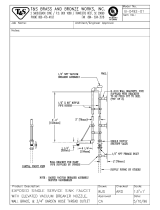
42005 Sold and Serviced By Label
42004 Burner Safety Warning Label
(High Voltage/Moving Parts Hazards)
42000 Burner Safety Warning Label
(Fire/Explosion Hazard - Reset Button)
42235 Burner Safety Warning Label
(Fire/Explosion Hazard -
Burner Installation and Service)
42321 Burner Model/Serial Number Label
42229 Logo/Burner Description Label
42023 Burner Power Label
42457 Made in USA / Pat Pending
Combination Label (on side)
42321
42235
42000
42005
42004
42023
42229
525 BURNER
I88603-B
Hazardous high voltage
and moving parts hazard.
To avoid electric shock and injury
from moving parts. turn power OFF
before opening cover.
WARNING
42004 Rev. 2
Fire and explosion hazard.
Do NOT press reset button until
you read and understand Reset
Procedures in Operator's Manual.
42000 Rev. 2
WARNING
42235 Rev. 2
Fire and explosion hazard.
This burner is to be installed ONLY on
Clean Burn products.
Only a qualied technician may maintain
and service this burner.
WARNING

Operator's Manual: Models CB-1750, CB-2500 & CB-3250
2-1
SECTION 2: UNPACKING
Before assembling your furnace, you must accomplish the following activities described in this section:
• Removing the Shipping Crate
• Unpacking and Inspecting All Components
• Warranty Registration
Removing the Shipping Crate
NOTE: Remove the shipping crate prior to assembly and installation of the furnace. DO NOT use the
crate as a platform for furnace installation!
1. Carefully remove the top boards of the shipping crate. Then remove the front, back, and side
panels of the shipping crate.
2. Carefully lift the furnace off the shipping pallet with a fork lift.
ATTENTION: DO NOT attempt to slide the furnace cabinet out of the shipping crate--you may
damage the furnace cabinet.
Unpacking and Inspecting All Components
Following is an itemized list of all components you should have received in your Clean Burn furnace
shipment. Open all shipping containers and inspect all components according to the list. Immediately
notify the freight company and your Clean Burn dealer in case of shipping damage or shortage(s). Keep
all components together so you will have them as needed for furnace assembly and installation.
Furnace Component List
ONE SKID containing:
• Furnace cabinet
• Items packed inside furnace cabinet (combustion chamber):
NOTE: Please refer to the procedure on the following page to remove these items.
• Target
• Hot air discharge assembly components plus hardware
• Furnace Accessories (items below in one box):
• Canister Filter
• Vacuum Gauge
• Check Valve and Check Valve Screen
• Wall Thermostat
• Barometric Damper
• Connector Block
• Burner Oil Line and Air Line Components
• Assorted bolts/ttings for assembly/installation of furnace components
• Operator's Manual Literature Packet (includes Tank Safety Label)
ITEMS PACKED IN INDIVIDUAL BOXES:
• Burner
• Blower Assembly
• Metering Pump (includes Suction Oil Line Fittings Package)
NOTE: You may have received additional boxes or skids if you ordered optional accessories.

Operator's Manual: Models CB-1750, CB-2500 & CB-3250
2-2
Warranty Registration
For proper warranty registration, Clean Burn requires that you ll out the provided warranty registration
card and return it within 30 days to:
CLEAN BURN WARRANTY REGISTRATION
Clean Burn, LLC.
4109 Capital Circle,
Janesville, WI 53546
Unpacking Items Packed Inside the Furnace
To unpack the items packed inside the furnace cabinet (in the combustion chamber), you will need to
open the combustion chamber door.
1. Remove the four nuts and washers which hold the combustion chamber door closed. Set the nuts
and washers aside in a safe place for later re-installation after the target has been installed
(Section 3).
2. Carefully swing the combustion chamber door open. Remove and inspect the components
packed inside.
3. Leave the door unfastened (open) for assembly/installation procedures to be accomplished in the
next section.
Figure 2A - Accessing the Combustion Chamber
COMBUSTION CHAMBER
CLEAN-OUT DOOR
I88436-A
/