
Revision Date
3/9/2012
Page 1 of 27
KIA Genuine Accessories
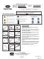
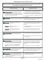
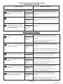
Instruction Symbols / Defi nitions
Note: Diffi culty stated above refl ects the minimum level of expertise required to install the accessory
( A ) Customer ( B ) Dealer Technician ( C ) Master Technician
Denotes warnings that may lead to
serious physical injury or vehicle
damage.
Denotes cautions to be taken to avoid
physical injury or electronic component
damage.
Denotes cautions to be taken to avoid
vehicle and component damage.
Denotes quality processes to be
checked prior to moving to the
next step.
Denotes specifi c tools that are neces-
sary to complete the step.
Denotes instructional steps
necessary to complete the
process.
Denotes safety equipment required to be used
such as a mask, goggles, rubber
gloves, and hearing protection.
N
O
T
E
Technical Support
For Authorized Dealers - (800) 667-5176
Hours: 9:00 a.m. - 6:00 p.m. EST Monday - Friday
9:00 a.m. - 3:00 p.m. EST Saturday
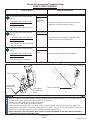
Basic Required Hand Tools
1/4” Drive Rachet
Phillips
Screwdriver
Trim Tool Wire Cutter
Pliers
1/4” Drive 10 mm
Socket
Alcohol Cleaner
1/4” Drive Torque
Wrench
1/4” Drive 6”
Extension
Mask
Rubber Gloves Hearing Protection
Googles
Center Fascia
Removal Tool
P/N: 09840-1E100
1/4” Drive 3/8”
Deep Socket
Flat Screwdriver
!
Ensure vehicle is equipped with automatic transmission, power door locks
and power windows. If the vehicle is not equipped with these options, do
not proceed. Ensure vehicle DOES have SMART KEY.
Vehicle Model Sorento (Push Button) Accessory Remote Engine Start
Model Year 2011~ Diffi culty ( B )
KMA Part No. U8560 1U010
Notes to the Installer:
Read the entire installation manual prior to beginning the
installation of the accessory.
Factory wire harness colors are subject to change, please use
the specifi ed pin # in the harness connector to identify the cor-
rect wire for T-Tap installation.
Ensure that the vehicle is properly protected in the area that
the accessory is to be installed.
To prevent vehicle damage, never place tools on top of painted
surfaces, seats, dash pad, console or fl oor carpet / mat.
Always wear appropriate safety gear to include gloves and eye
protection when required.
Prior to disconnecting the negative lead to the battery, note the
AM/FM and satellite set frequencies on the inspection page, if
applicable.
To prevent stress on the remote start wire harness, ensure the
tilt/telescopic steering column is fully extended, if equipped.
Ensure the transportation fuse is properly installed before
performing the function check on page 17.
P/N: 4280402, Rev. A

Revision Date
3/9/2012
Page 2 of 27
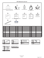
No. Qty. Descriptioin No. Qty. Description
1 1 Control Module/DNA 10 1 Warning Label
2 1 Dipole Antenna 11 6 15” Wire Tie (Large)
3 2 Transmitters 12 1 Foam Tape
4 1 Wire Harness
5 1 Immobilizer Interface
Module
6 1 Hardware Kit
7 1 Installation Instructions
8 1 Owner’s Guide
9 1 Quick reference Guide
Control Module P/N: U8560 00002
DNA P/N: U8560 00014
P/N: 00056 ADU50 P/N: U8560 00009
P/N: U8561 1U010
7
8
1 2 3 4 5
9
11
Owner’s
Guide
Quick
Reference
Guide
Installation
Instructions Warning Label
15” Wire Tie (Large)
8” Wire Tie (Small)15
A
Female T-Tap6
B
#10-24 Serrated Flange
Hex Bolt
1
C
1
D
Hardware Kit Total
26
#10-24 Serrated Flange
Hex Nut
P/N: XMIN-U8560 1U010-DP
KIA Genuine Accessories
Hardware
Kit
6
P/N: U8560 00010
10
12
Foam Tape
3
E
Foam Tape

Revision Date
3/9/2012
Page 3 of 27
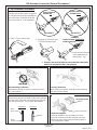
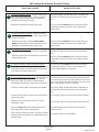
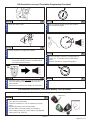
T-Tap Installation Procedure
Factory wire harness colors are subject
to change, please use the specifi ed pin
# in the harness connector to identify
the correct wire for T-Tap installation.
INCORRECT INCORRECT
Spade Terminal
Pointed Down
Spade Terminal
Pointed Up
1. Place T-Tap on vehicle wire.
2. Using pliers, close and crimp
T-Tap around vehicle wire.
3. Insert harness wire with
male spade terminal
end into the T-Tap.
CORRECT
Spade Terminal CENTERED
Inside Connector
Disconnecting Connectors
When disconnecting connectors, grasp the connec-
tors, not the wires.
Wire Colors
When a two-color wire is listed, the fi rst color indicates
the base color of the wire, the second color indicates
the color of the stripe. For example: Black/White.
Locking Connectors
When locking connectors, listen for a click indicating
they are securely locked.
Connector Diagrams
Connector diagrams may be shown on the har-
ness side or the terminal side, extreme care must
be taken to verify proper terminal location before a
T-Tap connection is made.
N
O GOO
D
NO GOOD
White
(Stripe Color)
Black
(Base Color)
Striped Wire
Solid Wire
Black
KIA Genuine Accessories (General Procedures)
** Extreme care must be taken to ensure that the male spade
terminal is inserted into the T-Tap properly.
Terminal End View
Harness End View

Revision Date
3/9/2012
Page 4 of 27
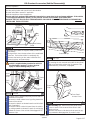
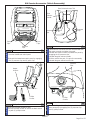
Vehicle Preparation
0
1/4” Drive Rachet, 10 mm Socket
Fuse Box
Warning Label
Negative Battery
Cable
1
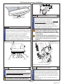
*Remove and isolate the negative battery cable from
the battery.
*Using alcohol, clean the top surface of the underhood
fuse box. Ensure the surface is completely dry.
*Remove the backing on the under hood label and
mount in place, as shown above.
Trim Tool
Pressure Clips
2
*Remove the driver’s side front door step sill trim panel
by inserting the trim removal tool under the trim panel
and prying upward to release the (4) pressure clips.
*Disconnect any connectors, if equipped.
*Carefully pull the weatherstrip away from the side of
the driver’s kick panel.
*Remove the hood release lever by pulling toward the
center of the vehicle.
*Remove the plastic nut located near the vehicle dash-
wall, if equipped.
*Remove the driver’s side kick panel from the vehicle
by pulling upward to release the push clip and prying
toward the center of the vehicle to disengage the (2)
pressure clips.
Trim Tool
3
*Disassembly Tip - Remove the fuse panel access
cover to assist in the removal of the driver’s side
dash end cap.
*Remove the driver’s side dash end cap panel by pry-
ing outward to disengage the (4) pressure clips.
Trim Tool
4
Push
Clip
Pressure
Clips
Plastic
Nut
Hood
Release
Lever
Pressure
Clips
KIA Genuine Accessories (Vehicle Disassembly)
Fuse Panel
Access Cover
N
O
T
E
N
O
T
E
N
O
T
E
N
O
T
E
*Clean hands.
*Set the parking brake and open driver’s door window.
*Record radio station presets, if applicable.
*Vehicle should be at room temperature.
*Ensure vehicle is equipped with automatic transmission, power door locks and power windows. If the vehicle
is not equipped with these options, do not proceed. Ensure vehicle DOES have SMART KEY.
*ENSURE THE TILT/TELESCOPIC STEERING WHEEL COLUMN IS FULLY EXTENDED AND LOCKED BEFORE
INSTALLING THIS ACCESSORY.
WARNING! Shock Hazard. Do not touch
vehicle’s negative battery terminal to vehicle’s
positive battery terminal. Serious physical
injury or vehicle damage may occur.
!

Revision Date
3/9/2012
Page 5 of 27
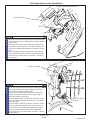
*Remove the (2) phillips screws from the side of the
lower dash fi nish panel.
Phillips Screwdriver
5
*Remove the lower dash fi nish panel by removing
the (2) phillips screws from the bottom of the panel.
Using a trim removal tool, carefully pry outward to
release the (5) pressure clips.
*Remove the OBDII connector from the panel.
*Disconnect the remaining connectors, if equipped.
Phillips Screwdriver, Trim Tool
6
*Remove the (5) 10 mm bolts and the (1) 10 mm nut
securing the steel knee bolster panel.
*Remove the steel knee bolster panel from the vehicle.
1/4” Drive Rachet, 1/4” Drive 6” Extension,
10 mm Socket
7
*Remove the (3) phillips screws securing the steer-
ing column shroud (1 underneath and 2 behind the
steering wheel). Turn the steering wheel for access.
*Release the tilt steering wheel adjuster lever.
*Pull down to separate (Use trim tool, if necessary)
and remove the lower steering column shroud from
the vehicle.
*Disconnect any connectors, if equipped.
8
Phillips
Screws
Phillips
Screws
Pressure
Clips
10 mm
Bolts
10 mm
Nut
Phillips
Screws
KIA Genuine Accessories (Vehicle Disassembly)
Phillips Screwdriver, Trim Tool
N
O
T
E
N
O
T
E
N
O
T
E
N
O
T
E

Revision Date
3/9/2012
Page 6 of 27
AUX
USB
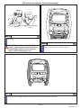
*Remove the Engine Start/Stop Button switch from the
dash assembly by removing (1) phillips screw.
*Using a trim removal tool, carefully pry outward to
release the (2) pressure clips.
*Disconnect the connector attached to the Engine
Start/Stop Button switch.
Phillips Screwdriver, Trim Tool
9
*Remove the (1) phillips screw securing the lower
heater air duct to the dashboard assembly.
*Remove the lower heater air duct from the vehicle.
10
ENGINE
START
STOP
Phillips
Screws
Phillips Screwdriver
Phillips
Screws
*Remove the gear selector access tab.
*Push straight down with a fl at screwdriver and shift the
gear selector into the drive position.
*Remove the gear selector handle by pulling it straight
up toward the headliner.
*Remove the center console/cup holder trim panel by
pulling upward at the cup holder area to disengage
the (6) pressure clips.
*Disconnect the connector and remove the trim panel
from the vehicle.
Flat Screwdriver, Trim Tool
11
*Disengage the (2) pressure clips and (4) push clips
securing the heated seat switch panel to the dash-
board assembly.
*Disconnect the connectors from the heated seat
switch panel and remove from the vehicle.
12
Pressure
Clips
Center Fascia Removal Tool
P/N: 09840-1E100
Pressure Clips
(Located In Corners)
Pressure
Clips
Gear Selector Access Tab
Push
Clips
Push
Clips
KIA Genuine Accessories (Vehicle Disassembly)
Insert Center Fascia
Removal Tool Here
CAUTION! Ensure parking brake is set.
Pressure
Clips
Heater
Air Duct
N
O
T
E
N
O
T
E
N
O
T
E
N
O
T
E
Center Fascia Removal Tool
Gear Selector
Handle

Revision Date
3/9/2012
Page 7 of 27
A/C
OFF
MODE
MODE
*Remove the (4) phillips screws securing the heater control unit.
*Disconnect the connectors and remove the heater control unit.
*Return the Gear Selector lever to the Park position.
Phillips Screwdriver
14
*Remove the (2) phillips screws securing the center fascia trim panel.
*Using a trim removal tool, carefully pry outward to release the (11) pressure clips.
*Disconnect the passenger airbag connector and remove the trim panel from the vehicle.
Phillips Screwdriver, Trim Tool
13
Pressure
Clips
Phillips
Screws
Pressure
Clips
Phillips Screws
KIA Genuine Accessories (Vehicle Disassembly)
Pressure
Clip
N
O
T
E
N
O
T
E
A/C
OFF
MODE
MODE
Phillips Screws

Revision Date
3/9/2012
Page 8 of 27
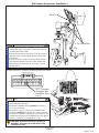
*Carefully pull the weatherstrip away from the driver’s
side “A” pillar.
*Remove the access cover and the single phillips
screw from the “A” pillar.
Trim Tool, Phillips Screwdriver
15
*Starting at the top, use a trim tool and remove the
driver’s side “A” pillar trim panel by inserting the tool
behind the panel and prying outward to release the
(2) pressure clips.
Trim Tool
16
CAUTION! Do not lose the (2) pressure clips.
Access Cover and Phillips Screw
KIA Genuine Accessories (Vehicle Disassembly)
Pressure Clips
N
O
T
E
N
O
T
E

Revision Date
3/9/2012
Page 9 of 27
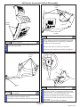
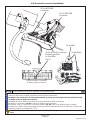
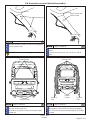
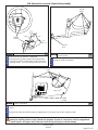
*Clean the area of the windshield where the antenna
will be mounted with an alcohol-based glass cleaning
solution. Ensure the glass surface is completely dry.
*Mount the the dipole antenna to the windshield
approximately 0.5” below the mirrors lowest
attachement point and/or any windshield electronic
gridwork. Remove protective backing. Press fi rmly to
ensure a good glass to adhesive bond.
Alcohol / Cleaner
1
*Route the antenna cable past the left side of the
dashboard and over to the fuse panel area.
*Plug the wire harness and the antenna cable into the
remote start module before mounting.
*Ensure all connectors are properly locked into posi-
tion.
3
CAUTION! Be careful not to bend/damage any of
the terminals inside the remote start module.
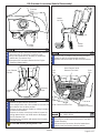
*Secure the upper right side tab of the remote start
module to the top hole in the factory brace support-
ing the fuse box with the supplied hex bolt and hex
nut. Secure the left side of the remote start module
to the factory harness with (1) large wire tie (Refer to
Step 15).
*Torque the hex nut to 52 inch pounds and trim off
excess wire tie.
1/4” Drive Rachet, 3/8” Socket,
Torque Wrench, Wire Cutter
4
10-Pin
24-Pin16-Pin
Antenna
Hex Bolt & Nut
(Hidden From View)
*Torque Hex Nut to 52 inch pounds
Wire Tie
(Installed in Step 15)
Fuse Box
KIA Genuine Accessories (Installation)
N
O
T
E
N
O
T
E
N
O
T
E
10"
9"
9"
*Wrap the antena cable with (3) pieces of supplied
black foam tape to ensure that the antenna will stay
in place after routing, as shown above.
*Route the antenna cable vertically on the right hand
side of the mirror mount up to the headliner. Tuck
the cable behind the headliner and down the
“A” pillar. Use (3) small wire ties to secure the
antenna cable to the factory harness located within
the “A” pillar. Trim off excess wire ties.
Trim Tool, Wire Cutter
2
WARNING! Air Bag system interference hazard.
DO NOT secure antenna cable to the Air Bag
components. Damage to the vehicle’s Air Bag
system may occur which could result in serious
physical injury.
CAUTION! If the vehicle is equipped with a sun-
roof, be careful not to place the wire ties around
the drain tube or the sunroof may not drain
properly.
N
O
T
E
!
Foam Tape

Revision Date
3/9/2012
Page 10 of 27
*Route the remote start harness 10-pin male and female
push button connectors upward to the Engine Start/Stop
button switch.
*Disconnect the factory male 10-pin M57 Engine Start/
Stop button switch connector, if not disconnected, and
plug in the corresponding remote start harness connec-
tors.
*Secure the female 10-pin remote start connector and
factory male M57 10-pin connector to the remote start
harness with (1) small wire tie, as shown. Trim off ex-
cess wire tie.
5
6
*Route the remote start harness 26-pin male and female
Smart Key module connectors upward to the Smart
Key module, located behind the radio.
*Disconnect the factory male 26-pin M10-A Smart Key
module connector and plug in the corresponding re-
mote start harness connectors.
*Wrap the factory male 26-pin M10-A connector and the
26-pin female remote start connector with (1) supplied
gray foam tape.
*Place the factory male 26-pin M10-A connector and the
26-pin female remote start harness connector on the
left hand side of the plastic dash assembly structure.
*Secure the remote start harness to the existing fac-
tory harness with (1) small wire tie, as shown. Trim off
excess wire tie.
Wire Cutter
Wire Cutter
Wire Tie
Smart Key Module
Male 26-Pin M10-A
Connector
Wire Tie
Steering Column
Engine Start/Stop Button Switch
KIA Genuine Accessories (Installation)
N
O
T
E
N
O
T
E

Revision Date
3/9/2012
Page 11 of 27
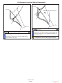
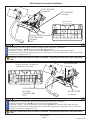
*Route the Red/Black, Gray, Green/Orange and Black
wires toward the fuse box.
*Locate the Red/Black wire in pin #16 of the 20-pin
I/P-F male connector.
*Using pliers, crimp a T-Tap on the Red/Black wire
located in pin #16 of the 20-pin I/P-F male connector.
*Connect the Red/Black (Hood Ajar Input) wire from the
remote start harness to the Red/Black wire (Pin #16 of
the I/P-F connector) by engaging the T-Tap.
***
*
3468910 2
1314151618 171920 12
Terminal End View
*Unplug connector, if necessary, to identify proper pin location
I/P-F Connector
Hood Ajar Wire
Red/Black Wire
Pin 16
8
Pliers
4-Pin Connectors
7
Wire Cutter
*Route the remote start harness 4-pin male and fe-
male brake switch connectors to the brake switch at
the top of the brake pedal.
*Disconnect the factory male 4-pin CHG 39 connector
and plug in the corresponding remote start harness
connectors.
*Secure the factory male connector and the remote
start harness female connector to the remote start
harness with (1) small wire tie, as shown. Trim off
excess wire tie.
Wire Tie
KIA Genuine Accessories (Installation)
CAUTION! Ensure the correct pin location is
identifi ed. There may be several wires of the
same/similar color.
N
O
T
E
N
O
T
E

Revision Date
3/9/2012
Page 12 of 27
*Locate the Gray wire in pin #17 of the 20-pin I/P-F
male connector.
*Using pliers, crimp a T-Tap on the Gray wire located in
pin #17 of the 20-pin I/P-F male connector.
*Connect the Gray (Rear Defroster Output) wire from
the remote start harness to the Gray wire (Pin #17 of
the I/P-F connector) by engaging the T-Tap.
9
Pliers
***
*
3468910 2
1314151618 171920 12
I/P-F Connector
Rear Defroster Wire
Gray Wire
Pin 17
*Unplug connector, if necessary, to identify proper pin location
Terminal End View
13
26
*
*
11
24
10
23
9
*
*
21
7
*
6
19
4
7
5
18
*
*
*
*
*
*
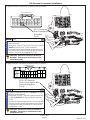
*Locate the Green/Orange wire in pin #10 of the 26-pin
BCM-FK male connector.
*Using pliers, crimp a T-Tap on the Green/Orange wire
located in pin #10 of the 26-pin BCM-FK male con-
nector.
*Connect the Green/Orange (Driver’s Door Switch Out-
put) wire from the remote start harness to the Green/
Orange wire (Pin #10 of the BCM-FK connector) by
engaging the T-Tap.
Terminal End View
*Unplug connector, if necessary, to identify proper pin location
BCM-FK Connector
Driver’s Door Switch Wire
Green/Orange Wire
Pin 10
10
Pliers
KIA Genuine Accessories (Installation)
CAUTION! Ensure the correct pin location is
identifi ed. There may be several wires of the
same/similar color.
CAUTION! Ensure the correct pin location is
identifi ed. There may be several wires of the
same/similar color.
N
O
T
E
N
O
T
E

Revision Date
3/9/2012
Page 13 of 27
15
13 12
25
23
11 10 9
21
78
19 17
54
**
*
*
*
***
*
*
*
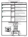
*Route the portion of the remote start harness containing the Lt. Blue, Red and Gray/Black wires along the right
side of the fuse box to the BCM (Located on the back side of the fuse box).
*Installation Tip - Remove the (2) 10 mm bolts and the (1) 10 mm nut securing the fuse box and tilt forward
for better access to the BCM connectors.
*Disengage the 26-pin BCM-ML connector from the backside of the BCM, if necessary.
*Locate the Lt. Blue wire in pin #21 of the 26-pin BCM-ML male connector.
*Using pliers, crimp a T-Tap on the Lt. Blue wire located in pin #21 of the 26-pin BCM-ML male connector.
*Connect the Lt. Blue (Parking Light Output) wire from the remote start harness to the Lt. Blue wire (Pin #21 of the
BCM-ML connector) by engaging the T-Tap.
*Unplug connector, if necessary,
to identify proper pin location
26-Pin BCM-ML Connector
Parking Light Wire
Lt. Blue Wire
Pin 21
11
1/4” Drive Rachet, 1/4” Drive 6” Extension, 10 mm Socket, Pliers
Terminal End View
KIA Genuine Accessories (Installation)
CAUTION! Ensure the correct pin location is identifi ed. There may be several wires of the same/similar
color.
22-Pin BCM-MN
Connector
16-Pin BCM-MM
Connector
N
O
T
E
10 mm Nut
10 mm Bolts

Revision Date
3/9/2012
Page 14 of 27
12
Pliers
*Unplug connector, if necessary, to identify proper pin location
*Disengage the 16-pin BCM-MM connector from the backside of the BCM, if necessary.
*Locate the Red wire in pin #8 of the 16-pin BCM-MM male connector.
*Using pliers, crimp a T-Tap on the Red wire located in pin #8 of the 16-pin BCM-MM male connector.
*Connect the Red (FOB Switch Output) wire from the remote start harness to the Red wire (Pin #8 of the BCM-MM
connector) by engaging the T-Tap.
865***21
16 15 14 11 10** *
16-Pin BCM-MM Connector
FOB Switch Wire
Red Wire
Pin 8
Terminal End View
*
*
*
*
*
*
*
2
4578
110
12
131416171819
22
*Disengage the 22-pin BCM-MN connector from the backside of the BCM, if necessary.
*Locate the Gray/Black wire in pin #2 of the 22-pin BCM-MN male connector.
*Using pliers, crimp a T-Tap on the Gray/Black wire located in pin #2 of the 22-pin BCM-MN male connector.
*Connect the Gray/Black (Horn Output) wire from the remote start harness to the Gray/Black wire (Pin #2 of the
BCM-MN connector) by engaging the T-Tap.
*Unplug connector, if necessary, to
identify proper pin location
22-Pin BCM-MN Connector
Horn Wire
Gray/Black Wire
Pin 2
Terminal End View
13
Pliers
KIA Genuine Accessories (Installation)
22-Pin BCM-MN
Connector
26-Pin BCM-ML
Connector
CAUTION! Ensure the correct pin location is identifi ed. There may be several wires of the same/similar
color.
16-Pin BCM-MM
Connector
26-Pin BCM-ML
Connector
N
O
T
E
N
O
T
E
CAUTION! Ensure the correct pin location is identifi ed. There may be several wires of the same/similar
color.

Revision Date
3/9/2012
Page 15 of 27
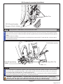
14
1/4” Drive Rachet, Torque Wrench, 10 mm Socket, Wire Cutter
*Locate the GF01 10 mm ground bolt in the left kick panel.
*Route the Black wire with ring terminal down along the factory wire harness to the factory GF01 ground location.
*Remove the 10 mm bolt. Position the Black wire with ring terminal over the bolt and reinstall with factory ground
wires.
*Torque to 10 lb-ft. (14 Nm).
*Secure the Black wire with ring terminal to the existing factory harness with (2) small wire ties, as shown above.
Trim off excess wire ties.
GF01 Ground Location
15
Wire Cutter
*Connect the disarm / programming button to the corresponding remote start module connector (if disconnected).
*Secure the disarm / programming button, CAN interface module and the remote start module to the existing fac-
tory harness with (3) large wire ties. Trim off excess wire ties.
*Secure the remote start antenna cable to the remote start harness, containing the Lt. Blue, Red and Gray/Black
wires with (1) small wire tie, as shown above. Trim off excess wire tie.
Large Wire Ties
Disarm/Programming
Button
Small Wire Tie
Wire Ties
KIA Genuine Accessories (Installation)
CAN Module Interface
N
O
T
E
N
O
T
E
*Torque to 10 lb-ft. (14 Nm)
WARNING! Engine Stall Hazard. To prevent stress on the remote start wire harness , ensure the tilt/
telescopic steering column is fully extended, if equipped. Ensure all connections are fully engaged and
locked in place. An engine stall could cause serious physical injury or vehicle damage.
!

Revision Date
3/9/2012
Page 16 of 27
KIA Genuine Accessories (Installation)
*Verify all connections are secure, per the installation
instructions.
*Reconnect the negative battery cable.
*Start the vehicle using the Engine Start/Stop button
on the dashboard (factory transmitter must be in the
vehicle) and verify that no Diagnostic Trouble Codes
have been triggered. Any DTCs should be reset
before proceeding to the next step.
1/4” Drive Rachet, 10 mm Socket
Fuse Box
Warning Label
Negative Battery
Cable
19
N
O
T
E
WARNING! Shock Hazard. Do not touch ve-
hicle’s negative battery terminal to vehicle’s
positive battery terminal. Serious physical
injury or vehicle damage may occur.
!
A/C
OFF
MODE
MODE
*Temporarily reconnect any connectors that were
disconnected from the heater control unit.
16
N
O
T
E
A/C
OFF
MODE
MODE
*Temporarily reconnect the passenger airbag connec-
tor attached to the center fascia trim panel.
17
N
O
T
E
A/C
OFF
MODE
MODE
*Temporarily reconnect any connectors that were dis-
connected from the heated seat switch panel.
18
N
O
T
E

Revision Date
3/9/2012
Page 17 of 27
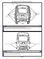
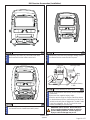
Remote Engine Start - Make sure the factory trans-
mitter is removed from the fob holder in the center
console and the engine hood, all doors and rear hatch
are closed. Activate the remote start by pressing the
start button 2 times within 3 seconds.
Hood Safety Switch - Open the driver’s door and
pull the hood release lever to release the hood.
Rear Defroster - Press the remote start button on
the transmitter one time while the vehicle is running.
Car Find Feature - Close the rear hatch and press
the red fi nd/panic button on the remote start
transmitter. Repeat this process twice.
The doors will lock, the parking lights will fl ash and
the horn will beep one time, then the vehicle will
crank and start. Once started, the parking lights will
turn on and stay on signifying the engine is running.
*The vehicle may require up to 30 seconds to start
successfully.
The engine/remote start will turn off immediately.
The hood should not have to be lifted to activate the
hood safety switch.
The parking lights will fl ash two times to indicate
that the vehicle is disarmed and unlock the driver’s
door only.
The parking lights will fl ash one time to indicate that
the vehicle is locked.
The parking lights will fl ash two times to indicate
that the vehicle is disarmed and unlock all doors.
The parking lights will fl ash one time. Locate the
rear defroster switch and verify that the indictator
portion of the switch is illuminated.
The parking lights will fl ash and the horn will beep 5
times. Subsequent presses within 5 seconds of the
fi rst press will beep the horn slightly louder.
Door Unlock - Press the unlock button on the
factory transmitter 1 time.
Door Lock - Press the lock button on the
factory transmitter 1 time.
Door Unlock - Press the unlock button on the
factory transmitter 2 times within 3 seconds.
Items To Be Checked
Results Of The Check
KIA Genuine Accessories (Function Check)
Hatch Safety Switch - Close the engine hood and
all doors. Activate the remote start by pressing the
start button 2 times within 3 seconds and proceed
to the rear of the vehicle with a factory transmitter.
Open the rear hatch using the hatch release
button located above the license plate area.
The doors will lock, the parking lights will fl ash and
the horn will beep one time, then the vehicle will
crank and start. Once started, the parking lights
will come on and stay on signifying the engine is
running.
The engine/remote start will turn off immediately.
Panic Feature - Press and hold the red fi nd/panic
button on the remote start transmitter for 3 seconds
to activate. Press the red fi nd/panic button a sec-
ond time to deactivate.
The parking lights will fl ash and the horn will beep
randomly for up to 30 seconds.
Ensure the parking brake is set and (1) factory transmitter and (1) remote start transmitter are
in hand before performing the Function Check.

Revision Date
3/9/2012
Page 18 of 27
Items To Be Checked Results Of The Check
KIA Genuine Accessories (Function Check)
Pre-start shut down (Hood) - Press the unlock but-
ton on the factory transmitter. Open the driver’s
door, pull the hood release lever to release the
hood and close the driver’s door.
Attempt to activate the remote engine start.
The parking lights will fl ash two times to indicate that
the vehicle is disarmed and unlock the driver’s door
only.
The horn will beep 2 times and the remote start will
not attempt to start the vehicle since it detects the
hood is open.
Pre-start shut down (Hatch) - Close the engine
hood and proceed to the rear of the vehicle with a
factory transmitter.
Open the rear hatch using the hatch release
button located above the license plate area and
attempt to activate the remote engine start.
The horn will beep 5 times and the remote start will
not attempt to start the vehicle since it detects the
hatch is open.
Pre-start shut down (Door) - Close the hatch and
press the unlock button on the factory transmitter.
Open the driver’s door and attempt to activate the
remote engine start.
The parking lights will fl ash two times to indicate that
the vehicle is disarmed and unlock the driver’s door
only.
The horn will beep 6 times and the remote start will
not attempt to start the vehicle since it detects a door
is open.
Pre-start shut down (Engine Start/Stop Button) -
Enter the vehicle and close the driver’s door. Press
and hold the Engine Start/Stop Button and attempt
to activate the remote engine start.
The horn will beep 7 times and the remote start will
not attempt to start the vehicle since it detects the
Engine Start/StopButton is pressed.
Remote Engine Start / Take Over - Exit the vehicle
and ensure the engine hood, all doors and rear
hatch are closed. Activate the remote start by
pressing the start button 2 times within 3 seconds.
Press the unlock button on the factory transmitter.
Open the driver’s door and enter the vehicle with a
factory transmitter.
Wait for the “Key Out” light to turn OFF on the
instrument cluster.
Press and HOLD the brake pedal and move the
gear select lever into the drive position.
Move the gear select lever back to the park position
and press the start button on the dashboard to turn
off the engine.
The doors will lock, the parking lights will fl ash and the
horn will beep one time, then the vehicle will crank and
start. Once started, the parking lights will come on and
stay on signifying the engine is running.
The parking lights will fl ash two times to indicate that
the vehicle is disarmed and unlock the driver’s door
only.
The “Key Out” light on the instrument cluster will fl ash.
The “Key Out” light on the instrument cluster turns OFF.
The parking lights will turn off and the vehicle will
remain running.
The engine will turn off immediately.

Revision Date
3/9/2012
Page 19 of 27
KIA Genuine Accessories (Vehicle Reassembly)
1/4” Drive Rachet, 10 mm Socket
Negative Battery
Cable
1
*Remove and isolate the negative battery cable from
the battery.
N
O
T
E
WARNING! Shock Hazard. Do not touch
vehicle’s negative battery terminal to vehicle’s
positive battery terminal. Serious physical
injury or vehicle damage may occur.
!
A/C
OFF
MODE
MODE
*Disconnect the passenger airbag connector and remove the center fascia trim panel.
3
N
O
T
E
A/C
OFF
MODE
MODE
*Disconnect the connectors from the heated seat
switch panel and remove from the vehicle
N
O
T
E
2

Revision Date
3/9/2012
Page 20 of 27
A/C
OFF
MODE
MODE
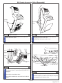
*Reinstall the driver’s side “A” pillar trim by engaging
the (2) pressure clips.
4
*Reinstall the single phillips screw and the access
cover.
*Reinstall the weatherstrip near the driver’s side “A”
pillar.
5
*Reconnect any connectors that were disconnected
from the heater control unit.
*Reinstall the (4) phillips screws securing the heater
control unit.
Phillips Screwdriver
6
Phillips
Screws
Pressure
Clips
Pressure Clips
Access Cover and
Phillips Screw
Phillips Screwdriver
KIA Genuine Accessories (Vehicle Reassembly)
Pressure Clips
N
O
T
E
N
O
T
E
N
O
T
E
Phillips Screws
A/C
OFF
MODE
MODE
*Reconnect the passenger airbag connector.
*Reinstall the center fascia trim panel by engaging
the (11) pressure clips and reinstalling the (2) phillips
screws.
Phillips Screwdriver
7
N
O
T
E
Pressure
Clips
Phillips Screws
CAUTION! Do not lose the (2) pressure clips.
Page is loading ...
Page is loading ...
Page is loading ...
Page is loading ...
Page is loading ...
Page is loading ...
Page is loading ...
-
 1
1
-
 2
2
-
 3
3
-
 4
4
-
 5
5
-
 6
6
-
 7
7
-
 8
8
-
 9
9
-
 10
10
-
 11
11
-
 12
12
-
 13
13
-
 14
14
-
 15
15
-
 16
16
-
 17
17
-
 18
18
-
 19
19
-
 20
20
-
 21
21
-
 22
22
-
 23
23
-
 24
24
-
 25
25
-
 26
26
-
 27
27


KIA Sorento 2011 User's Manual & Installation Instructions
- Type
- User's Manual & Installation Instructions
- This manual is also suitable for
Ask a question and I''ll find the answer in the document
Finding information in a document is now easier with AI
Related papers
-
KIA 2010 Owner's manual
-
KIA 2009 Owner's manual
-
KIA 2007 Sportage Owner's manual
-
-
-
-
KIA 2008 Sorento Owner's manual
-
-
-
KIA Sorento 2014 Features
Other documents
-
Brodit 215484 Datasheet
-
Summit Appliance WLM610P Installation guide
-
 TMI Products 1988-98 Chevy Truck Headliner Installation guide
-
CURT 55324 Installation guide
-
Hyundai J9F57 AC200 User manual
-
-
-
 Kleinn Air Horns RSJK Installation guide
-
Toro Replacement Hood Kit, XLS Lawn Tractor Installation guide
-
Ford 2021 F-150 Installation guide

