ESAB PT-37 Plasmarc Cutting Torches User manual

Category
Welding System
Type
User manual
PT-37
Plasmarc Cutting Torches
0558007622
Instruction Manual (EN)
P/N 0558004860 - PT-37 Torch with rack 4.5' (1.4 m)
P/N 0558004861 - PT-37 Torch with rack 17' (5.2 m)
P/N 0558004862 - PT-37 Torch with rack 25' (7.6 m)
P/N 0558004863 - PT-37 Torch with rack 50' (15.2 m)
P/N 0558004894 - PT-37 Torch w/o rack 4.5' (1.4 m)
P/N 0558004895 - PT-37 Torch w/o rack 17' (5.2 m)
P/N 0558004896 - PT-37 Torch w/o rack 25' (7.6 m)
P/N 0558004897 - PT-37 Torch w/o rack 50' (15.2 m)
6
This equipment will perform in conformity with the description thereof contained in this manual and accompa-
nying labels and/or inserts when installed, operated, maintained and repaired in accordance with the instruc-
tions provided. This equipment must be checked periodically. Malfunctioning or poorly maintained equipment
should not be used. Parts that are broken, missing, worn, distorted or contaminated should be replaced imme-
diately. Should such repair or replacement become necessary, the manufacturer recommends that a telephone
or written request for service advice be made to the Authorized Distributor from whom it was purchased.
This equipment or any of its parts should not be altered without the prior written approval of the manufacturer.
The user of this equipment shall have the sole responsibility for any malfunction which results from improper
use, faulty maintenance, damage, improper repair or alteration by anyone other than the manufacturer or a ser-
vice facility designated by the manufacturer.
BE SURE THIS INFORMATION REACHES THE OPERATOR.
YOU CAN GET EXTRA COPIES THROUGH YOUR SUPPLIER.
These INSTRUCTIONS are for experienced operators. If you are not fully familiar with the
principles of operation and safe practices for arc welding and cutting equipment, we urge
you to read our booklet, “Precautions and Safe Practices for Arc Welding, Cutting, and
Gouging,Form 52-529. Do NOT permit untrained persons to install, operate, or maintain
this equipment. Do NOT attempt to install or operate this equipment until you have read
and fully understand these instructions. If you do not fully understand these instructions,
contact your supplier for further information. Be sure to read the Safety Precautions be-
fore installing or operating this equipment.
CAUTION
USER RESPONSIBILITY
READ AND UNDERSTAND THE INSTRUCTION MANUAL BEFORE INSTALLING OR OPERATING.
PROTECT YOURSELF AND OTHERS!
7
SECTION TITLE PAGE
SECTION 1 SAFETY ...................................................................................................................................................9
1.0 Safety Precautions ..................................................................................................................................................................... 9
SECTION 2 DESCRIPTION ......................................................................................................................................................................... 11
2.0 Description ................................................................................................................................................................................11
2.1 Torch Specications: ...............................................................................................................................................................12
2.2 Optional Accessories: .............................................................................................................................................................14
2.3 Start-up Kits and Consumable Sets: .................................................................................................................................15
2.4 Consumable Breakdown: ......................................................................................................................................................16
SECTION 3 INSTALLATION ....................................................................................................................................................................... 17
3.0 Installation .................................................................................................................................................................................17
3.1 Torch Mounting ........................................................................................................................................................................17
3.2 Torch Installation ESP-101 ....................................................................................................................................................18
3.3 Torch Installation Powercut 900/1300/1600 ..................................................................................................................20
3.4 Torch Installation Remote Junction Box ..........................................................................................................................22
SECTION 4 OPERATION ............................................................................................................................................................................. 23
4.0 Cutting with the PT-37 ...........................................................................................................................................................23
4.1 Installing Consumables .........................................................................................................................................................23
4.2 Cut Data ......................................................................................................................................................................................25
4.2.1 Pressure Reduction for 4.5' and 17' Torch Lengths ......................................................................................................25
4.3 Operation of Power Source ..................................................................................................................................................25
TABLE OF CONTENTS
8
TABLE OF CONTENTS
9
SECTION 1 SAFETY PRECAUTIONS
1.0 Safety Precautions
Users of ESAB welding and plasma cutting equipment have the ultimate responsibility for ensuring that
anyone who works on or near the equipment observes all the relevant safety precautions. Safety precautions
must meet the requirements that apply to this type of welding or plasma cutting equipment. The following
recommendations should be observed in addition to the standard regulations that apply to the workplace.
All work must be carried out by trained personnel well acquainted with the operation of the welding or plasma
cutting equipment. Incorrect operation of the equipment may lead to hazardous situations which can result in
injury to the operator and damage to the equipment.
1. Anyone who uses welding or plasma cutting equipment must be familiar with:
- its operation
- location of emergency stops
- its function
- relevant safety precautions
- welding and / or plasma cutting
2. The operator must ensure that:
- no unauthorized person stationed within the working area of the equipment when it is started up.
- no one is unprotected when the arc is struck.
3. The workplace must:
- be suitable for the purpose
- be free from drafts
4. Personal safety equipment:
- Always wear recommended personal safety equipment, such as safety glasses, ame proof
clothing, safety gloves.
- Do not wear loose tting items, such as scarves, bracelets, rings, etc., which could become
trapped or cause burns.
5. General precautions:
- Make sure the return cable is connected securely.
- Work on high voltage equipment may only be carried out by a qualied electrician.
- Appropriate re extinquishing equipment must be clearly marked and close at hand.
- Lubrication and maintenance must not be carried out on the equipment during operation.
The IP code indicates the enclosure class, i.e. the degree of protection against penetration by solid objects or
water. Protection is provided against touch with a nger, penetration of solid objects greater than 12mm and
against spraying water up to 60 degrees from vertical. Equipment marked IP23S may be stored, but is not in-
tended to be used outside during precipitation unless sheltered.
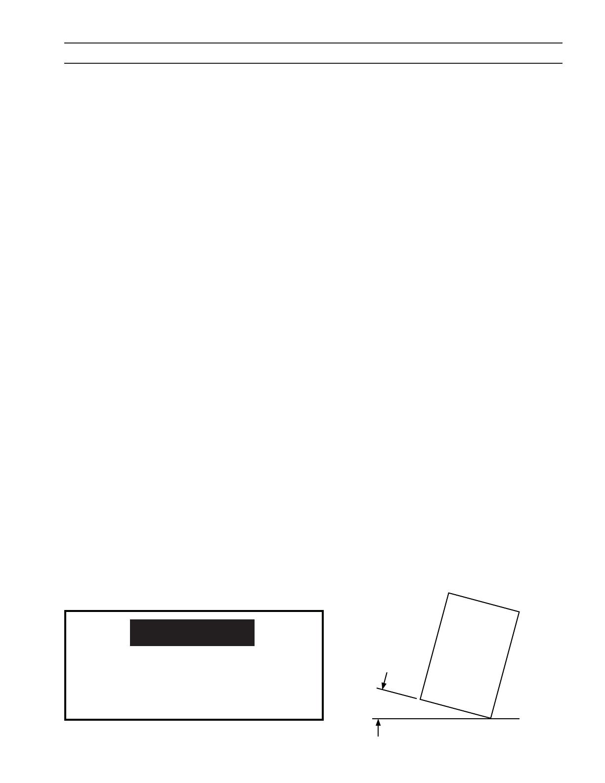
Enclosure Class
Maximum
Tilt Allowed
15°
CAUTION
If equipment is placed on a surface that slopes
more than 1, toppling over may occur. Personal
injury and / or signicant damage to equipment is
possible.
10
SECTION 1 SAFETY PRECAUTIONS
WELDING AND PLASMA CUTTING CAN BE INJURIOUS TO YOURSELF AND
OTHERS. TAKE PRECAUTIONS WHEN WELDING OR CUTTING. ASK FOR
YOUR EMPLOYER’S SAFETY PRACTICES WHICH SHOULD BE BASED ON
MANUFACTURERS’ HAZARD DATA.
ELECTRIC SHOCK - Can kill.
- Install and earth (ground) the welding or plasma cutting unit in accordance with applicable standards.
- Do not touch live electrical parts or electrodes with bare skin, wet gloves or wet clothing.
- Insulate yourself from earth and the workpiece.
- Ensure your working stance is safe.
FUMES AND GASES - Can be dangerous to health.
- Keep your head out of the fumes.
- Use ventilation, extraction at the arc, or both, to take fumes and gases away from your breathing zone
and the general area.
ARC RAYS - Can injure eyes and burn skin.
- Protect your eyes and body. Use the correct welding / plasma cutting screen and lter lens and wear
protective clothing.
- Protect bystanders with suitable screens or curtains.
FIRE HAZARD
- Sparks (spatter) can cause re. Make sure therefore that there are no inammable materials nearby.
NOISE - Excessive noise can damage hearing.
- Protect your ears. Use earmus or other hearing protection.
- Warn bystanders of the risk.
MALFUNCTION - Call for expert assistance in the event of malfunction.
READ AND UNDERSTAND THE INSTRUCTION MANUAL BEFORE INSTALLING OR OPERATING.
PROTECT YOURSELF AND OTHERS!
WARNING
This product is solely intended for plasma cutting. Any other use may
result in personal injury and / or equipment damage.
CAUTION
CAUTION
To avoid personal injury and/or equipment dam-
age, lift using method and attachment points
shown here.
11
SECTION 2 DESCRIPTION
2.0 Description
The patented PT-37 torch severs up to 1-1/4 inch material using air as the plasma and shielding gas. Utilizing a blowback
start and an electronically controlled pilot arc the PT-37 sets a new standard for starting reliability, cutting characteristics
and consumable life.
This manual is intended to provide the operator with all the information required to assemble, operate, and repair the PT-
37 Plasma Arc Cutting Torch. For additional safety precautions, process instructions, and system troubleshooting; refer to
the appropriate instruction manual for your Plasma Arc Cutting Package.
100% Duty Cycle for enhanced productivity allowing for continuous operation even at maximum thickness.
Utilizes a "drawn arc" to initiate the cut which eliminates high frequency interference from the starting circuits.
An optional remote starting system allows the torch to be located up to 150' (45m) away from the power sup-
ply.
Machined torch body with 1-3/8” (35mm) metal handle, available with and without 32-pitch rack to t industry
standard torch holders.
Robust machined torch components provide for reliability, durability and ease of maintenance.
Metal nozzle and shield stand up to the toughest cutting conditions.
Wear parts are available individually, in sets and in value packs which eases ordering and saves money.
DO NOT USE OXYGEN WITH THIS TORCH! A HAZARDOUS FIRE MAY
RESULT.
WARNING
THE PLASMA ARC CUTTING PROCESS EMPLOYS HIGH VOLTAGES.
CONTACT WITH "LIVE" PARTS OF THE TORCH AND MACHINE MUST
BE AVOIDED. ALSO, THE IMPROPER USE OF ANY OF THE GASES EM
PLOYED CAN PRESENT A SAFETY HAZARD. BEFORE BEGINNING OP
ERATION WITH THE PT37 TORCH, REFER TO THE SAFETY PRECAU
TIONS AND OPERATING INSTRUCTIONS IN THE APPROPRIATE POWER
SOURCE INSTRUCTION MANUAL.
USING THE PT37 TORCH ON ANY UNIT NOT EQUIPPED WITH A MAT
ING SAFETY INTERLOCK CIRCUIT MAY EXPOSE OPERATOR TO UNEX
PECTED HIGH VOLTAGE.
WARNING
12
2.1 Torch Specications:
PT-37 Torches:
PT-37 Torch with rack 4.5' (1.4 m) .....................................................................................................0558004860
PT-37 Torch with rack 17' (5.2 m) ......................................................................................................0558004861
PT-37 Torch with rack 25' (7.6 m) ......................................................................................................0558004862
PT-37 Torch with rack 50' (15.2 m) ...................................................................................................0558004863
PT-37 Torch w/o rack 4.5' (1.4 m) ......................................................................................................0558004894
PT-37 Torch w/o rack 17' (5.2 m) ......................................................................................................0558004895
PT-37 Torch w/o rack 25' (7.6 m) ......................................................................................................0558004896
PT-37 Torch w/o rack 50' (15.2 m) ...................................................................................................0558004897
SECTION 2 DESCRIPTION
Pierces and Cuts .............................................................................................................................. 3/4 in. (19 mm); severs 1-1/4 in. (32 mm)
Current Capacity ..................................................................................................................................................100 amps @ 100% duty cycle
Nominal Flow Rate (with 100 amp consumables) ................................................................ 490 cfh @ 80 psig (231 l/min @ 5.5 bar)
Length of Service Lines ...................................................................................4.5 ft (1.4 m) ,17 ft (5.2 m), 25 ft (7.6 m) or 50 ft (15.2 m)
Optional Service Line Extensions ...................................................................................................50 ft (15 m), 75 ft (23 m) 100 ft (30 m)
Dimensions:
18.1"
(460 mm)
1.38"
(35 mm)
12.0"
(305 mm)
13.7"
(348 mm)
4.4"
(112 mm)
13
SECTION 2 DESCRIPTION
Compatible ESAB Consoles:
ESP-101:
460 V Console...............................................................0558004880
380-400 V CE Console ...............................................0558005215
Powercut-1300:
208-230/460 V Mechanized Console ...................0558007881
208-230/460 V Mechanized Console Bilingual .... 0558007881F
400 V Mechanized Console .....................................0558008932
400 V CE Mechanized Console ..............................0558007882
575 V Mechanized Console Bilingual ..................0558008141
Powercut-1600:
208-230/460 V Mechanized Console ...................0558007883
208-230/460 V Mechanized Console Bilingual .... 0558007883F
400 V Mechanized Console .....................................0558008933
400 V CE Mechanized Console ...............................0558007884
575 V Mechanized Console Bilingual ..................0558008142
Powercut-900:
208/230 V Mechanized Console ............................ 0558008126
208/230 V Mechanized Console Bilingual .......0558008126F
230 V CE Mechanized Console ...............................0558008139
460 V Mechanized Console .....................................0558008130
400 V Mechanized Console .....................................0558008931
400 V CE Mechanized Console ...............................0558008138
575 V Mechanized Console Bilingual ..................0558008140
14
SECTION 2 DESCRIPTION
2.2 Optional Accessories:
Remote Junction Box .........................................................p/n 0558004887
Enables 50', 75' or 100' extension cables to be used between the ESP-
101 power supply and the existing torch service line. Not intended for use
with the mechanized versions of the PC-900/1300/1600 power supplies.
Extension Cable, 50 ft (15m) for Remote Junction Box .......................................................................................p/n 0558004888
75 ft (23m) for Remote Junction Box ......................................................................................p/n 0558009266
100 ft (30m) for Remote Junction Box ....................................................................................p/n 0558004889
Torch Holder Assembly ....................................................... p/n 0558005926
Plate Rider ................................................................................. p/n 0560936972
Used to maintain a constant stando while cutting thin materials or
using machines without automatic height control.
Gas Flow Measuring Kit ...........................................................................p/n 0558000739
Valuable troubleshooting tool allows measurement of the actual air ow through
the torch.
15
2.3 Start-up Kits and Consumable Sets:
SECTION 2 DESCRIPTION
PT-37 Start-Up Kits
0558004883
100 Amp
0558008889
90 Amp
0558008247
70 Amp
0558008248
60 Amp
Part No Description
10 10 10 10 0558004875 Electrode, Silver
1 1 1 1 0558005217 Gas Bae, 30-70 Amp
1 1 - - 0558004870 Gas Bae, 90 / 100 Amp
5 5 5 5 0558005218 Nozzle, 30-40 Amp
5 5 5 5 0558004878 Nozzle, 50 Amp
- - - 5 0558008417 Nozzle, 60 Amp
5 5 5 - 0558005219 Nozzle, 70 Amp
- 5 - - 0558007680 Nozzle, 90 Amp
5 - - - 0558004879 Nozzle, 100 Amp
1 1 1 1 0558006600 Retaining Cup with Threads
5 5 5 5 0558006603 Shield, 30-40 Amp
5 5 5 5 0558006602 Shield, 50-90 Amp
5 - - - 0558006601 Shield, 100 Amp
5 5 5 5 0558003694
O-ring, .674 ID x .103 W
Neoprene
1 1 1 1 0558000443
Grease, Silicon
Dow DC-111 (0.25 oz)
PT-37 Consumable Sets
0558004886
100 Amp
Value Pack
0558004885
100 Amp
0558008830
90 Amp
0558008369
70 Amp
0558008831
60 Amp
0558004884
50 Amp
0558008368
30-40 Amp
Part No Description
- - - - - - 1 0558005220 Electrode
10 1 1 1 1 1 - 0558004875 Electrode, Silver
- - - - - - 1 0558005218 Nozzle, 30-40 Amp
- - - - 1 1 - 0558004878 Nozzle, 50 Amp
- - - - - - - 0558008417 Nozzle, 60 Amp
- - - 1 - - - 0558005219 Nozzle, 70 Amp
- - 1 - - - - 0558007680 Nozzle, 90 Amp
15 1 - - - - - 0558004879 Nozzle, 100 Amp
16
SECTION 2 DESCRIPTION
2.4 Consumable Breakdown:
PT-37
P /N 0 55 8 9 5 4 0 4 1 - D 2 / 11
O-RING
0558101101
FUSE 2A 600V
0558001379
GREASE
0558000443
0558003694
O-RING
0558004875 05580048700558004879
0558006601
100A
0558006600
0558004875 05580052170558005219
0558006602
70A
0558006600
0558004875 05580052170558004878
0558006602
50A
0558006600
0558005220 05580052170558005218
0558006603
30-40A
0558006600
R E V I S I O N S
d a t el e t b y
P T- 3 7 T O R C H
L A B E L S / P K I T P T- 3 7
A r t w o r k n o . :
b y :
w h e r e u s e d :
d e s c r i p t i o n :
M - 0 5 5 8 9 5 4 0 4 1 - D
3/28/06 BLPOR
J E F F D AV I S
4/20/07 BLPA
7/22/08
10/13/09
2/12/11
JBD
PMD
PMD
B
C
D
Ÿ 10 ELECTRODES
Ÿ 1 GAS BAFFLE 90/100A
Ÿ 1 GAS BAFFLE 30-70A
Ÿ 5 O-RINGS
Ÿ 5 NOZZLES 100A
Ÿ 5 NOZZLES 70A
Ÿ 5 NOZZLES 50A
Ÿ 5 NOZZLES 30-40A
Ÿ 1 RETAINING CUP
Ÿ 5 SHIELDS 100A
Ÿ 5 SHIELDS 50-90A
Ÿ 5 SHIELDS 30-40A
Ÿ 10 ELECTRODES
Ÿ 1 GAS BAFFLE 30-70A
Ÿ 5 O-RINGS
Ÿ 5 NOZZLES 70A
Ÿ 5 NOZZLES 50A
Ÿ 5 NOZZLES 30-40A
Ÿ 1 RETAINING CUP
Ÿ 5 SHIELDS 50-90A
Ÿ 5 SHIELDS 30-40A
Ÿ 10 ELECTRODES
Ÿ 1 GAS BAFFLE 30-70A
Ÿ 5 O-RINGS
Ÿ 5 NOZZLES 60A
Ÿ 5 NOZZLES 50A
Ÿ 5 NOZZLES 30-40A
Ÿ 1 RETAINING CUP
Ÿ 5 SHIELDS 50-90A
Ÿ 5 SHIELDS 30-40A
START-UP KIT 100 AMP - 0558004883
START-UP KIT 70 AMP - 0558008247
START-UP KIT 60 AMP - 0558008248
Ÿ 30-40A 0558008368
Ÿ 50A 0558004884
Ÿ 60A 0558008831
Ÿ 70A 0558008369
Ÿ 90A 0558008830
Ÿ 100A 0558004885
CONSUMABLES SETS
1 ELECTRODE & 1 NOZZLE
Ÿ 100A 0558004886
CONSUMABLES VALUE PACK
10 ELECTRODES & 15 NOZZLES
17
SECTION 3 INSTALLATION
MAKE SURE POWER SWITCH ON CONSOLE IS IN OFF POSITION AND
PRIMARY INPUT POWER IS DEENERGIZED.
WARNING
3.0 Installation
3.1 Torch Mounting
7.2" (183 mm)
13.2" (335 mm)
Recommended Minimum
Recommended Maximum
With Torch Holder Assembly, P/N 0558005926
With Customer Supplied Holder
7.2" (183 mm)
13.2" (335 mm)
Recommended Minimum
Recommended Maximum
18.1"
(460 mm)
1.38"
(35 mm)
12.0"
(305 mm)
13.7"
(348 mm)
4.4"
(112 mm)
Torch Dimensions
Mounting
Area
6.0" (152 mm)
18
SECTION 3 INSTALLATION
Torch Cable
Power Cable Female Receptacle
Torch Lead Access Door
Air Hose
Torch Access Opening
1. Remove torch lead access door on the left side of the ESP-101.
2. Insert the torch cable through the torch access opening on
the front of the console.
3. Connect the air hose to the quick-connect tting.
4. Connect the torch cable male receptacle to the panel recep-
tacle. Check orientation of the sockets to ensure a correct t.
Power Cable Male Receptacle
3.2 Torch Installation ESP-101
19
5. Replace the torch lead access door.
Torch Lead Access Door
6. Insert the work cable into receptacle on the front of the con-
sole and turn clockwise until secure.
Work Cable
SECTION 3 INSTALLATION
20
SECTION 3 INSTALLATION
Panel Receptacle
Air Hose quick-connect tting
2. Connect the torch cable male receptacle to the panel receptacle.
Check orientation of the sockets to ensure a correct t.
3. Connect the air hose to the quick-connect tting. Place the strain relief in the square cutout in the front of
the console. Line up the groove of the strain relief with the half square cutout area.
Torch Cable Male
Receptacle
strain relief
square cutout
3.3 Torch Installation Powercut 900/1300/1600
1. Open torch lead access door on the front panel of the Powercut-1300/1600.
Torch Lead
Access
Door
21
Torch Lead Access Door
Work Cable
SECTION 3 INSTALLATION
4. Insert work cable into receptacle on the front of the console
and turn clockwise until secure.
5. Replace torch lead access door.
22
SECTION 3 INSTALLATION
3.4 Torch Installation Remote Junction Box
1. Remove cover. Mount box. Connect extension cable between the power supply and remote junction box.
Refer to remote junction box instruction manual. Note that the solenoid is wired to the power supply /
extension cable receptacle side of the box.
2. Connect the air hose to the quick-connect tting.
3. Connect the torch cable male receptacle to the panel receptacle. Check orientation of the sockets to en-
sure a correct t.
4. Replace cover.
23
SECTION 4 OPERATION
4.0 Cutting with the PT-37
Use the following procedures to cut with the PT-37 torch.
1. Make sure that the wall disconnect switch is on. Turn on the Power Switch to the cutting power source
console.
2. Set Pressure Regulator to 80 psig (5.5 bar).
3. Adjust torch stando to required initial / piercing height.
Note:
Torch damage and overheating can be
caused by loose parts. Arc tracking indi-
cates loose parts. Make sure retaining cup
is tightened fully. Parts damaged by arcing
will cause destruction of torch and must
be replaced.
Note:
Firm tightening of the electrode by hand is
sucient, the use of tools such as wrench-
es or pliers is not required or
recommended.
Note:
Ensure that the electrode/torch body seat
and piston are clean and free of dust or
dirt. Debris may prevent mating surfaces
from having solid contact.
4.1 Installing Consumables
Tests have shown that with proper use of the torch within rated operating conditions (especially arc current and
gas ow rate), the torch consumable parts do not become loose if they are rmly installed. Torch damage and
overheating can be caused by loose parts.
A. Tighten electrode and retaining/shield cup fully at each consumable change or inspection.
B. Check consumable tightness at beginning of each work period, even if everything was working normally at
the end of the previous period.
Nozzle
Electrode
Torch Body
Assembly
Retaining Cup
w/ Threads
Piston
Electrode/Torch
Body Seat
Gas Bae (30-70A)
Gas Bae (90/100A)
Shield
DO NOT USE OXYGEN WITH THIS TORCH! A HAZARDOUS FIRE MAY
RESULT.
DANGER
24
SECTION 4 OPERATION
  • Page 1 1
  • Page 2 2
  • Page 3 3
  • Page 4 4
  • Page 5 5
  • Page 6 6
  • Page 7 7
  • Page 8 8
  • Page 9 9
  • Page 10 10
  • Page 11 11
  • Page 12 12
  • Page 13 13
  • Page 14 14
  • Page 15 15
  • Page 16 16
  • Page 17 17
  • Page 18 18
  • Page 19 19
  • Page 20 20
  • Page 21 21
  • Page 22 22
  • Page 23 23
  • Page 24 24
  • Page 25 25
  • Page 26 26
  • Page 27 27
  • Page 28 28
  • Page 29 29
  • Page 30 30
  • Page 31 31
  • Page 32 32
  • Page 33 33
  • Page 34 34
  • Page 35 35
  • Page 36 36
  • Page 37 37
  • Page 38 38
  • Page 39 39
  • Page 40 40
  • Page 41 41
  • Page 42 42
  • Page 43 43
  • Page 44 44
  • Page 45 45
  • Page 46 46
  • Page 47 47
  • Page 48 48
  • Page 49 49
  • Page 50 50
  • Page 51 51
  • Page 52 52
  • Page 53 53
  • Page 54 54

ESAB PT-37 Plasmarc Cutting Torches User manual

Category
Welding System
Type
User manual

Ask a question and I''ll find the answer in the document

Finding information in a document is now easier with AI