Page is loading ...

®
Fire Ready Hood 1
®
Installation, Operation and Maintenance Manual
Please read and save these instructions for future reference. Read carefully before attempting to assemble, install,
operate or maintain the product described. Protect yourself and others by observing all safety information. Failure
to comply with these instructions will result in voiding of the product warranty and may result in personal injury
and/or property damage.
Document 483299
Model GRRS
Fire Ready Hood
NOTE
All service and maintenance on the fire suppression system
should be conducted by an authorized fire equipment
distributor. Do not tamper with fire suppression components
if not instructed to do so.
WARNING
To reduce the risk of fire, electric shock, or injury to
persons, observe the following:
• Use this product only in the manner intended by the manufacturer
(to cover domestic ranges used for domestic purposes).
• When cutting or drilling into wall or ceiling, do not damage
electrical wiring or other hidden utilities.
• Ducted exhaust fans must always be vented to the outdoors.
• Use only rigid, metal ductwork
• This unit must be properly grounded.
To reduce the risk of range top grease fire:
• Never leave the range unattended at high settings. Boil-overs
cause smoking and greasy spillovers that may ignite.
• Dense smoke from frying pans indicates cooking oil is near auto
ignition – turn the burner down or off.
• Always turn the hood fan ON when part of the cooking surface is
on
• Always make sure the hood grease filter is installed before cooking.
• Clean hood grease filter frequently. Do not allow grease to
accumulate on filter.
• Always use proper pan size. Use cookware appropriate for the size
of the surface element.
• Keep cooking areas clean and clear of combustible materials.
To reduce the risk of injury to persons in the event of a
range top grease fire, observe the following:*
• SMOTHER FLAMES with a close-fitting lid, cookie sheet, or metal
tray, then turn off the burner. BE CAREFUL TO PREVENT BURNS.
If the flames do not go out immediately, EVACUATE AND CALL
THE FIRE DEPARTMENT.
• NEVER PICK UP A FLAMING PAN. You may be burned.
• DO NOT USE WATER, including wet dishcloths or towels - violent
steam explosion will result.
* Based on “Kitchen Fire Safety Tips” published by NFPA.
AVERTISSEMENT
Pour réduire le risque d’incendie, de choc électrique ou
de blessure corporelle, respecter ce qui suit :
• Utiliser uniquement ce produit de la façon prévue par le fabricant
(pour couvrir les cuisinières domestiques utilisées à la maison).
• Lors de la découpe ou du perçage de murs ou plafonds, ne pas
endommager les câbles électriques et autres conduites masquées.
• Les caissons d’extraction à gaine d’évacuation doivent toujours
être évacués vers l’extérieur.
• Utiliser uniquement un réseau de gaine rigide, en métal.
• Cet appareil doit être bien raccordé à la terre.
Pour réduire le disque d’incendie de graisse sur le
dessus de la cuisinière :
• Ne jamais laisser la cuisinière sans surveillance à des réglages
élevés. Les débordements causent de la fumée et des
débordements de graisse qui peuvent s’enflammer.
• Une fumée dense provenant de poêles à frire indiquent que l’huile
à friture s’approche de son point d’inflammation spontanée. Régler
le bruleur plus bas ou l’éteindre.
• Toujours activer le ventilateur de la hotte lorsqu’une partie de la
surface de cuisson chauffe.
• Toujours s’assurer que le filtre de graisse de la hotte est installé
avant la cuisson.
• Nettoyer fréquemment la graisse du filtre de la hotte. Ne pas laisser
s’accumuler la graisse sur le filtre.
• Toujours utiliser la taille appropriée de poêle à frire. Utiliser une
batterie de cuisine proportionnelle à la surface de l’élément.
• Garder propre l’aire de cuisson et dégagée de toute matière
combustible.
Observer les points suivants pour réduire le risque
de blessures aux personnes advenant un incendie de
graisse sur le dessus de la cuisinière :*
• ÉTOUFFER LES FLAMMES à l’aide d’un couvercle ajusté,
d’une plaque à biscuits ou d’un plateau en métal, puis fermer le
brûleur. S’ASSURER D’ÉVITER DES BRÛLURES. Si les flammes
ne s’éteignent pas immédiatement, ÉVACUER LES LIEUX ET
APPELER LE SERVICE D’INCENDIE.
• NE JAMAIS SAISIR UNE POÊLE EN FLAMME. Vous pourriez vous
brûler.
• NE PAS UTILISER D’EAU, ni de linges à vaisselle ni de serviettes
mouillées car il pourrait se produire une violente explosion de
vapeur.
* Basé sur les « Kitchen Fire Safety Tips » (Conseils de sécurité sur
les incendies de cuisine) publiés par la NFPA
General Safety Information
Personnel should have a clear understanding of these
instructions and all applicable, current local and national
building and fire codes before installing this product.
PRG VERSION: V1.00
Listed to UL Subject 300A

Fire Ready Hood2
®
Receiving
Product should arrive in a large carton. Upon receiving
the product, check to ensure all items are accounted
for by referencing the delivery receipt or packing list.
Inspect each crate or carton for shipping damage before
accepting delivery. Alert the carrier of any damage
detected. The customer will make notation of damage
(or shortage of items) on the delivery receipt and all
copies of the bill of lading which is countersigned by the
delivering carrier. If damaged, immediately contact your
Greenheck Representative. Any physical damage to
the unit after acceptance is not the responsibility of the
manufacturer.
Unpacking
Verify that all required parts and the correct quantity of
each item have been received. If any items are missing,
report shortages to your local representative to arrange
for obtaining missing parts. Confirmation of shipment(s)
must be limited to only items on the bill of lading.
Parts Checklist
Hood with factory-installed Fire Suppression System
• Finished Top (optional)
• Ceiling Enclosures (optional)
Wall Mounting Bracket with J-Box
External Inline Fan (optional)
• One (1) 50 ft. Plug and Play Cable
Gas Disconnect (optional)
• 3/4 inch Gas Valve (plugs into gas shut off
assembly box)
• Gas Shut Off Assembly Box with 115VAC Range
Receptacle
• Two (2) 10 ft. Plug and Play Cables
Electrical Disconnect (optional)
• Electric Shut Off Assembly Box with 250VAC
Range Receptacle
• Two (2) 10 ft. Plug and Play Cables
Shipped Loose User Interface (optional)
• Recessed-Mount J Box
• One (1) 10 ft. Plug and Play Cable
Manual Pull Station (optional)
• One (1) 30 ft. Plug and Play Cable
Horn Strobe (optional)
• One (1) 8 ft. Cable
Wall Cap (optional)
K-Class Portable Fire Extinguisher (optional)
Fire Test Cylinder (optional)
Additional: Spare Fuse, Qty. 1 6A Fuse
Handling
Handle hood and accessories in such a manner as to
keep from scratching or chipping the coating. Damaged
finish may reduce ability of unit to resist corrosion.
Storage and Install Location Requirements
Units are protected against damage during shipment. If
the unit cannot be installed and operated immediately,
precautions need to be taken to prevent deterioration of
the unit during storage. The user assumes responsibility
of the unit and accessories while in storage. The
manufacturer will not be responsible for damage during
storage. The suggestions are provided solely as a
convenience to the user.
The ideal environment for the storage of units and
accessories is indoors, above grade, in a low humidity
atmosphere which is sealed to prevent the entry of
blowing dust, rain, or snow. Temperatures should be
evenly maintained between 32°F (0°C) and 120°F (49°C).
All accessories must be stored indoors in a clean, dry
location.
WARNING
The fire suppression system needs to be stored and
installed in locations where the temperature will not
fall below 32°F (0°C) and not exceed 120°F (49°C) for
proper operation.
AVERTISSEMENT
Le système extincteur d’incendie doit être entreposé
et installé dans des endroits où la température ne
descend pas sous 0°C (32°F) et ne dépasse pas
49°C (120°F) pour un bon fonctionnement.

Fire Ready Hood 3
®
Example: GRRS-W-36-T-E-O-N
Greenheck GRRS, wall mount, 36 inches long, with top
discharge, with electric element disconnect, fan
provided by others, NFPA 101 Compliant
GRRS - W- 36 - T - E - O - N
Model
Residential
Range
Suppression
Configuration
W - Wall
Ventilation
F - Integral Fan - Front Recirculation
R - Integral Fan - Rear Discharge
T - External Fan - Top Discharge
External Fan Type
D - Inline Duct
O - Fan by Others
NFPA 101 Compliance
X - Noncompliant
N - Compliant
Range Disconnect Type
E - Electric
G - Gas
Length
30 inches
36 inches
Model Number CodeTable of Contents
Receiving, Unpacking, Parts Checklist,
Handling and Storage ...................... 2
Model Number Code ......................... 3
Hood Exploded View ......................... 3
Ventilation and Fan Type Configurations ......... 4
Installation
General Information and Hood Weights ........ 7
Dimensional Data and Mounting Bracket ....... 8
Ductwork ................................ 9
Hood ................................... 9
External Fan ............................. 10
Range Disconnect
Gas / Electric ........................... 10
Accessories
Remote Mounted User Interface ............ 11
Finished Top ............................ 11
Ceiling Enclosures ....................... 11
Wall Cap ............................... 11
Manual Pull Station ...................... 12
Horn Strobe ............................ 12
Fire Extinguisher ........................ 12
Electrical Connections
Hood Power ............................. 13
Fan Power - Integral or External Fan .......... 13
Range Disconnect
Gas / Electric .........................13-14
Accessories
Remote Mounted User Interface ............ 15
Manual Pull Station ...................... 15
Horn Strobe ............................ 15
Other External Devices
Supply Fan Interlock Contacts ............. 15
Fire/Fault Contacts ...................... 15
Fan Calibration ........................... 16
Aiming the Nozzles ....................... 17
Operation ................................. 17
Unit Pre-Suppression Functions ............. 17
Arming the System. . . . . . . . . . . . . . . . . . . . . . . . 18
User Interface Navigation
Hood Lights Operation ................... 20
Fan Operation .......................... 20
Range Operation ........................ 20
Fire System Discharge .................... 21
System Faults .......................... 21
Service Settings .......................21-23
Fire Prevention Tips ...................... 23
Service and Maintenance
Accessing Internal Components ............. 24
Fire System Diagnostics ................... 25
Fire System Shut Off Sequence ............. 25
Fire System Detect Mode .................. 25
Fire Alarm Sequence ...................... 26
After Actuation ........................... 26
Routine Maintenance ....................... 27
Troubleshooting ..........................28-29
Parts List ................................. 29
Our Commitment .....................Backcover
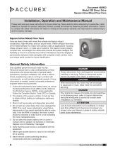
Hood Exploded View
TOUCHSCREEN
USER INTERFACE
WALL MOUNT
BRACKET
RECIRCULATING VENT
(FRONT RECIRCULATING MODEL)
WALL CLAMP
(QTY 2)
HOOD TEMPERATURE
SENSOR
LED LIGHTS
(QTY 2)
FIRE SUPPRESSION
TEMPERATURE SENSORS
(QTY 2)
GREASE FILTER
FIRE SUPPRESSION TANK AND
SOLENOID RELEASE
FIRE SUPPRESSION
CONTROL BOARD
INTERNAL EXHAUST FAN
(FOR FRONT RECIRCULATING
AND REAR DISCHARGE MODELS)
HOOD CONTROLS
(PLC, RELAYS, AND
TERMINAL BLOCKS)
FIRE SUPPRESSION
DROPS WITH NOZZLES
(QTY 2)
MODEL / SERIAL #
INFORMATION
STICKER

Fire Ready Hood4
®
Ventilation and Fan Type Configurations
External Fan | Top Discharge
(with Non-NFPA 101 Compliant Inline Fan)
External Fan | Top Discharge
(with Non-NFPA 101 Compliant Fan by Others)
Integral Fan | Rear Discharge
External Fan | Top Discharge
(with NFPA 101 Compliant 500 cfm Fan by Others)
Integral Fan | Front Recirculation
External Fan | Top Discharge
(with NFPA 101 Compliant 500 cfm Inline Fan)
Range Hood
(provided)
Airflow
Kitchen Cabinets
Soffit
External Inline Fan
(provided)
Roof Cap
(by others)
10 in. Ductwork
(by others)
12 in. to 10 in.
Transition
(by others)
10 in. to 12 in.
Transition
(by others)
10 in. Ductwork
(by others)
Range Hood
(provided)
Airflow
Kitchen Cabinets
Soffit
500 CFM
External Inline Fan
(provided)
Roof Cap
(by others)
12 in. Ductwork
(by others)
12 in. Ductwork
(by others)
Range Hood
(provided)
Airflow
Kitchen Cabinets
Soffit
Wall Cap
(optional)
5 in. x 12 in.
Ductwork
(by others)
Range Hood
(provided)
Airflow
Kitchen Cabinets
Soffit
Vent with Charcoal Filter
(provided)
Range Hood
(provided)
Airflow
Kitchen Cabinets
Soffit
10 in. Ductwork
(by others)
10 in. Ductwork
(by others)
External Fan
(by others)
8 in. to 10 in.
Transition
(by others)
8 in. to 12 in.
Transition
(by others)
8 in. to 10 in.
Transition
(by others)
Range Hood
(provided)
Airflow
Kitchen Cabinets
Soffit
12 in. Ductwork
(by others)
12 in. Ductwork
(by others)
500 CFM
External Fan
(by others)
8 in. to 12 in.
Transition
(by others)
External Fan | Top Discharge
(with Non-NFPA 101 Compliant Inline Fan)
External Fan | Top Discharge
(with NFPA 101 Compliant 500 CFM Inline Fan)
Integral Fan | Rear Discharge Integral Fan | Front Recirculation
External Fan | Top Discharge
(with Non-NFPA 101 Compliant Fan by Others)
External Fan | Top Discharge
(with NFPA 101 Compliant Fan by Others)
EXTERNAL FAN
CONFIGURATIONS
INTEGRAL FAN
CONFIGURATIONS
Range Hood
(provided)
Airflow
Kitchen Cabinets
Soffit
External Inline Fan
(provided)
Roof Cap
(by others)
10 in. Ductwork
(by others)
12 in. to 10 in.
Transition
(by others)
10 in. to 12 in.
Transition
(by others)
10 in. Ductwork
(by others)
Range Hood
(provided)
Airflow
Kitchen Cabinets
Soffit
500 CFM
External Inline Fan
(provided)
Roof Cap
(by others)
12 in. Ductwork
(by others)
12 in. Ductwork
(by others)
Range Hood
(provided)
Airflow
Kitchen Cabinets
Soffit
Wall Cap
(optional)
5 in. x 12 in.
Ductwork
(by others)
Range Hood
(provided)
Airflow
Kitchen Cabinets
Soffit
Vent with Charcoal Filter
(provided)
Range Hood
(provided)
Airflow
Kitchen Cabinets
Soffit
10 in. Ductwork
(by others)
10 in. Ductwork
(by others)
External Fan
(by others)
8 in. to 10 in.
Transition
(by others)
8 in. to 12 in.
Transition
(by others)
8 in. to 10 in.
Transition
(by others)
Range Hood
(provided)
Airflow
Kitchen Cabinets
Soffit
12 in. Ductwork
(by others)
12 in. Ductwork
(by others)
500 CFM
External Fan
(by others)
8 in. to 12 in.
Transition
(by others)
External Fan | Top Discharge
(with Non-NFPA 101 Compliant Inline Fan)
External Fan | Top Discharge
(with NFPA 101 Compliant 500 CFM Inline Fan)
Integral Fan | Rear Discharge Integral Fan | Front Recirculation
External Fan | Top Discharge
(with Non-NFPA 101 Compliant Fan by Others)
External Fan | Top Discharge
(with NFPA 101 Compliant Fan by Others)
EXTERNAL FAN
CONFIGURATIONS
INTEGRAL FAN
CONFIGURATIONS

Fire Ready Hood 5
®
Wiring Diagram: Electric Disconnect
U1
C1/2
G
GO
NO1
GND
U4
BK 14GA
L1
N
GND
110-120V/60HZ/1PH
CONTROL POWER
H1 = LINE
N1 = NEUTRAL
GND = GROUND
W
14GA
NO5
C6
RD 14GA
NO6
U3
24VAC
115VAC
TR1
40VA
T3
GND
U1
NO4
U2
NO3
XT3;BL 18GA
FIRE
STATUS
POWER
RESET
GAS STATUS
NC6
FU1
6A
BK 14GA
BK 14GA
O
18GA
BR 18GA
J3
DISP.
3
4
2
1
+VTERM
-
+
O
GR 22GA
RD 22GA
W 22GA
Y 22GA
BL 22GA
BK 22GA
10FT TOUCH SCREEN
CABLE,
LIGHT BLUE
TOUCH SCREEN
USER
INTERFACE
U2
1
2
3
4
5
6
1
2
SHUT-OFF
BLDG
ALARM
REMOTE
PULL
1
2
1
2
1
2
1
2
3
4
1
2
3
4
2
1
1
2
1
2
SENSE1
SENSE2
GND
GAUGE
VALVE
1
2
3
4
1
2
3
4
5
6
1
2
3
4
RD
BK
SENSOR 1 CABLE
RD
BK
SENSOR 2 CABLE
T2
T1
PRESSURE GAUGE
CABLE
TANK
PRESSURE
GAUGE
W
BK
SOLENOID CABLE
TANK
SOLENOID
W
BK
Y 18GA
BL 18GA
BL 18GA
GAS RESET
1
2
3
4
5
6
1
2
3
4
5
6
FIRE
DETECT
N/C
N/O
COM
COM
N/O
N/C
TROUBLE
DETECT
Y 18GA
BL 18GA
BL 18GA
2
3
1
4
5
6
2
3
1
4
5
6
BL 18GA
Y 18GA
Y 18GA
BL 18GA
3FT INTERNAL
CABLE,
BROWN (386601)
1
2
3
4
1
2
3
4
G502INT
1
2
3
4
5
6
7
8
1
2
3
4
5
6
7
8
9
9
10FT RANGE SHUTOFF CABLE 1, GUARDIAN
GR
RD
Y
BK
BL
W
RANGE
DISCONNECT 1
RANGE
DISCONNECT 2
DISCONNECT
CONTROL
BOX
10FT RANGE SHUTOFF CABLE 2, RED (386600)
7
6
5
4
3
2
1
2
3
1
4
5
6
7
8
Y
BL
RD
GR
Y
BL
RD
GR
W 14GABK 14GA
BL 18GA
RD 14GA
RD 14GA
Y 18GA
8
POWER
TRIP
GR
U10
NO2
BK RD
Y 18GA
BK 14GA
C3/4/5
BL 18GA
(115VAC SPDT)
GND
Y 18GA
BL Y
BL 18GA
Y 18GA
Y 18GA
1FT FML FAN HRNSS,
ORANGE
(386596)
2
3
1
4
1FT ML FAN HRNSS,
ORANGE
(386595)
3
4
1
2
BK
14GA
4
2
1
3
3
4
2
1
H1
N1
GND
24H 24C
GND
B1
L
L
(HOOD LIGHT 1)
(HOOD LIGHT 2)
R
A1 A2
R2
H1
N1
GND
R2
11
14
T1-B
T1-A
R
A1 A2
R3
R
A1 A2
R4
24C
BL 18GA Y 18GA
R
A1 A2
R5
C6
NO6
NC6
CM
BL 18GA
R1
11
14
PR1
PR2
GR1
GR2
GL1
GL2
PT1
PT2
GR
GND
R3
11
12
BL 18GA
BL 18GA
R3
21
24
BL 18GA
R
A1 A2
R1
BL 18GA
R5
11
14
BL 18GA
CHANGES BASED ON FAN SELECTION
1
2
W
BK
PULL STATION CABLE
30FT
MANUAL PULL STATION
RANGE
4-PRONG
POWER
CORD
RANGE 14-50R RECEPTACLE
(208-240VAC 50A POWER TO RANGE)
BK
BK
W
GN
INTERNAL
EC FAN
BR 115V (L1)
BL 115V (N)
Y 22GA (E1)
GR/YW (GND)
WH 22GA
RD 22GA
BL 22GA

Fire Ready Hood6
®
U1
C1/2
G
GO
NO1
GND
U4
BK 14GA
L1
N
GND
110-120V/60HZ/1PH
CONTROL POWER
H1 = LINE
N1 = NEUTRAL
GND = GROUND
W
14GA
NO5
C6
RD 14GA
NO6
U3
24VAC
115VAC
TR1
40VA
T3
GND
U1
NO4
U2
NO3
XT3;BL 18GA
FIRE
STATUS
POWER
RESET
GAS STATUS
NC6
FU1
6A
BK 14GA
BK 14GA
O
18GA
BR 18GA
J3
DISP.
3
4
2
1
+VTERM
-
+
O
GR 22GA
RD 22GA
W 22GA
Y 22GA
BL 22GA
BK 22GA
10FT TOUCH SCREEN
CABLE,
LIGHT BLUE
TOUCH SCREEN
USER
INTERFACE
U2
1
2
3
4
5
6
1
2
SHUT-OFF
BLDG
ALARM
REMOTE
PULL
1
2
1
2
1
2
1
2
3
4
1
2
3
4
2
1
1
2
1
2
SENSE1
SENSE2
GND
GAUGE
VALVE
1
2
3
4
1
2
3
4
5
6
1
2
3
4
RD
BK
SENSOR 1 CABLE
RD
BK
SENSOR 2 CABLE
T2
T1
PRESSURE GAUGE
CABLE
TANK
PRESSURE
GAUGE
W
BK
SOLENOID CABLE
TANK
SOLENOID
W
BK
Y 18GA
BL 18GA
BL 18GA
GAS RESET
1
2
3
4
5
6
1
2
3
4
5
6
FIRE
DETECT
N/C
N/O
COM
COM
N/O
N/C
TROUBLE
DETECT
Y 18GA
BL 18GA
BL 18GA
2
3
1
4
5
6
2
3
1
4
5
6
BL 18GA
Y 18GA
Y 18GA
BL 18GA
3FT INTERNAL
CABLE,
BROWN (386601)
1
2
3
4
1
2
3
4
G502INT
1
2
3
4
5
6
7
8
1
2
3
4
5
6
7
8
9
9
10FT RANGE SHUTOFF CABLE 1, GUARDIAN
GR
RD
Y
BK
BL
W
RANGE
DISCONNECT 1
RANGE
DISCONNECT 2
DISCONNECT
CONTROL
BOX
10FT RANGE SHUTOFF CABLE 2, RED (386600)
7
6
5
4
3
2
1
2
3
1
4
5
6
7
8
Y
BL
RD
GR
Y
BL
RD
GR
W 14GABK 14GA
BL 18GA
RD 14GA
RD 14GA
Y 18GA
8
POWER
TRIP
GR
U10
NO2
BK RD
Y 18GA
BK 14GA
C3/4/5
BL 18GA
(115VAC SPDT)
GND
Y 18GA
BL Y
BL 18GA
Y 18GA
Y 18GA
1FT FML FAN HRNSS,
ORANGE
(386596)
2
3
1
4
1FT ML FAN HRNSS,
ORANGE
(386595)
3
4
1
2
BK
14GA
4
2
1
3
3
4
2
1
H1
N1
GND
24H 24C
GND
B1
L
L
(HOOD LIGHT 1)
(HOOD LIGHT 2)
R
A1 A2
R2
H1
N1
GND
R2
11
14
T1-B
T1-A
R
A1 A2
R3
R
A1 A2
R4
24C
BL 18GA Y 18GA
R
A1 A2
R5
C6
NO6
NC6
CM
BL 18GA
R1
11
14
PR1
PR2
GR1
GR2
GL1
GL2
PT1
PT2
GR
GND
R3
11
12
BL 18GA
BL 18GA
R3
21
24
BL 18GA
R
A1 A2
R1
BL 18GA
R5
11
14
BL 18GA
CHANGES BASED ON FAN SELECTION
1
2
W
BK
PULL STATION CABLE
30FT
MANUAL PULL STATION
GAS
VALVE
1
2
1
2
33
GR
W
BK
GR
W
BK
5FT
CABLE
GAS
VALVE
RANGE 5-15 RECEPTACLE (115VAC 15A
POWER TO RANGE)
BK
W
GN
RANGE
3-PRONG
POWER
CORD
INTERNAL
EC FAN
BR 115V (L1)
BL 115V (N)
Y 22GA (E1)
GR/YW (GND)
WH 22GA
RD 22GA
BL 22GA
Wiring Diagram: Gas Disconnect

Fire Ready Hood 7
®
Installation
It is recommended that before drywall is hung, all
electrical cables that need to be run within the wall
should be run through the wall to their corresponding
components. Mount the control j-box to line up with
the right corner of the hood mounting bracket and run
cables for these components into this box through the
grommets. Confirm all critical mounting points will need
to be secured through studs or utilize dry wall hangers.
Hood weight should be supported by at least two (2)
studs. Hood needs to be centered above the range
and within the height requirements shown. Make sure
that with integral fan – rear discharge configurations,
the studs and control j-box (see picture on right) do not
interfere with the rear discharge duct.
After drywall is hung, affix mounting bracket to wall
using the necessary field provided fasteners through the
critical mounting points.
WARNING
Failure to affix the mounting bracket
to studs correctly can lead to
structural damage and/or serious
injury. The structural integrity of
the wall is the responsibility of the
contractor.
Hood Weight
30 inches 86 lbs.
36 inches 93 lbs.
AVERTISSEMENT
Si le support de fixation est mal posé
sur les montants, il peut y avoir des
dommages structuraux et/ou de
graves blessures. L’entrepreneur est
responsable de l’intégrité structurale
du mur.
Poids de la hotte
76 cm
(30 po)
39 kg
(86 lb)
91,4 cm
(36 po)
42,2 kg
(93 lb)
Minimum Spacing:
24 inches
Maximum Spacing:
30 inches
Measure vertical distance
from bottom of hood to
cooking surface
Measure vertical distance
from bottom of hood to
cooking surface
Hood to Cooking Surface
Spacing Recommendation
6.00"
3.50"
4.00"
Ø2.000"
x3
Ø1.000"
x2
Control J-Box Dimensions
Bottom View of Box
Top View of Box

Fire Ready Hood8
®
B
A
A
A
A
E
B
C
A
A
E
B
D D
B
A
A
A
A
E
B
C
A
A
E
B
D D
B
A
A
A
A
E
B
C
A
A
E
B
D D
A
C
A
A
A
A
E
A
A
E
D D
A
A
A
C
A
A
A
A
E
A
A
E
D D
A
A
A
C
A
A
A
A
E
A
A
E
D D
A
A
A
30" Integral Fan | Front Recirculation
30" Integral Fan | Rear Discharge
30" External Fan | Top Discharge
36" Integral Fan | Front Recirculation
36" Integral Fan | Rear Discharge
36" External Fan | Top Discharge
MOUNTING BRACKET KEY
A. CRITICAL MOUNTING POINTS (MUST BE SECURED TO STUDS
OR DRY WALL HANGERS)
B. UTILIZE ONE OF THESE TWO CRITICAL POINTS FOR SECURING
TO STUD OR DRY WALL HANGERS (THREE TOTAL)
C. LOCATION FOR FACTORY PROVIDED 4" H x 6" W x 3.5" D
CONTROL J-BOX
D. HOOD SUPPORT TABS
E. HOOD LATCH CONNECTIONS
NOTES:
1) BEFORE MOUNTING, SITUATE MOUNTING BRACKET ON WALL,
MAKING SURE CRITICAL MOUNTING POINTS ARE MET AND
DISTANCE FROM BOTTOM OF BRACKET TO COOKING SURFACE
IS BETWEEN 24 AND 30 INCHES.
2) CUT OUT SPACE IN WALL FOR FACTORY PROVIDED CONTROL
J-BOX AND SECURE IN PLACE.
3) SECURE MOUNTING BRACKET TO WALL USING THE PROPER
FIELD PROVIDED FASTENERS USING CRITICAL MOUNTING
POINTS SHOWN ABOVE.
33.625
12.275
27.625
12.275
1.650
3.000
4.625
8.375
3.375
2.376
1.813
4.000
4.000
5.114
1.223
1.813
4.000
2.750
27.625
12.275
1.650
3.000
4.625
8.375
3.375
2.376
1.813
4.000
4.000
5.114
1.223
1.813
4.000
2.750
27.625
12.275
1.650
3.000
4.625
8.375
3.375
2.376
1.813
4.000
4.000
5.114
1.223
1.813
4.000
6.389
1.650
3.000
4.625
4.813
4.000
4.000
8.375 7.248 2.376
5.114
1.223
4.813
4.000
33.625
12.275
1.650
3.000
4.625
4.813
4.000
4.000
8.375 7.248 2.376
5.114
1.223
4.813
4.000
33.625
12.275
1.650
3.000
4.625
4.813
4.000
4.000
8.375 7.248 2.376
5.114
1.223
4.813
4.000
2.750 2.750
6.389
5 x 12 INCH
REAR DISCHARGE
FAN DUCT
5 x 12 INCH
REAR DISCHARGE
FAN DUCT
5 x 12 INCH
REAR DISCHARGE
FAN DUCT
5 x 12 INCH
REAR DISCHARGE
FAN DUCT
B
A
A
A
A
E
B
C
A
A
E
B
D D
B
A
A
A
A
E
B
C
A
A
E
B
D D
B
A
A
A
A
E
B
C
A
A
E
B
D D
A
C
A
A
A
A
E
A
A
E
D D
A
A
A
C
A
A
A
A
E
A
A
E
D D
A
A
A
C
A
A
A
A
E
A
A
E
D D
A
A
A
30" Integral Fan | Front Recirculation
30" Integral Fan | Rear Discharge
30" External Fan | Top Discharge
36" Integral Fan | Front Recirculation
36" Integral Fan | Rear Discharge
36" External Fan | Top Discharge
MOUNTING BRACKET KEY
A. CRITICAL MOUNTING POINTS (MUST BE SECURED TO STUDS
OR DRY WALL HANGERS)
B. UTILIZE ONE OF THESE TWO CRITICAL POINTS FOR SECURING
TO STUD OR DRY WALL HANGERS (THREE TOTAL)
C. LOCATION FOR FACTORY PROVIDED 4" H x 6" W x 3.5" D
CONTROL J-BOX
D. HOOD SUPPORT TABS
E. HOOD LATCH CONNECTIONS
NOTES:
1) BEFORE MOUNTING, SITUATE MOUNTING BRACKET ON WALL,
MAKING SURE CRITICAL MOUNTING POINTS ARE MET AND
DISTANCE FROM BOTTOM OF BRACKET TO COOKING SURFACE
IS BETWEEN 24 AND 30 INCHES.
2) CUT OUT SPACE IN WALL FOR FACTORY PROVIDED CONTROL
J-BOX AND SECURE IN PLACE.
3) SECURE MOUNTING BRACKET TO WALL USING THE PROPER
FIELD PROVIDED FASTENERS USING CRITICAL MOUNTING
POINTS SHOWN ABOVE.
33.625
12.275
27.625
12.275
1.650
3.000
4.625
8.375
3.375
2.376
1.813
4.000
4.000
5.114
1.223
1.813
4.000
2.750
27.625
12.275
1.650
3.000
4.625
8.375
3.375
2.376
1.813
4.000
4.000
5.114
1.223
1.813
4.000
2.750
27.625
12.275
1.650
3.000
4.625
8.375
3.375
2.376
1.813
4.000
4.000
5.114
1.223
1.813
4.000
6.389
1.650
3.000
4.625
4.813
4.000
4.000
8.375 7.248 2.376
5.114
1.223
4.813
4.000
33.625
12.275
1.650
3.000
4.625
4.813
4.000
4.000
8.375 7.248 2.376
5.114
1.223
4.813
4.000
33.625
12.275
1.650
3.000
4.625
4.813
4.000
4.000
8.375 7.248 2.376
5.114
1.223
4.813
4.000
2.750
2.750
6.389
5 x 12 INCH
REAR DISCHARGE
FAN DUCT
5 x 12 INCH
REAR DISCHARGE
FAN DUCT
5 x 12 INCH
REAR DISCHARGE
FAN DUCT
5 x 12 INCH
REAR DISCHARGE
FAN DUCT
30 Inch Integral Fan | Front Recirculation 36 Inch Integral Fan | Front Recirculation
B
A
A
A
A
E
B
C
A
A
E
B
D D
B
A
A
A
A
E
B
C
A
A
E
B
D D
B
A
A
A
A
E
B
C
A
A
E
B
D D
A
C
A
A
A
A
E
A
A
E
D D
A
A
A
C
A
A
A
A
E
A
A
E
D D
A
A
A
C
A
A
A
A
E
A
A
E
D D
A
A
A
30" Integral Fan | Front Recirculation
30" Integral Fan | Rear Discharge
30" External Fan | Top Discharge
36" Integral Fan | Front Recirculation
36" Integral Fan | Rear Discharge
36" External Fan | Top Discharge
MOUNTING BRACKET KEY
A. CRITICAL MOUNTING POINTS (MUST BE SECURED TO STUDS
OR DRY WALL HANGERS)
B. UTILIZE ONE OF THESE TWO CRITICAL POINTS FOR SECURING
TO STUD OR DRY WALL HANGERS (THREE TOTAL)
C. LOCATION FOR FACTORY PROVIDED 4" H x 6" W x 3.5" D
CONTROL J-BOX
D. HOOD SUPPORT TABS
E. HOOD LATCH CONNECTIONS
NOTES:
1) BEFORE MOUNTING, SITUATE MOUNTING BRACKET ON WALL,
MAKING SURE CRITICAL MOUNTING POINTS ARE MET AND
DISTANCE FROM BOTTOM OF BRACKET TO COOKING SURFACE
IS BETWEEN 24 AND 30 INCHES.
2) CUT OUT SPACE IN WALL FOR FACTORY PROVIDED CONTROL
J-BOX AND SECURE IN PLACE.
3) SECURE MOUNTING BRACKET TO WALL USING THE PROPER
FIELD PROVIDED FASTENERS USING CRITICAL MOUNTING
POINTS SHOWN ABOVE.
33.625
12.275
27.625
12.275
1.650
3.000
4.625
8.375
3.375
2.376
1.813
4.000
4.000
5.114
1.223
1.813
4.000
2.750
27.625
12.275
1.650
3.000
4.625
8.375
3.375
2.376
1.813
4.000
4.000
5.114
1.223
1.813
4.000
2.750
27.625
12.275
1.650
3.000
4.625
8.375
3.375
2.376
1.813
4.000
4.000
5.114
1.223
1.813
4.000
6.389
1.650
3.000
4.625
4.813
4.000
4.000
8.375 7.248 2.376
5.114
1.223
4.813
4.000
33.625
12.275
1.650
3.000
4.625
4.813
4.000
4.000
8.375 7.248 2.376
5.114
1.223
4.813
4.000
33.625
12.275
1.650
3.000
4.625
4.813
4.000
4.000
8.375 7.248 2.376
5.114
1.223
4.813
4.000
2.750 2.750
6.389
5 x 12 INCH
REAR DISCHARGE
FAN DUCT
5 x 12 INCH
REAR DISCHARGE
FAN DUCT
5 x 12 INCH
REAR DISCHARGE
FAN DUCT
5 x 12 INCH
REAR DISCHARGE
FAN DUCT
B
A
A
A
A
E
B
C
A
A
E
B
D D
B
A
A
A
A
E
B
C
A
A
E
B
D D
B
A
A
A
A
E
B
C
A
A
E
B
D D
A
C
A
A
A
A
E
A
A
E
D D
A
A
A
C
A
A
A
A
E
A
A
E
D D
A
A
A
C
A
A
A
A
E
A
A
E
D D
A
A
A
30" Integral Fan | Front Recirculation
30" Integral Fan | Rear Discharge
30" External Fan | Top Discharge
36" Integral Fan | Front Recirculation
36" Integral Fan | Rear Discharge
36" External Fan | Top Discharge
MOUNTING BRACKET KEY
A. CRITICAL MOUNTING POINTS (MUST BE SECURED TO STUDS
OR DRY WALL HANGERS)
B. UTILIZE ONE OF THESE TWO CRITICAL POINTS FOR SECURING
TO STUD OR DRY WALL HANGERS (THREE TOTAL)
C. LOCATION FOR FACTORY PROVIDED 4" H x 6" W x 3.5" D
CONTROL J-BOX
D. HOOD SUPPORT TABS
E. HOOD LATCH CONNECTIONS
NOTES:
1) BEFORE MOUNTING, SITUATE MOUNTING BRACKET ON WALL,
MAKING SURE CRITICAL MOUNTING POINTS ARE MET AND
DISTANCE FROM BOTTOM OF BRACKET TO COOKING SURFACE
IS BETWEEN 24 AND 30 INCHES.
2) CUT OUT SPACE IN WALL FOR FACTORY PROVIDED CONTROL
J-BOX AND SECURE IN PLACE.
3) SECURE MOUNTING BRACKET TO WALL USING THE PROPER
FIELD PROVIDED FASTENERS USING CRITICAL MOUNTING
POINTS SHOWN ABOVE.
33.625
12.275
27.625
12.275
1.650
3.000
4.625
8.375
3.375
2.376
1.813
4.000
4.000
5.114
1.223
1.813
4.000
2.750
27.625
12.275
1.650
3.000
4.625
8.375
3.375
2.376
1.813
4.000
4.000
5.114
1.223
1.813
4.000
2.750
27.625
12.275
1.650
3.000
4.625
8.375
3.375
2.376
1.813
4.000
4.000
5.114
1.223
1.813
4.000
6.389
1.650
3.000
4.625
4.813
4.000
4.000
8.375 7.248 2.376
5.114
1.223
4.813
4.000
33.625
12.275
1.650
3.000
4.625
4.813
4.000
4.000
8.375 7.248 2.376
5.114
1.223
4.813
4.000
33.625
12.275
1.650
3.000
4.625
4.813
4.000
4.000
8.375 7.248 2.376
5.114
1.223
4.813
4.000
2.750
2.750
6.389
5 x 12 INCH
REAR DISCHARGE
FAN DUCT
5 x 12 INCH
REAR DISCHARGE
FAN DUCT
5 x 12 INCH
REAR DISCHARGE
FAN DUCT
5 x 12 INCH
REAR DISCHARGE
FAN DUCT
30 Inch Integral Fan | Rear Discharge 36 Inch Integral Fan | Rear Discharge
B
A
A
A
A
E
B
C
A
A
E
B
D D
B
A
A
A
A
E
B
C
A
A
E
B
D D
B
A
A
A
A
E
B
C
A
A
E
B
D D
A
C
A
A
A
A
E
A
A
E
D D
A
A
A
C
A
A
A
A
E
A
A
E
D D
A
A
A
C
A
A
A
A
E
A
A
E
D D
A
A
A
30" Integral Fan | Front Recirculation
30" Integral Fan | Rear Discharge
30" External Fan | Top Discharge
36" Integral Fan | Front Recirculation
36" Integral Fan | Rear Discharge
36" External Fan | Top Discharge
MOUNTING BRACKET KEY
A. CRITICAL MOUNTING POINTS (MUST BE SECURED TO STUDS
OR DRY WALL HANGERS)
B. UTILIZE ONE OF THESE TWO CRITICAL POINTS FOR SECURING
TO STUD OR DRY WALL HANGERS (THREE TOTAL)
C. LOCATION FOR FACTORY PROVIDED 4" H x 6" W x 3.5" D
CONTROL J-BOX
D. HOOD SUPPORT TABS
E. HOOD LATCH CONNECTIONS
NOTES:
1) BEFORE MOUNTING, SITUATE MOUNTING BRACKET ON WALL,
MAKING SURE CRITICAL MOUNTING POINTS ARE MET AND
DISTANCE FROM BOTTOM OF BRACKET TO COOKING SURFACE
IS BETWEEN 24 AND 30 INCHES.
2) CUT OUT SPACE IN WALL FOR FACTORY PROVIDED CONTROL
J-BOX AND SECURE IN PLACE.
3) SECURE MOUNTING BRACKET TO WALL USING THE PROPER
FIELD PROVIDED FASTENERS USING CRITICAL MOUNTING
POINTS SHOWN ABOVE.
33.625
12.275
27.625
12.275
1.650
3.000
4.625
8.375
3.375
2.376
1.813
4.000
4.000
5.114
1.223
1.813
4.000
2.750
27.625
12.275
1.650
3.000
4.625
8.375
3.375
2.376
1.813
4.000
4.000
5.114
1.223
1.813
4.000
2.750
27.625
12.275
1.650
3.000
4.625
8.375
3.375
2.376
1.813
4.000
4.000
5.114
1.223
1.813
4.000
6.389
1.650
3.000
4.625
4.813
4.000
4.000
8.375 7.248 2.376
5.114
1.223
4.813
4.000
33.625
12.275
1.650
3.000
4.625
4.813
4.000
4.000
8.375 7.248 2.376
5.114
1.223
4.813
4.000
33.625
12.275
1.650
3.000
4.625
4.813
4.000
4.000
8.375 7.248 2.376
5.114
1.223
4.813
4.000
2.750 2.750
6.389
5 x 12 INCH
REAR DISCHARGE
FAN DUCT
5 x 12 INCH
REAR DISCHARGE
FAN DUCT
5 x 12 INCH
REAR DISCHARGE
FAN DUCT
5 x 12 INCH
REAR DISCHARGE
FAN DUCT
B
A
A
A
A
E
B
C
A
A
E
B
D D
B
A
A
A
A
E
B
C
A
A
E
B
D D
B
A
A
A
A
E
B
C
A
A
E
B
D D
A
C
A
A
A
A
E
A
A
E
D D
A
A
A
C
A
A
A
A
E
A
A
E
D D
A
A
A
C
A
A
A
A
E
A
A
E
D D
A
A
A
30" Integral Fan | Front Recirculation
30" Integral Fan | Rear Discharge
30" External Fan | Top Discharge
36" Integral Fan | Front Recirculation
36" Integral Fan | Rear Discharge
36" External Fan | Top Discharge
MOUNTING BRACKET KEY
A. CRITICAL MOUNTING POINTS (MUST BE SECURED TO STUDS
OR DRY WALL HANGERS)
B. UTILIZE ONE OF THESE TWO CRITICAL POINTS FOR SECURING
TO STUD OR DRY WALL HANGERS (THREE TOTAL)
C. LOCATION FOR FACTORY PROVIDED 4" H x 6" W x 3.5" D
CONTROL J-BOX
D. HOOD SUPPORT TABS
E. HOOD LATCH CONNECTIONS
NOTES:
1) BEFORE MOUNTING, SITUATE MOUNTING BRACKET ON WALL,
MAKING SURE CRITICAL MOUNTING POINTS ARE MET AND
DISTANCE FROM BOTTOM OF BRACKET TO COOKING SURFACE
IS BETWEEN 24 AND 30 INCHES.
2) CUT OUT SPACE IN WALL FOR FACTORY PROVIDED CONTROL
J-BOX AND SECURE IN PLACE.
3) SECURE MOUNTING BRACKET TO WALL USING THE PROPER
FIELD PROVIDED FASTENERS USING CRITICAL MOUNTING
POINTS SHOWN ABOVE.
33.625
12.275
27.625
12.275
1.650
3.000
4.625
8.375
3.375
2.376
1.813
4.000
4.000
5.114
1.223
1.813
4.000
2.750
27.625
12.275
1.650
3.000
4.625
8.375
3.375
2.376
1.813
4.000
4.000
5.114
1.223
1.813
4.000
2.750
27.625
12.275
1.650
3.000
4.625
8.375
3.375
2.376
1.813
4.000
4.000
5.114
1.223
1.813
4.000
6.389
1.650
3.000
4.625
4.813
4.000
4.000
8.375 7.248 2.376
5.114
1.223
4.813
4.000
33.625
12.275
1.650
3.000
4.625
4.813
4.000
4.000
8.375 7.248 2.376
5.114
1.223
4.813
4.000
33.625
12.275
1.650
3.000
4.625
4.813
4.000
4.000
8.375 7.248 2.376
5.114
1.223
4.813
4.000
2.750 2.750
6.389
5 x 12 INCH
REAR DISCHARGE
FAN DUCT
5 x 12 INCH
REAR DISCHARGE
FAN DUCT
5 x 12 INCH
REAR DISCHARGE
FAN DUCT
5 x 12 INCH
REAR DISCHARGE
FAN DUCT
30 Inch External Fan | Top Discharge 36 Inch External Fan | Top Discharge
1. Before mounting, situate mounting bracket on wall
making sure critical mounting points are met and
distance from bottom of bracket to cooking surface is
between 24 and 30 inches.
2. Cut out space in wall for factory provided control
j-box and secure in place.
3. Secure mounting bracket to wall using the proper
field provided fasteners through all critical mounting
points shown in the drawings. Select fasteners that
will properly support the total weight of the hood
(hood weight shown on page 7).
Mounting Bracket Key
A
Critical mounting points must be secured to studs or
drywall hangers
B
Utilize one of these two critical points for securing to
stud or drywall hangers. (three total)
C
Location for factory provided 4 inch high x 6 inch wide
x 3-1/2 inches deep control j-box
D
Hood support tabs
E
Hood latch connections
Dimensional Data
Dimensions shown are in inches.

Fire Ready Hood 9
®
Hood
1. Remove hood from crating. Remove the grease filter.
2. Carefully lift it onto the lower hood tabs on the wall mounting bracket.
2. While holding the hood up, hook the safety cable to the chain link on the mounting bracket and screw nut to close
the link. The hood is now in the service position.
3. To put the hood into operation position, lift the hood up, and one at a time re-hook the clamps and pull the clamps
tight until they lock. Make sure the safety bolt lever is located inside the notch in the hood mounting bracket. See
page 22 for pictures and more information.
4. When all construction is complete, remove protective plastic sheeting from hood stainless steel. Clean (using
alcohol and rag) and polish (using stainless steel polish) the hood. When cleaning or polishing, be sure to wipe
with the grain and not against it.
Hood Length
(in.)
NFPA 101
Compliance
Ventilation
External Fan
Type
CFM
Duct Size
(Minimum)
Duct Length
(Maximum)
30
No Integral Fan – Front Recirculating Not applicable 250 Not applicable Not applicable
No Integral Fan – Rear Discharge Not applicable 250 5 x 12 in. 2 ft.
No External Fan - Top Discharge Inline 250
10 in. round
(diameter)
35 ft.
No External Fan - Top Discharge Fan by Others 250
10 in. round
(diameter)
External fan by others should be sized
based on hood and duct static pressure
Yes Integral Fan - Rear Discharge Not applicable 500 5 x 12 in. 2 ft.
Yes External Fan - Top Discharge Inline 500
12 in. round
(diameter)
35 ft.
Yes External Fan - Top Discharge Fan by Others 500
12 in. round
(diameter)
External fan by others should be sized
based on hood and duct static pressure
36
No Integral Fan – Front Recirculating Not applicable 300 Not applicable Not applicable
No Integral Fan – Rear Discharge Not applicable 300 5 x 12 in. 2 ft.
No External Fan - Top Discharge Inline 300
10 in. round
(diameter)
35 ft.
No External Fan - Top Discharge Fan by Others 300
10 in. round
(diameter)
External fan by others should be sized
based on hood and duct static pressure
Yes Integral Fan - Rear Discharge Not applicable 500 5 x 12 in. 2 ft.
Yes External Fan - Top Discharge Inline 500
12 in. round
(diameter)
35 ft.
Yes External Fan - Top Discharge Fan by Others 500
12 in. round
(diameter)
External fan by others should be sized
based on hood and duct static pressure
All ductwork will need to be provided in the field. Installing ductwork must be done by qualified person(s) in
accordance with all applicable codes and standards, including fire-rated construction. All ductwork, per IMC Section
505 should be constructed of sheet metal, have smooth inner walls, be air tight, and be independent of all other
exhaust ductwork systems.
To minimize static pressure losses and promote adequate airflow, minimize duct run lengths where possible.
For external fan configurations, duct should be connected to the 8 inch collar adapter on the hood mounting bracket.
Transitions should be utilized to expand duct to duct size minimum requirements noted in table above.
Ductwork (if applicable)
Running ductwork will be required for hoods configured for external fans. A small rectangular piece of duct spanning
the width of the wall will be required for integral fan – rear discharge configurations (discharging through the back
wall). For integral fan - rear discharge, the duct cannot be permanently attached to the hood, as the hood does drop
into a service potion, so we recommend using a high temperature gasket where the back of the hood and rear duct
through the wall meet to provide a good seal during operation. Check the individual hood drawings to see what fan
type is provided with your system.

Fire Ready Hood10
®
External Fan (if applicable)
External Fan – Inline
Install fan vertically or horizontally in ductwork running
between the unit and roof cap. Make sure the fan
installed with the airflow arrow on the side of the fan
directed away from the hood (to the outside).
For best results, use as few elbows or transitions as
possible. If necessary, long radius elbows or bends are
recommended.
To attach ductwork, use duct tape at inlet and outlet to
assure a good seal. If using fan clamps, attach clamps
and insert screws through clamp into inlet and outlet
flanges.
External Fan – Fan By Others
Follow all installation instructions provided with the fan.
CAUTION
Use sheet metal screws to secure ductwork to inlet
and outlet. It is critical that the screw penetrate the
metal of the flange, but not so far as to bind the
impeller. It may be necessary to angle screws away
from impeller.
ATTENTION
Utiliser des vis autotaraudeuses pour fixer le réseau de
gaines à l’entrée et à la sortie. Il est essentiel que la vis
pénètre le métal du rebord, mais pas assez pour faire
saisir la turbine. Il peut être nécessaire de faire dévier
les vis pour les éloigner de la turbine.
3/4"
6.25
10.00
9.19
8.25
5.60
RANGE
115 VOLT - 15 AMP
ALARM / STROBE
115 VOLT - 5 AMP
2.70
GAS FLOW
VALVE RESET
POWER RESET
FUEL ACTIVATION
CONTACT RATING
12 VAC - 5 AMP
AUXILIARY INTERFACE
CONTACT RATING
115 VAC - 5 AMP
2.70
60 IN. (5 FT)
POWER CORD
WITH 5-15R PLUG
3/4 IN. NPT
GAS
VALVE
18 IN. (1.5 FT)
WHIP TO
GAS VALVE
60 IN. (5 FT)
GAS
VALVE
CORD
3.00
3.32
LEFT SIDE
VIEW
RIGHT SIDE
VIEW
TOP VIEW
GAS SHUT OFF
ASSEMBLY BOX
(FRONT VIEW)
GAS /ELEC DISC
CABLE
Dimensions shown
are in inches.
Range Disconnect
Gas (if applicable)
1. Locate gas shut off assembly box and gas valve.
2. Using the four (4) appropriate sized fasteners, mount
and fasten gas shut off assembly box behind range
through mounting holes provided. Unit dimensions
shown:
3. If not already done, plug gas valve 1.5 ft. whip into
5 ft. gas valve cord coming off of bottom of the gas
shut off assembly box. Install ¾ inch (NPT fittings)
gas valve in-line with gas line to range.
4. Follow electrical installation instructions for gas range
disconnect on pages 13 and 14.
Electric (if applicable)
1. Locate electric shut off assembly box.
2. Electric shut off assembly should be situated behind
the range (on floor) or in cabinet next to range. Unit
dimensions shown:
3. Follow electrical installation instructions for electric
range disconnect on page 14.
9.00
9.38
3.75
5.32
3.75
ELECTRIC SHUT OFF
ASSEMBLY BOX
(TOP VIEW)
BACK VIEW
LEFT SIDE
VIEW
RIGHT SIDE
VIEW
30" (2.5 FT)
POWER CORD
WITH 14-50 PLUG
Dimensions shown are in inches.
NOTE
Cables provided to connect the gas and electric
assembly boxes back to the hood are 10 ft. long. Do
not mount the gas shut off assembly box too far away
from the hood, as these cables will not reach. Make
sure to mount shutoff within 5ft of 115VAC 5-15 outlet.

Fire Ready Hood 11
®
Accessories
Remote Mounted User Interface (if applicable)
Skip these steps if the user interface is factory mounted
on the hood.
1. Recess mount the user interface box near hood
(cable provided is 10 feet in length).
2. Follow electrical installation instructions for remote
mounted user interface on pages 13 and 14.
NOTE
To comply with ADA standards, interface (if mounted
on an unobstructed wall) must be a max of 48 inches
off of the finished floor.
Finished Top (if applicable)
A finished top can be included with all integral fan
configurations when there are no cabinets covering the
top of the hood. If provided with a finished top, the top
piece will be attached to the hood when shipped.
1. Remove the finished top piece after mounting the
hood. Once the hood is fully installed and armed,
fasten the finished top piece to the top of the hood
using fasteners provided.
Ceiling Enclosures (if applicable)
Ceiling enclosures may be included with the system
to close off the top of the hood when configured for
external fan – top discharge, to hide ductwork if no
kitchen cabinets enclose the top of the hood.
1. Remove screws that attach enclosure mounts to
enclosure panels.
2. Fasten enclosure through pre-drilled holes to wall
using appropriate field provided fasteners.
3. Attach enclosure panels to enclosure mounts using
the screws removed in step 1.
Wall Cap (if applicable)
A wall cap with built in birdscreen and damper may
be provided for internal fan – rear discharge hood
configurations that exit the building through an external
wall.
1. Once wall mounting bracket is installed, cut hole
in wall and install 5 x 12 inch duct to line up with
hoodopening.
2. On outside wall, affix wall cap to cover duct opening.
Seal all joints to prevent air and water leaks.
5.97
3.45
2.49
3.45
3.13
3.13
5.66
WALL HOLE
CUT-OUT SIZE
Dimensions shown are in inches.
NOTES:
1. Steel construction with black enamel finish
2. For outside wall applications
3. Built-in birdscreen and damper
4. To use with 5 x 12 inch duct (provided by others) with
internal fan - rear discharge hood configuration
12.25
15.0
15.25
13.5
6.75
5.5
8.75
Dimensions
shown are
in inches.
30 or 36
12
Enclosure
Height
Enclosure Mount
Enclosure Fasteners
Enclosure Panels
Dimensions shown are in inches.

Fire Ready Hood12
®
NOTE
To comply with ADA standards, pull station (if
mounted on an unobstructed wall) must be a max
of 48 inches off of the finished floor.
Manual Pull Station (if applicable)
A manual pull station may be included to manually
trigger and discharge the hood fire suppression
1. Surface mount the manual pull station near the hood
within the path of egress (cable provided is 30 feet in
length).
2. Follow electrical installation instructions for manual
pull station on page 15.
Horn Strobe (if applicable)
If the facility does not have a fire alarm panel, the horn
strobe can provide visual and audible notification of a
fire.
1. Surface mount the horn strobe near the hood (cable
provided is 8 feet in length).
2. Follow electrical installation instructions for horn
strobe on page 15.
Fire Extinguisher (if applicable)
The system may be provided with a separate K-Class,
6liter wet chemical fire extinguisher.
1. Surface mount the extinguisher per NFPA and local
code requirements.
PULL
4.75
0.82
3.25
4.58
0.90
2.00
FIRE FIRE
Dimensions shown are in inches.
4.00
3.36
4.11
5.38
4.11
4.60
4.41
Dimensions shown are in inches.
9.58
15.36
7.00
Dimensions shown are in inches.

Fire Ready Hood 13
®
Electrical Connections
CAUTION
Electrical installation should be performed by a
licensed electrician. Shut off power at the main
breaker to prevent electrical shock when accessing
electrical connections. All field installation and wiring
of electrical equipment must be done to meet NEC
and local codes.
ATTENTION
Confier les travaux d’installation électrique à un
électricien qualifié. Couper l’alimentation électrique
au disjoncteur principal pour éviter des chocs lorsqu’il
faut avoir accès aux connexions électriques. Toute
l’installation en chantier et câblage de l’équipement
électrique doivent être effectués conformément au
code national de l’électricité et aux codes locaux.
NOTE
115VAC on wires 2 and 3 in a ‘fan by others’ harness
can drive a 115VAC motor with a max HP of 0.75. If
driving a motor larger than 0.75HP, utilize this signal
to drive a 115VAC-coil motor starter with contacts
that can handle larger amperages (motor starter to be
provided by others).
Hood Power
1. Run 115VAC from 15A breaker through a one inch
knockout in the control j-box behind the hood
mounting bracket, then into the hood.
2. Land the hot on terminal H1, neutral on terminal N1,
and ground on green GND terminal. Make sure there
is enough slack in the wire to prevent tension on it
when the hood is dropped in the service position; the
hood should be supported by the safety cable and
link and not by electrical wiring.
L1
N
GND
CONTROL INPUT:
115 VAC, 15AMPS
FROM BREAKER
N1
GND
H1
Fan Power
Integral Fan – Front Recirculation or Rear
Discharge
If provided with an internal fan, the fan will be wired
from the factory.
External Fan – Inline
If provided with an external inline fan, the hood will be
provided with a 50 ft. 4-wire plug and play cable with
an orange label. Connect this cable to the orange plug
and play harness at the fan, run it down to the hood
and through a two inch knockout in the controls j-box.
Connect to the orange plug and play harness in the
hood.
50FT CABLE
FROM HOOD
LABELED "FAN", PLUG
INTO 1FT HARNESS
PLUG ATTACHED TO
INLINE FAN
EXTERNAL INLINE
FAN
DUCTWORK
(BY OTHERS)
DUCTWORK
(BY OTHERS)
115VAC HOT (BROWN)
115VAC NEUTRAL (BLUE)
GROUND (YELLOW/GREEN)
+10V, NOT USED (RED)
0-10V+ SIGNAL (YELLOW)
0-10V- SIGNAL (BLUE)
BK BK BK GR
1 2
3
4
1
2
3
4
External Fan – Fan by Others
If configured for an external fan by others, there will be
a 50 ft. 4-wire plug and play cable with an orange label.
Connect this to the orange harness in the hood, run it
through a two inch knockout out of the controls j-box
and out to the fan. Signals for each wire are shown:
2. If not already done, plug gas valve 1.5 ft. whip into
5 ft. gas valve cord coming off of bottom of the gas
shut off assembly box.
Range Disconnect
Gas (if applicable)
1. If gas range has a 115VAC cord, plug this cord into
the gas shut off assembly box 115VAC receptacle
labeled “RANGE”.
RANGE (BY OTHERS)
RANGE (BY OTHERS)
RANGE
115 VOLT - 15 AMP
ALARM / STROBE
115 VOLT - 5 AMP
LEFT SIDE
VIEW
GAS SHUT OFF
ASSEMBLY BOX
RANGE 115VAC
POWER CORD
(IF PROVIDED
WITH RANGE)
RANGE
POWER
CORD
RANGE
115 VOLT - 15 AMP
ALARM / STROBE
115 VOLT - 5 AMP
LEFT SIDE
VIEW
GAS SHUT OFF
ASSEMBLY BOX
RANGE 115VAC
POWER CORD
(IF PROVIDED
WITH RANGE)
RANGE
POWER
CORD
3/4"
3/4" NPT
GAS VALVE
18" (1.5 FT)
WHIP TO
GAS VALVE
60" (5 FT)
GAS
VALVE
CORD
GAS SHUT OFF
ASSEMBLY BOX
(FRONT VIEW)
GAS PIPING TO RANGE GAS PIPING TO VALVE
MOUNTED
BEHIND RANGE
U1 PLC
INSIDE
HOOD
U10
2
3
1
4
1FT ML
FAN HRNSS,
ORANGE
(386595)
3
4
1
2
BK
14GA
3
4
2
1
H1
N1
GND
R2
11
14
1FT FML
FAN HRNSS,
ORANGE
(386596)
4
2
1
3
50FT FAN
CABLE,
ORANGE
(386597)
1
2
3
4
3
4
1
2
3
4
2
1
0-10VDC + SIGNAL
115VAC L1 (16A RES. 0.75HP MAX)
0-10VDC - SIGNAL (GND)
115VAC N (16A RES. 0.75HP MAX)

Fire Ready Hood14
®
3. Plug gas shut off assembly box (5 ft. power cord) into
115VAC 5-15 receptacle near the range.
RANGE (BY OTHERS)
115VAC 15A
POWERED
RECEPTACLE
(BY OTHERS)
GAS SHUT OFF
ASSEMBLY BOX
11
GAS LINE
PIPE GAS LINE INTO GAS VALVE INLET, THEN
OUT OF GAS VALVE OUTLET TO RANGE.
FAN DETAIL - ECM INTERNAL (FRONT RECIRCULATION)
VOLT
115 60 1
FREQ PHASE INPUT POWER WEIGHT DUCT CONN
120 WATTS 4 LBS NONE
NOTES:
1) FAN MOUNTED AND
WIRED INSIDE HOOD BY
FACTORY
2) DISCHARGES THROUGH
CHARCOAL FILTER ON
FACE OF HOOD BACK
INTO SPACE
DRAWING NOT TO SCALE
FRONT RECIRCULATING
INTERNAL FAN
1.70
10.00
3.90
5.02
FAN DETAIL - FAN BY OTHERS
NOTES:
1) FAN PROVIDED BY
OTHERS
2) 0-10VDC SPEED
REFERENCE AND
115VAC RUN ENABLE
SIGNAL PROVIDED IN
QC2 QUICK CONNECTOR
AT HOOD
3) 115VAC SIGNAL CAN
POWER MAX 1/4HP
115VAC MOTOR. FOR
DRIVING MOTORS
LARGER THAN 1/4HP,
UTILIZE MOTOR
STARTER (STARTER
PROVIDED BY OTHERS)
DRAWING NOT TO SCALE
3
4
QC2
1
2
3
4
2
1
0-10VDC + SIGNAL
115VAC L (5A RES. MAX)
0-10VDC - SIGNAL (GND)
115VAC N (5A RES. MAX)
IN HOOD
JUNCTION BOX
FAN BY OTHERS
FAN DETAIL - ECM INTERNAL (REAR DISCHARGE)
VOLT
115 60 1
FREQ PHASE INPUT POWER WEIGHT DUCT CONN
120 WATTS 4 LBS 5" x 12"
NOTES:
1) FAN MOUNTED AND
WIRED INSIDE HOOD BY
FACTORY
2) FIELD TO ALIGN WITH 5"
x 12" MINIMUM DUCT
OUT OF THE BACK OF
THE HOOD (PROVIDED
BY OTHERS).
DRAWING NOT TO SCALE
REAR DISCHARGE
INTERNAL FAN
1.70
10.00
3.90
5.02
FAN DETAIL - ECM EXTERNAL INLINE
1.50
6.69
1.00
12.00
16.00
VOLT
115 60 1
FREQ PHASE INPUT POWER WEIGHT DUCT CONN
166 WATTS 16 LBS 12" ROUND
NOTES:
1) INSTALL FAN
VERTICALLY INLINE IN
DUCT BETWEEN HOOD
AND ROOF CAP
2) HOOD SHOULD BE
ADAPTED FROM 8"
COLLAR TO MINIMUM 12"
DIA. RIGID METALLIC
DUCT
3) PROVIDED WITH 50FT
PLUG AND PLAY CABLE
COILED UP IN HOOD
LABELED "FAN"
4) 35FT MAX DUCT LENGTH
DRAWING NOT TO SCALE
INLINE FAN WITH
NFPA 101 (500 CFM)
FAN DETAIL - FAN BY OTHERS
NOTES:
1) FAN PROVIDED BY
OTHERS
2) 0-10VDC SPEED
REFERENCE AND
115VAC RUN ENABLE
SIGNAL PROVIDED IN
QC2 QUICK CONNECTOR
AT HOOD
3) 115VAC SIGNAL CAN
POWER MAX 1/4HP
115VAC MOTOR. FOR
DRIVING MOTORS
LARGER THAN 1/4HP,
UTILIZE MOTOR
STARTER (STARTER
PROVIDED BY OTHERS)
DRAWING NOT TO SCALE
3
4
QC2
1
2
3
4
2
1
0-10VDC + SIGNAL
115VAC L (5A RES. MAX)
0-10VDC - SIGNAL (GND)
115VAC N (5A RES. MAX)
IN HOOD
JUNCTION BOX
5 FT. CORD
GAS FLOW
VALVE RESET
POWER RESET
FUEL ACTIVATION
CONTACT RATING
12 VAC - 5 AMP
AUXILIARY INTERFACE
CONTACT RATING
115 VAC - 5 AMP
RIGHT SIDE
VIEW
TOP VIEW
GAS SHUT OFF ASSEMBLY BOX
MOUNTED BEHIND RANGE
(FRONT VIEW)
GAS /ELEC DISC
CABLE
6 FT. CABLES FROM HOOD
(ATTACHED TO HOOD)
9 PIN
PLUG AND PLAY
CABLE
4 PIN
PLUG AND PLAY
CABLE
GAS FLOW
VALVE RESET
POWER RESET
FUEL ACTIVATION
CONTACT RATING
12 VAC - 5 AMP
AUXILIARY INTERFACE
CONTACT RATING
115 VAC - 5 AMP
RIGHT SIDE
VIEW
TOP VIEW
GAS SHUT OFF ASSEMBLY BOX
MOUNTED BEHIND RANGE
(FRONT VIEW)
TOP VIEW
RIGHT SIDE
VIEW
GAS /ELEC DISC
CABLE
10 FT. CABLES FROM HOOD
(ATTACHED TO HOOD)
9 PIN
PLUG AND PLAY
CABLE
4 PIN
PLUG AND PLAY
CABLE
Electric (if applicable)
1. Plug range power cord into 250VAC receptacle on
electric shut off assembly box.
2. Plug electric shut off assembly box (2½ ft. 4-prong
power cord) into 250VAC 14-50 receptacle near
therange.
3. There will be two (2) 10 ft. plug and play cables for
controlling the shut off assembly box wired to the
hood. Run these through a two inch knockout in the
control j-box down to the electric shut off assembly,
connecting them per the diagram shown.
RANGE (BY OTHERS)
RIGHT SIDE
VIEW
RANGE 250VAC
POWER CORD
ELECTRIC SHUT OFF
ASSEMBLY BOX
RANGE (BY OTHERS)
ELECTRIC SHUT OFF
ASSEMBLY BOX
MAX 250VAC
MAX 50A 4-PRONG
POWERED
RECEPTACLE
(BY OTHERS)
2½ FT. CORD
ELECTRIC SHUT OFF ASSEMBLY BOX
MOUNTED BEHIND RANGE
(TOP VIEW)
BACK VIEW
LEFT SIDE
VIEW
10 FT. CABLES FROM HOOD
(ATTACHED TO HOOD)
4 PIN
PLUG AND PLAY
CABLE
9 PIN
PLUG AND PLAY
CABLE
4. There will be two (2) 10 ft. plug and play cables for
controlling the shut off assembly box wired to the
hood. Run these through a two inch knockout in the
control j-box down to the gas shut off assembly,
connecting them per the diagram shown:

Fire Ready Hood 15
®
Manual Pull Station (if applicable)
Manual pull station will be provided with a 30 ft. plug
and play cable. Run this behind the wall through a
one inch knockout in the controls j-box, then into the
hood and connect to “REMOTE PULL” port on fire
suppression control board.
FIRE READY
HOOD
USER
INTERFACE
BACK OF USER
INTERFACE
R12
TELEPHONE
CONNECTOR
10 FT. CABLE
ATTACHED TO
HOOD
FIRE READY
HOOD
VALV E
(TANK SOLENOID)
REMOTE
PULL
RF
BLDG
ALARM
SHUT-OFF
30 FT. CABLE
PLUGS INTO
"REMOTE PULL" ON
FIRE SUPPRESSION
CONTROL BOARD
INSIDE
HOOD
MANUAL PULL
STATION
INSIDE MANUAL
PULL STATION
J-BOX
PULL
FIRE FIRE
Accessories
Remote Mounted User Interface (if applicable)
There will be one 10 ft. plug and play cable with an light
blue label attached to the hood. Run the cable through
a one inch knockout in the controls j-box, run behind
the wall and connect to the back of the user interface.
Mounting instructions can be found on page11.
RD 14GA
C6
NO6
RD 14GA
NC6
RD 14GA
U1 PLC
C6
NO6
NC6
HORN
STROBE
GR
W
BK
GR
W
BK
8FT
CABLE
115VAC NEUTRAL
115VAC HOT
Horn Strobe (if applicable)
There will be one 8 ft. cable with flying leads attached to
the horn strobe. Wire 115VAC hot to terminal block C6,
attach black wire from horn strobe to NO6, and attach
white wire back to 115VAC neutral. You may share
115VAC with main hood power (115VAC power available
between terminals H1 and N1).
Other External Devices
Supply Fan Interlock Contacts
1. R and G terminal
2. Dry, normally open contact closes when supply
fan should run – can be used to drive a device that
controls a supply fan if MUA is necessary
3. Contacts rated to 8A and 250VAC
Fire/Fault Contacts
1. C6 and NO6 terminal blocks - Dry, normally open
(N.O.) contact closes on fire/fault
2. C6 and NC6 - Dry, normally closed (N.C.) contact that
opens on fire/fault
3. Contacts rated to 8A and 250VAC
RD 14GA
C6
NO6
RD 14GA
NC6
RD 14GA
U1 PLC
C6
NO6
NC6
BL 18GA
R
G
R4
11
14
BL 18GA
NOTE
Fire/Fault Contacts are default to switch state upon
fire discharge ONLY, but can be changed to switch
state upon both a fire discharge OR a fire trouble
(fault). See page 23 for details on changing this if
desired.
NOTE
These contacts are intended to be used for notifying
building fire alarm OR for connecting to horn strobe
(see horn strobe electrical connections on this page).

Fire Ready Hood16
®
Once hood and fan (if external) is installed and powered,
navigate into the service menu on the user interface.
Navigation instructions can be found on pages 20-21.
Press the “Balance Exhaust Fan” button, and fan will
turn on and ramp to full speed.
Once fan is on, connect one end of manometer to
plenum pressure port (1/8 inch MNPT barb located near
grease filter) and take reading. Adjust the max speed as
necessary to match the pressure with the corresponding
value on the screen (or reference the table below based
on your hood size and configuration).
For example, for a 36 inch, non-NFPA 101 compliant,
external fan – top discharge, inline fan configuration
model, to obtain the designed 300 CFM, we need the
plenum pressure reading to be 0.25 in. wc.
Fan Calibration
NOTE
Integral fan – front recirculating models shouldn’t have
to be calibrated, as these require no added ductwork.
Fan calibration is necessary for integral fan – rear
discharge and external fan configurations (both inline
and fan by others).
NOTE
To avoid poor hood performance, it is important for
the hood to be balanced for the designed CFM. For
NFPA 101 compliant models, 500 designed CFM is
required.
Hood
Length
(in.)
NFPA 101
Compliance
Ventilation
External
Fan Type
Plenum Pressure
Reading for
Designed CFM
High
CFM
High
Percent of
Max CFM
Low
Percent of
Max CFM
Approximate
Low CFM
30
No
Integral Fan – Front Recirculating Not applicable .21 250 70%
60%
(Default)
150
Integral Fan – Rear Discharge Not applicable .27 250 50% 150
External Fan - Top Discharge Inline .13 250 100% 150
External Fan - Top Discharge Fan by Others .13 250 100% 150
Yes
Integral Fan - Rear Discharge Not applicable .67 500 80% 300
External Fan - Top Discharge Inline .34 500 100% 300
External Fan - Top Discharge Fan by Others .34 500 100% 300
36
No
Integral Fan – Front Recirculating Not applicable .28 300 80% 180
Integral Fan – Rear Discharge Not applicable .20 300 50% 180
External Fan - Top Discharge Inline .25 300 100% 180
External Fan - Top Discharge Fan by Others .25 300 100% 180
Yes
Integral Fan - Rear Discharge Not applicable .54 500 100% 300
External Fan - Top Discharge Inline .62 500 100% 300
External Fan - Top Discharge Fan by Others .62 500 100% 300
Once balancing is complete, press the back arrow button to navigate back to the previous screen.

Fire Ready Hood 17
®
1. Using a 1 inch box end wrench and crescent wrench,
loosen the locking nut on the adjustable ball fitting on
both nozzles.
2. Adjust the nozzle so they are angled at a point
halfway between the center of the front and back
burners.
3. After nozzles are correctly aimed, re-tighten the
locking nut on both nozzles.
4. Recheck nozzles are aimed correctly.
Aiming the Nozzles
--
NOZZLE
AIMING POINT
(LEFT)
NOZZLE
AIMING POINT
(RIGHT)
45° TOTAL
INCLUDED ANGLE
OF ADJUSTMENT
IN ANY DIRECTION
NOTE
Aiming of the hood nozzles is typically performed by
factory authorized fire equipment distributor during
startup. Do not adjust after startup and arming has
been performed.
Operation
Unit Pre-Suppression Functions
The XRRS functions as a standard ventilation range
hood with the added capability to suppress stove top
fires.
Designed to use over a standard 30 and 36-inch
domestic range, the system relies on input from a
combination of sensors to control the fan and shutoff
power to the stove when the temperature reaches
preset points.
The fans and lights can be turned on and off using the
user interface. The range can also be unlocked via the
user interface. A password may be required to unlock
(turn on) the range. The range may be automatically
locked again after a time limit (default 2 hours) if the
hood system was configured for NFPA 101 compliance.
To comply with NFPA 101, this time limit cannot exceed
2 hours.
If the temperature reaches the cooking detection
temperature setpoint (default 115°F), the hood turns
the fan on (if not already on) and the fan speed control
buttons are disabled. The speed of the fan is no longer
controlled via the user, instead the fan is controlled via
the hood temperature.
If the temperature continues to climb, upon the
temperature reaching the high temperature setpoint
(default 180°F), the hood will immediately lock (shut off)
the range. An alarm will appear on the user interface
warning the user of the high temperature. If fire/
fault contact is configured for Fire System Discharge
OR Trouble fault, the fault contacts at this point will
switchstate (see page 15 for terminal blocks and
wiringinformation).
If the temperature continues to climb, upon reaching
approximately 216°F, the fire suppression system
will discharge, dispersing wet chemical on top of the
appliance and suppress the fire below. If fire/fault
contact is configured for Fire System Discharge Only,
the fault contacts at this point will switch state (see
page 15 for terminal blocks and wiring information).
NOTE
System must be armed before operating per the
instructions on page 18.

Fire Ready Hood18
®
Arming the System
To arm the range hood, do the following:
1. Once hood and hood components are installed,
wired, and fan is balanced (if necessary), drop the
hood into the service position, (instructions on page
22) and turn on all breakers feeding the hood and
hood components.
2. Remove the black cover from the fire suppression
control board enclosure inside the hood (on left side
of hood if looking at the hood front face).
3. With the cylinder pull-pin still installed in the agent
tank (mounted beneath the fire suppression board),
and 9V battery installed on the fire suppression
control board, initiate a diagnostic test by press and
release of the “RESET” button first, follow by press
and release of the “TEST” button (also on the fire
suppression board).
7. Remove wing screws that hold
the fire suppression control
board enclosure in place above
the wet chemical tank. Without
disconnecting any cables, slide
the control board assembly
towards the middle of the hood
and down so it’s next to the tank,
revealing the tank assembly.
8. Check and make sure the solenoid release latch
is engaged and holding the release latch up, then
remove the pull pin from the agent cylinder and insert
the pull pin in its socket on the PCU board.
9. If the push and release of the “RESET” button yielded
a green light, leave the pull pin in the CPU. Unlock the
range via the user interface.
RESET
PULL
PIN
BUZZER
GREEN
LED
RED
LED
SENSOR 1
SENSOR 2
GND
GAUGE
(TANK PRESSURE)
VALV E
(TANK SOLENOID)
REMOTE
PULL
RF
BLDG
ALARM
SHUT-OFF
BATTERY
TEST
"TEST" BUTTON
FIRE SUPPRESSION
CONTROL BOARD
FIRE SUPPRESSION
CONTROL BOARD
ENCLOSURE
(INSIDE HOOD)
PULL PIN CURRENTLY
INSTALLED IN
AGENT TANK
4. The test should fail and issue six chirps, indicating
that the pull pin has not been removed from the tank.
If the result is a lesser number of chirps followed by
the series of six chirps, then some item other than
the pull pin has failed and the system should be
troubleshot before proceeding further (see Diagnostic
Failure Codes, page 25).
5. After troubleshooting, re-test until only the 6 chirp
diagnostic failure code occurs.
6. Verify that the fuel shut-off is powered (breaker is on)
and all burners on the range are off.
FIRE SUPPRESSION
CONTROL BOARD
ENCLOSURE
LOOSEN SPRING
LOADED THUMB
SCREW TO
ACCESS FIRE
SUPPRESSION
CONTROL BOARD
BACK WALL
TOP VIEW
NOTE
System arming is typically performed by factory
authorized fire equipment distributor during startup.
Do not tamper with the fire suppression system after
the initial startup unless authorized to do so.
RESET
PULL
PIN
BUZZER
GREEN
LED
RED
LED
SENSOR 1
SENSOR 2
GND
GAUGE
(TANK PRESSURE)
VALV E
(TANK SOLENOID)
REMOTE
PULL
RF
BLDG
ALARMSHUT-OFF
BATTERY
TEST
"RESET"
BUTTON
FIRE
SUPPRESSION
CONTROL
BOARD
FIRE SUPPRESSION
CONTROL BOARD
ENCLOSURE
(INSIDE HOOD)
PULL PIN FROM TANK
(MOUNTED BELOW
FIRE SUPPRESSION
CONTROL BOARD)
LOCATION
OF WING
SCREWS
TANK
WHILE REMOVING
PIN, HOLD SOLENOID
RELEASE LATCH
UNDER RELEASE
LEVER. MAKE
CERTAIN IT’S
SUPPORTING
THE LEVER.
PULL PIN
CAREFULLY
FROM TANK
ASSEMBLY

Fire Ready Hood 19
®
10. The final step for verification is to turn on a range
burner, then momentarily push and release the
“TEST” button. If there are no failures detected, the
fire suppression board will run a shutoff sequence
(the alarm will sound for 10 seconds and shut off
fuel to the stove followed by a chirp every minute).
This allows complete verification of the system
function all the way to the fuel shut-off but without
the chemical agent dump. If the stove does not
shut-off (burner shuts off and begins to cool down),
additional troubleshooting is required.
11. Reset the CPU board by pressing the “RESET”
button and confirm the green indicator momentarily
lights up.
12. Make sure all burners are off, then unlock the range
via the user interface.
CAUTION
Carefully remove the pull pin from the tank, holding
the release latch in place, as to not accidentally cause
a fire system discharge.
ATTENTION
Retirer soigneusement la goupille du réservoir tout
en maintenant le verrou de déblocage en place pour
ne pas provoquer accidentellement une décharge du
système d’extinction d’incendie.

Fire Ready Hood20
®
Range Operation
Press the button on the home screen with the range and
lock icon to unlock and lock the range. (Unlocking range
allows it to be used for cooking, locking it prevents
cooking from occurring).
NOTE
If the setting “PW (Password) and Auto Range
Deactivate” is set to Enabled within the System
Settings, the user will be prompted to correctly enter a
4-digit password upon attempting to unlock the range.
Without a successful password entry the range will
be unusable (locked). Once successfully unlocked, a
timer will start (Range Auto Shut Off Time, defaulted
for 2 hours), and once timer reaches 0, the range will
automatically lock. To meet NFPA 101 life safety code
compliance, PW/Auto Range Deactivate should be set
to Enabled.
NOTE
If the hood temperature climbs above the high
temperature alarm setpoint (default 180°F), the range
will be automatically locked. This is represented by
the range and lock button turning red. Only upon
temperatures decreasing below the high temperature
alarm setpoint can the range be unlocked again.
Example of successfully unlocked range with Password
and Auto Range Deactivate enabled.
Example of temperature exceeding high temperature
alarm setpoint.
Enter Range Unlock Password
0000
Range Unlock Password screen
Home Screen
Hood Lights Operation
Press button with light bulb image on home screen to
turn hood lights on and off.
Fan Operation
Press the button with fan blade image on the home
screen to turn hood exhaust fan on and off. When fan
is on and hood temperature is not above the Auto On
Temp Setpoint (default 115°F), the user can press the
“Fan High” or “Fan Low” buttons to force the fan into
a low speed or a high speed as needed. When the fan
is at low speed the indicator on the “Fan Low” button
will illuminate orange. When the fan is at high speed the
indicator on the “Fan High” button will illuminate orange.
User Interface (Touchscreen) Navigation
NOTE
Fan will automatically turn on and be forced to
high speed when hood temperature reaches the
Auto On Temp Setpoint. Assuming the Auto Fan
Off setting is enabled, if the hood temperature is
above this setpoint and the user presses the “Turn
Fan Off” button, the system will keep the fan on
until the temperature drops below the cooking
detection temperature setpoint and stays below this
temperature for the Fan Auto Off Delay time (default
5minutes).
5:30 AM 04/02/2019
Example of fan on and at low speed
Example of screen as user attempted to shut off fan
while fan is above cooking detection temperature
setpoint.
Fan Will
Turn Off
Once Hood
Senses No
Heat
Fan On By
Temperature
/