Page is loading ...

POWER WAVE 455
™
IEC 974-1
OPERATOR’S MANUAL
IM619
June, 2000
Safety Depends on You
Lincoln arc welding and cutting
equipment is designed and built
with safety in mind. However, your
overall safety can be increased by
proper installation ... and thought-
ful operation on your part.
DO
NOT INSTALL, OPERATE OR
REPAIR THIS EQUIPMENT
WITHOUT READING THIS
MANUAL AND THE SAFETY
PRECAUTIONS CONTAINED
THROUGHOUT.
And, most
importantly, think before you act
and be careful.
For use with machines having Code Numbers:
10521
Œ
• Sales and Service through Subsidiaries and Distributors Worldwide •
Cleveland, Ohio 44117-1199 U.S.A. TEL: 216.481.8100 FAX: 216.486.1751 WEB SITE: www.lincolnelectric.com
• World's Leader in Welding and Cutting Products •
Date of Purchase:
Serial Number:
Code Number:
Model:
Where Purchased:
This manual covers equipment which is no
longer in production by The Lincoln Electric Co.
Specications and availability of optional
features may have changed.

FOR ENGINE
powered equipment.
1.a. Turn the engine off before troubleshooting and maintenance
work unless the maintenance work requires it to be running.
____________________________________________________
1.b.Operate engines in open, well-ventilated
areas or vent the engine exhaust fumes
outdoors.
____________________________________________________
1.c. Do not add the fuel near an open flame
welding arc or when the engine is running.
Stop the engine and allow it to cool before
refueling to prevent spilled fuel from vaporiz-
ing on contact with hot engine parts and
igniting. Do not spill fuel when filling tank. If
fuel is spilled, wipe it up and do not start
engine until fumes have been eliminated.
____________________________________________________
1.d. Keep all equipment safety guards, covers and devices in
position and in good repair.Keep hands, hair, clothing and
tools away from V-belts, gears, fans and all other moving
parts when starting, operating or repairing equipment.
____________________________________________________
1.e. In some cases it may be necessary to remove safety
guards to perform required maintenance. Remove
guards only when necessary and replace them when the
maintenance requiring their removal is complete.
Always use the greatest care when working near moving
parts.
___________________________________________________
1.f. Do not put your hands near the engine fan.
Do not attempt to override the governor or
idler by pushing on the throttle control rods
while the engine is running.
___________________________________________________
1.g. To prevent accidentally starting gasoline engines while
turning the engine or welding generator during maintenance
work, disconnect the spark plug wires, distributor cap or
magneto wire as appropriate.
i
SAFETY
i
ARC WELDING CAN BE HAZARDOUS. PROTECT YOURSELF AND OTHERS FROM POSSIBLE SERIOUS INJURY OR DEATH.
KEEP CHILDREN AWAY. PACEMAKER WEARERS SHOULD CONSULT WITH THEIR DOCTOR BEFORE OPERATING.
Read and understand the following safety highlights. For additional safety information, it is strongly recommended that you
purchase a copy of “Safety in Welding & Cutting - ANSI Standard Z49.1” from the American Welding Society, P.O. Box
351040, Miami, Florida 33135 or CSA Standard W117.2-1974. A Free copy of “Arc Welding Safety” booklet E205 is available
from the Lincoln Electric Company, 22801 St. Clair Avenue, Cleveland, Ohio 44117-1199.
BE SURE THAT ALL INSTALLATION, OPERATION, MAINTENANCE AND REPAIR PROCEDURES ARE
PERFORMED ONLY BY QUALIFIED INDIVIDUALS.
WARNING
Mar ‘95
ELECTRIC AND
MAGNETIC FIELDS
may be dangerous
2.a. Electric current flowing through any conductor causes
localized Electric and Magnetic Fields (EMF). Welding
current creates EMF fields around welding cables and
welding machines
2.b. EMF fields may interfere with some pacemakers, and
welders having a pacemaker should consult their physician
before welding.
2.c. Exposure to EMF fields in welding may have other health
effects which are now not known.
2.d. All welders should use the following procedures in order to
minimize exposure to EMF fields from the welding circuit:
2.d.1.
Route the electrode and work cables together - Secure
them with tape when possible.
2.d.2. Never coil the electrode lead around your body.
2.d.3. Do not place your body between the electrode and
work cables. If the electrode cable is on your right
side, the work cable should also be on your right side.
2.d.4. Connect the work cable to the workpiece as close as
possible to the area being welded.
2.d.5. Do not work next to welding power source.
1.h. To avoid scalding, do not remove the
radiator pressure cap when the engine is
hot.
CALIFORNIA PROPOSITION 65 WARNINGS
Diesel engine exhaust and some of its constituents
are known to the State of California to cause can-
cer, birth defects, and other reproductive harm.
The engine exhaust from this product contains
chemicals known to the State of California to cause
cancer, birth defects, or other reproductive harm.
The Above For Diesel Engines
The Above For Gasoline Engines

ii
SAFETY
ii
ARC RAYS can burn.
4.a. Use a shield with the proper filter and cover
plates to protect your eyes from sparks and
the rays of the arc when welding or observing
open arc welding. Headshield and filter lens
should conform to ANSI Z87. I standards.
4.b. Use suitable clothing made from durable flame-resistant
material to protect your skin and that of your helpers from
the arc rays.
4.c. Protect other nearby personnel with suitable, non-flammable
screening and/or warn them not to watch the arc nor expose
themselves to the arc rays or to hot spatter or metal.
ELECTRIC SHOCK can
kill.
3.a. The electrode and work (or ground) circuits
are electrically “hot” when the welder is on.
Do not touch these “hot” parts with your bare
skin or wet clothing. Wear dry, hole-free
gloves to insulate hands.
3.b. Insulate yourself from work and ground using dry insulation.
Make certain the insulation is large enough to cover your full
area of physical contact with work and ground.
In addition to the normal safety precautions, if welding
must be performed under electrically hazardous
conditions (in damp locations or while wearing wet
clothing; on metal structures such as floors, gratings or
scaffolds; when in cramped positions such as sitting,
kneeling or lying, if there is a high risk of unavoidable or
accidental contact with the workpiece or ground) use
the following equipment:
• Semiautomatic DC Constant Voltage (Wire) Welder.
• DC Manual (Stick) Welder.
• AC Welder with Reduced Voltage Control.
3.c. In semiautomatic or automatic wire welding, the electrode,
electrode reel, welding head, nozzle or semiautomatic
welding gun are also electrically “hot”.
3.d. Always be sure the work cable makes a good electrical
connection with the metal being welded. The connection
should be as close as possible to the area being welded.
3.e. Ground the work or metal to be welded to a good electrical
(earth) ground.
3.f.
Maintain the electrode holder, work clamp, welding cable and
welding machine in good, safe operating condition. Replace
damaged insulation.
3.g. Never dip the electrode in water for cooling.
3.h. Never simultaneously touch electrically “hot” parts of
electrode holders connected to two welders because voltage
between the two can be the total of the open circuit voltage
of both welders.
3.i. When working above floor level, use a safety belt to protect
yourself from a fall should you get a shock.
3.j. Also see Items 6.c. and 8.
FUMES AND GASES
can be dangerous.
5.a.Welding may produce fumes and gases
hazardous to health. Avoid breathing these
fumes and gases.When welding, keep
your head out of the fume. Use enough
ventilation and/or exhaust at the arc to keep
fumes and gases away from the breathing zone. When
welding with electrodes which require special
ventilation such as stainless or hard facing (see
instructions on container or MSDS) or on lead or
cadmium plated steel and other metals or coatings
which produce highly toxic fumes, keep exposure as
low as possible and below Threshold Limit Values (TLV)
using local exhaust or mechanical ventilation. In
confined spaces or in some circumstances, outdoors, a
respirator may be required. Additional precautions are
also required when welding on galvanized steel.
5.b.
Do not weld in locations near chlorinated hydrocarbon
vapors
coming from degreasing, cleaning or spraying operations.
The heat and rays of the arc can react with solvent vapors
to
form phosgene, a highly toxic gas, and other irritating
products.
5.c. Shielding gases used for arc welding can displace air and
cause injury or death. Always use enough ventilation,
especially in confined areas, to insure breathing air is safe.
5.d. Read and understand the manufacturer’s instructions for this
equipment and the consumables to be used, including the
material safety data sheet (MSDS) and follow your
employer’s safety practices. MSDS forms are available from
your welding distributor or from the manufacturer.
5.e. Also see item 1.b.
Mar ‘95

FOR ELECTRICALLY
powered equipment.
8.a. Turn off input power using the disconnect
switch at the fuse box before working on
the equipment.
8.b. Install equipment in accordance with the U.S. National
Electrical Code, all local codes and the manufacturer’s
recommendations.
8.c. Ground the equipment in accordance with the U.S. National
Electrical Code and the manufacturer’s recommendations.
CYLINDER may explode
if damaged.
7.a. Use only compressed gas cylinders
containing the correct shielding gas for the
process used and properly operating
regulators designed for the gas and
pressure used. All hoses, fittings, etc. should be suitable for
the application and maintained in good condition.
7.b. Always keep cylinders in an upright position securely
chained to an undercarriage or fixed support.
7.c. Cylinders should be located:
• Away from areas where they may be struck or subjected to
physical damage.
• A safe distance from arc welding or cutting operations and
any other source of heat, sparks, or flame.
7.d. Never allow the electrode, electrode holder or any other
electrically “hot” parts to touch a cylinder.
7.e. Keep your head and face away from the cylinder valve outlet
when opening the cylinder valve.
7.f. Valve protection caps should always be in place and hand
tight except when the cylinder is in use or connected for
use.
7.g. Read and follow the instructions on compressed gas
cylinders, associated equipment, and CGA publication P-l,
“Precautions for Safe Handling of Compressed Gases in
Cylinders,” available from the Compressed Gas Association
1235 Jefferson Davis Highway, Arlington, VA 22202.
iii
SAFETY
iii
Mar ‘95
WELDING SPARKS can
cause fire or explosion.
6.a.
Remove fire hazards from the welding area.
If this is not possible, cover them to prevent
the welding sparks from starting a fire.
Remember that welding sparks and hot
materials from welding can easily go through small cracks
and openings to adjacent areas. Avoid welding near
hydraulic lines. Have a fire extinguisher readily available.
6.b. Where compressed gases are to be used at the job site,
special precautions should be used to prevent hazardous
situations. Refer to “Safety in Welding and Cutting” (ANSI
Standard Z49.1) and the operating information for the
equipment being used.
6.c. When not welding, make certain no part of the electrode
circuit is touching the work or ground. Accidental contact
can cause overheating and create a fire hazard.
6.d. Do not heat, cut or weld tanks, drums or containers until the
proper steps have been taken to insure that such procedures
will not cause flammable or toxic vapors from substances
inside. They can cause an explosion even
though
they have
been “cleaned”. For information, purchase “Recommended
Safe Practices for the
Preparation
for Welding and Cutting of
Containers and Piping That Have Held Hazardous
Substances”, AWS F4.1 from the American Welding Society
(see address above).
6.e. Vent hollow castings or containers before heating, cutting or
welding. They may explode.
6.f.
Sparks and spatter are thrown from the welding arc. Wear oil
free protective garments such as leather gloves, heavy shirt,
cuffless trousers, high shoes and a cap over your hair. Wear
ear plugs when welding out of position or in confined places.
Always wear safety glasses with side shields when in a
welding area.
6.g. Connect the work cable to the work as close to the welding
area as practical. Work cables connected to the building
framework or other locations away from the welding area
increase the possibility of the welding current passing
through lifting chains, crane cables or other alternate cir-
cuits. This can create fire hazards or overheat lifting chains
or cables until they fail.
6.h. Also see item 1.c.

Thank You
for selecting a QUALITY product by Lincoln Electric. We want you
to take pride in operating this Lincoln Electric Company product
••• as much pride as we have in bringing this product to you!
Read this Operators Manual completely before attempting to use this equipment. Save this manual and keep it
handy for quick reference. Pay particular attention to the safety instructions we have provided for your protection.
The level of seriousness to be applied to each is explained below:
WARNING
This statement appears where the information must be followed exactly to avoid serious personal injury or
loss of life.
This statement appears where the information must be followed to avoid minor personal injury or damage to
this equipment.
CAUTION
Please Examine Carton and Equipment For Damage Immediately
When this equipment is shipped, title passes to the purchaser upon receipt by the carrier. Consequently, Claims
for material damaged in shipment must be made by the purchaser against the transportation company at the
time the shipment is received.
Please record your equipment identification information below for future reference. This information can be
found on your machine nameplate.
Model Name & Number _____________________________________
Code & Serial Number _____________________________________
Date of Purchase _____________________________________
Whenever you request replacement parts for or information on this equipment always supply the information
you have recorded above.
vv

vi
TABLE OF CONTENTS
Page
Installation.......................................................................................................Section A
Technical Specifications - Power Wave 455..........................................................A-1
Safety Precautions.................................................................................................A-2
Select Suitable Location........................................................................................A-2
Stacking ..........................................................................................................A-2
Environmental Protection................................................................................A-2
Lifting...............................................................................................................A-2
Machine Grounding ...............................................................................................A-2
High Frequency Protection....................................................................................A-2
Input Connection....................................................................................................A-2
Input Fuse and Supply Wire Considerations .........................................................A-3
Input Voltage Connection Procedure.....................................................................A-3
Output Connections...............................................................................................A-3
Voltage Sensing at the Work Piece.......................................................................A-4
Power Wave / Power Feed Wire Feeder Interconnections....................................A-4
Electrode and Work Leads - Electrode Positive Applications .........................A-4
Electrode and Work Leads - Electrode Negative Applications........................A-4
Control Cable Connections.............................................................................A-4
Power Feed Control Box Mounting.................................................................A-4
Operation.........................................................................................................Section B
Safety Instructions.................................................................................................B-1
Graphic Symbols that appear on this machine or in this manual...........................B-2
General Description...............................................................................................B-3
Recommended Processes and Equipment ...........................................................B-3
Design Features and Advantages .........................................................................B-3
Additional Features................................................................................................B-3
Welding Capability.................................................................................................B-4
Limitations..............................................................................................................B-4
Compatible Lincoln Equipment..............................................................................B-4
Power Source Operation .......................................................................................B-4
Duty Cycle and Time Period ...........................................................................B-4
Case Front Controls........................................................................................B-4
Welding Adjustments ......................................................................................B-5
Detailed Weld Mode Descriptions...................................................................B-5
Accessories.....................................................................................................Section C
Options / Accessories............................................................................................C-1
Factory Installed..............................................................................................C-1
Field Installed..................................................................................................C-1
Maintenance ....................................................................................................Section D
Safety Precautions ................................................................................................D-1
Routine Maintenance.............................................................................................D-1
Troubleshooting..............................................................................................Section E
Troubleshooting the Power Wave / Power Feed System using the Status LED ...E-1
Safety Precautions.................................................................................................E-2
How to Use Troubleshooting Guide.......................................................................E-2
Troubleshooting Guide ..........................................................................................E-3
Wiring Diagram and Dimension Print............................................................Section F
Parts Lists....................................................................................................P318 Series

A-1
INSTALLATION
POWER WAVE 455
A-1
TECHNICAL SPECIFICATIONS - POWER WAVE 455 (K1517-3)
OUTPUT
RECOMMENDED INPUT WIRE AND FUSE SIZES
PHYSICAL DIMENSIONS
TEMPERATURE RANGES
INPUT AT RATED OUTPUT - THREE PHASE ONLY
INPUT VOLTS
380V - 60HZ.
380V - 50HZ.
415V - 60HZ.
415V - 50HZ.
OPEN
CIRCUIT
VOLTAGE
75 VDC
INPUT
VOLTAGE /
FREQUENCY
380
415
HEIGHT
26.10 in
663 mm
WIDTH
19.86 in
505 mm
DEPTH
32.88 in
835 mm
WEIGHT
250 lbs.
114 kg.
TYPE 75°C
(SUPER LAG)
OR BREAKER
SIZE (AMPS)
40 AMP
40 AMP
TYPE 75°C
GROUND WIRE
IN CONDUIT
AWG[IEC] SIZES
(MM2)
10 (6)
10 (6)
TYPE 75°C
COPPER WIRE
IN CONDUIT
AWG[IEC] SIZES
(MM2)
8 (10)
8 (10)
INPUT AMPERE
RATING ON
NAMEPLATE
36
33
DUTY
CYCLE
100%
100%
PROCESS CURRENT RANGES (DC)
MIG/MAG
FCAW
SMAW
Pulse
CURRENT
50-570 Amps
40-570 Amps
30-570 Amps
5-750 Amps
PULSE
VOLTAGE
RANGE
5 - 55 VDC
AUXILIARY
POWER
40 VDC AT
10 AMPS
220 VAC AT
5 AMPS
PULSE AND
BACKGROUND
TIME RANGE
100 MICRO SEC. -
3.3 SEC.
CURRENT
RANGE
5 - 570
PULSE
FREQUENCY
0.15 - 1000 Hz
INPUT
CURRENT
36
36
33
33
INPUT
CURRENT
48
48
44
44
OUTPUT
CONDITIONS
400A@36V. 100%
400A@36V. 100%
400A@36V. 100%
400A@36V. 100%
OUTPUT
CONDITIONS
500A@40V. 60%
500A@40V. 60%
500A@40V. 60%
500A@40V. 60%
OPERATING TEMPERATURE RANGE
0°C to 40°C
STORAGE TEMPERATURE RANGE
-50°C to 85°C

any parts of it be submerged in water. Doing so may
cause improper operation as well as pose a safety
hazard. The best practice is to keep the machine in a
dry, sheltered area.
LIFTING
Lift the machine by the lift bail only. The lift bail is
designed to lift the power source only. Do not attempt
to lift the Power Wave with accessories attached to it.
MACHINE GROUNDING
The frame of the welder must be grounded. A ground
terminal marked with the symbol is located inside
the reconnect/input access door for this purpose. See
your local and national electrical codes for proper
grounding methods.
HIGH FREQUENCY PROTECTION
If possible, locate the Power Wave away from radio
controlled machinery. The normal operation of the
Power Wave may adversely affect the operation of RF
controlled equipment, which may result in bodily injury
or damage to the equipment.
INPUT CONNECTION
Only a qualified electrician should connect the input
leads to the Power Wave. Connections should be
made in accordance with all local and national electri-
cal codes and the connection diagram located on the
inside of the reconnect/input access door of the
machine. Failure to do so may result in bodily injury
or death.
-------------------------------------------------------------
Use a three-phase supply line. A 1.75 inch (45 mm)
diameter access hole for the input supply is located on
the upper left case back next to the input access door.
Connect L1, L2, L3 and ground according to the Input
Supply Connection Diagram decal located on the
inside of the input access door or refer to Figure A.1
following.
A-2
INSTALLATION
POWER WAVE 455
A-2
Read this entire installation section before you
start installation.
SAFETY PRECAUTIONS
ELECTRIC SHOCK can kill.
• Only qualified personnel should
perform this installation.
• Turn the input power OFF at the
disconnect switch or fuse box
before working on this equipment.
• Do not touch electrically hot parts.
• Always connect the Power Wave grounding lug
(located inside the reconnect input access door) to
a proper safety (Earth) ground.
-------------------------------------------------------------
SELECT SUITABLE LOCATION
Place the welder where clean cooling air can freely
circulate in through the rear louvers and out through
the case sides and bottom. Dirt, dust, or any foreign
material that can be drawn into the welder should be
kept at a minimum. Using filters on the air intake to
prevent dirt from building up restricts air flow. Do
not use such filters. Failure to observe these precau-
tions can result in excessive operating temperatures
and nuisance shutdowns.
This machine is equipped with F.A.N. (fan as needed)
circuitry. The fan runs whenever the output is enabled,
whether under loaded or open circuit conditions. The
fan also runs for a period of time (approximately 5
minutes) after the output is disabled, to ensure all
components are properly cooled.
If desired, the F.A.N. feature can be disabled (causing
the fan to run whenever the power source is on). To
disable F.A.N., connect leads 444 and X3A together
at the output of the solid state fan control relay, locat-
ed on the back of the Control PC board enclosure.
STACKING
Power Wave machines can be stacked to a maximum
of 3 high. The bottom machine must always be
placed on a firm, secure, level surface. There is a
danger of machines toppling over if this precaution is
not taken.
ENVIRONMENTAL PROTECTION
The Power Wave power source is rated IP21S and
should not be subjected to falling water, nor should
WARNING
WARNING

A-3
INSTALLATION
POWER WAVE 455
A-3
INPUT FUSE AND SUPPLY WIRE
CONSIDERATIONS
Refer to the Technical Specifications at the beginning
of this Installation section for recommended fuse and
wire sizes.
Fuse the input circuit with the recommend-
ed super lag fuse or delay type breakers (also called
“inverse time” or “thermal/magnetic” circuit breakers).
Choose an input and grounding wire size according to
local or national electrical codes. Using fuses or cir-
cuit breakers smaller than recommended may result in
“nuisance” shut-offs from welder inrush currents, even
if the machine is not being used at high currents.
INPUT VOLTAGE CONNECTION
PROCEDURE
Only a qualified electrician should connect the input
leads to the Power Wave. Connections should be
made in accordance with all local and national electri-
cal codes and the connection diagram located on the
inside of the reconnect/input access door of the
machine. Failure to do so may result in bodily injury or
death.
Use a three-phase supply line. A 1.75 inch (45 mm)
diameter access hole for the input supply is located on
the case back. Connect L1, L2, L3 and ground
according to the Input Supply Connection Diagram
decal located on the inside of the input access door.
OUTPUT CONNECTIONS
Use the largest welding (electrode and ground) cables
possible — at least 70 mm (2/0), 95 mm (4/0) pre-
ferred, copper wire — even if the average output cur-
rent would not normally require it. When pulsing, the
pulse current can exceeds 650 amps. Voltage drops
can become excessive, leading to poor welding char-
acteristics, if undersized welding cables are used.
To avoid interference problems with other equipment
and to achieve the best possible operation, route all
cables directly to the work or wire feeder. Avoid
excessive lengths, bundle the electrode and ground
cables together where practical, and do not coil
excess cable.
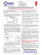
FIGURE A.1 - CONNECTION DIAGRAM ON CONNECTION/INPUT ACCESS DOOR
W / L3
V / L2
U / L1
THE LINCOLN ELECTRIC CO. CLEVELAND, OHIO U.S.A.
XA
S24190
use or service this equipment.
Do not touch electrically live parts.
removed.
Only qualified persons should install,
Do not operate with covers
inspecting or servicing machine.
Disconnect input power before
.
.
.
.
CR1
INPUT SUPPLY CONNECTION DIAGRAM
NOTE: Turn main input power to the machine OFF before performing connection procedure. Failure to
do so will result in damage to the machine.
WARNING

A-4
INSTALLATION
POWER WAVE 455
A-4
VOLTAGE SENSING AT THE
WORKPIECE
A four-pin work piece voltage sense lead connector is
located beneath the output stud cover. The use of a
work piece sense lead is optional for most welding
modes, but may be used if desired.
Sense Lead Kits (K490-10, -25 or -50) are available
for this purpose.
To enable the work piece voltage sensing lead, a
jumper must be removed from the Control PC Board
as follows:
1) Turn the Power Wave 455 power OFF.
2) Remove the front nameplate from the Power Wave
455 by removing the six screws from the name-
plate. Save the screws for re-use.
3) Locate P26, located on the upper right edge of the
Control PC Board. It is a 16 pin connector with
only two wires going into it. Unplug P26. It should
remain attached to the main harness.
4) Install the front nameplate on the Power Wave 455
by replacing the six screws saved in Step 2.
5) Plug a Sense Lead into the Sense Lead
Receptacle. Note: Only the lead marked ‘WORK’
is used. The lead marked ‘ELECT’ can be cut off
and discarded.
6) Connect the WORK sense lead clamp to the piece
being welded.
The Power Wave 455 will now use the external work
piece Sense Lead to sense arc voltage in all welding
modes. If the Sense Lead is enabled but not connect-
ed to the work piece, extremely high welding output
currents may result.
To restore normal work piece sensing (at the output
terminals) reconnect P26 to the Control PC board.
The Sense Lead can then be disconnected.
POWER WAVE / POWER FEED WIRE
FEEDER INTERCONNECTIONS
ELECTRODE & WORK LEADS —
ELECTRODE POSITIVE APPLICATIONS
Most welding applications run with the electrode being
positive (+). For those applications, connect the elec-
trode cable between the wire feeder and the positive
(+) output stud on the power source (located beneath
the spring loaded output cover near the bottom of the
case front).
A work lead must be run from the negative (-) power
source output stud to the work piece. The work piece
connection must be firm and secure, especially if
pulse welding is planned. Excessive voltage drops at
the work piece connection often result in unsatisfacto-
ry pulse welding performance.
ELECTRODE & WORK LEADS —
ELECTRODE NEGATIVE APPLICATIONS
When negative electrode polarity is required, such as
in some Innershield™ applications, install as above,
except reverse the output connections at the power
source (electrode cable to the negative (-) stud, and
work cable to the positive (+) stud).
CONTROL CABLE CONNECTIONS
Connect the control cable between the wire feeder
and power source. The power source wire feeder
connection is located under the spring loaded output
cover, near the bottom of the case front. The control
cable is keyed and polarized, so it can be installed in
only one way.
For neatness and convenience sake, both the elec-
trode and control cables can be routed behind the left
or right strain reliefs (under the spring loaded output
cover), and along the channels formed into the base
of the Power Wave, out the back of the channels, and
then to the wire feeder.

A-5
INSTALLATION
POWER WAVE 455
A-5
POWER FEED CONTROL BOX
MOUNTING
In some installations, it may be desirable to mount the
Wire Feeder control box directly to the front of the
Power Wave power source. (The control box is the
box containing the knobs, switches and displays nec-
essary to control the Power Wave / Power Feed weld-
ing system.) Complete details for separating the con-
trol box from the wire drive are contained in the Power
Feed Instruction Manual. Once separated, mounting
instructions are as follows:
1. Disconnect the input power from the Power Wave.
2. Separate the control box from the wire drive on the
Power Feed wire feeder, and remove the control
panels (see the Power Feed Instruction Manual for
details).
3. Remove the front nameplate from the Power Wave
by removing six screws from the metal nameplate.
Save the screws for re-use.
4. Connect the 6-pin connector that comes out the
back of the control box to the 6-pin receptacle that
is tie-wrapped to the harnessing inside the rectan-
gular opening in the power source. It will be nec-
essary to remove one or two of the wire ties in
order to give enough slack to the power source
connector and leads.
5. Position the control box over the rectangular hole
in the Power Wave case front, being careful not to
pinch any leads between the control box and the
case front. Align the four holes in the back of the
control box with the four threaded mounting holes
in the case front. Secure the control box in place
with four of the screws saved from the previous
step.
6. Reassemble the control box.
The Power Feed Wire Drive can now be connected to
the power source wire feeder connector. This con-
nector is located under the spring loaded output
cover, near the bottom of the case front. The control
cable is keyed and polarized, so it can be installed in
only one way. (To ensure proper electrode voltage
sensing, always connect the Wire Drive to the Power
Source wire feeder connector. Do not connect it to
the optional Output Receptacle which may be present
on the Power Feed Control Box.)

B-1
OPERATION
B-1
POWER WAVE 455
OPERATING INSTRUCTIONS
Read and understand this entire section of operating
instructions before operating the machine.
SAFETY INSTRUCTIONS
ELECTRIC SHOCK can kill.
• Do not touch electrically live parts or
electrodes with your skin or wet cloth-
ing.
• Insulate yourself from the work and ground.
• Always wear dry insulating gloves.
FUMES AND GASES can be
dangerous.
• Keep your head out of fumes.
• Use ventilation or exhaust to remove
fumes from breathing zone.
WELDING SPARKS can cause
fire or explosion.
• Keep flammable material away.
• Do not weld on containers that have held com-
bustibles.
ARC RAYS can burn.
• Wear eye, ear, and body protection.
Observe additional Safety Guidelines
detailed in the beginning of this manual.
WARNING

B-2
OPERATION
B-2
POWER WAVE 455
INPUT POWER
ON
OFF
HIGH TEMPERATURE
MACHINE STATUS
CIRCUIT BREAKER
WIRE FEEDER
POSITIVE OUTPUT
NEGATIVE OUTPUT
3 PHASE INVERTER
INPUT POWER
THREE PHASE
DIRECT CURRENT
GMAW
FCAW
GTAW
OPEN CIRCUIT
VOLTAGE
INPUT VOLTAGE
OUTPUT VOLTAGE
INPUT CURRENT
OUTPUT CURRENT
PROTECTIVE
GROUND
WARNING
GRAPHIC SYMBOLS THAT APPEAR ON
THIS MACHINE OR IN THIS MANUAL
U
0
U
1
U
2
I
1
I
2
SMAW

B-3
OPERATION
B-3
GENERAL DESCRIPTION
The Power Wave 455 is a high performance, digitally
controlled inverter welding power source capable of
complex, high-speed waveform control. Properly
equipped, it can support the GMAW, GMAW-P,
FCAW, SMAW, GTAW and CAC-A processes.
RECOMMENDED PROCESSES AND
EQUIPMENT
RECOMMENDED PROCESSES
The Power Wave can be set up in a number of config-
urations, some requiring optional equipment. Each
machine is factory preprogrammed with multiple weld-
ing procedures, typically including GMAW, GMAW-P,
FCAW, SMAW, GTAW and CAC-A, for a variety of
materials, including mild steel, stainless steel, cored
wires, and aluminum.
RECOMMENDED EQUIPMENT
The Power Wave 455 must be used with the Power
Feed family of wire feeders. These feeders are
required to access and make use of the many of the
welding features contained in the Power Wave 455.
DESIGN FEATURES AND ADVANTAGES
A unique feature of the Power Wave is the ability to
function without any controls, when used with Power
Feed wire feeders. All power source control informa-
tion comes to the Power Wave from a Power Feed
wire feeder.
The following chart lists the power source parameters
that can be changed from the Power Feed wire feed-
er, and gives examples of each. (Optional equipment
may be required to access some of the following para-
meters.)
ADDITIONAL DESIGN FEATURES AND
ADVANTAGES
• Designed to NEMA EW-1, IEC 974-1 and CE
Standards.
• Qualifies for “S” mark on nameplate, which means it
can be used in areas where there is increased risk
of electric shock.
• Multiple process output ranges: 5 - 570 amps.
• Easy access for input connections. Connections
are simple strip and clamp (no lugs required).
• F.A.N. (fan as needed). Cooling fan runs only when
necessary.
• Modular construction for easy servicing.
• Thermostatically protected.
• Electronic over current protection.
• Input over voltage protection.
• Utilizes digital signal processing and microprocessor
control.
• Simple, reliable input voltage change over.
• All system components communicate and transfer
information.
• Auto device recognition simplifies accessory cable
connections.
POWER WAVE 455
Parameter
Welding
Mode
Output
Trim
Arc Control
Examples
Stick Crisp, Stick Soft, Flux Cored with Gas,
Flux Cored without Gas, CV, Synergic CV,
.035 Stainless Pulse, .045 Steel Pulse, 5356
Aluminum Pulse
Current (CC modes), Voltage (CV modes),
Wire Feed Speed (synergic modes)
.500 to 1.500 (only in Pulse modes)
-10.0 to +10.0

B-4
OPERATION
POWER WAVE 455
B-4
WELDING CAPABILITY
The POWER WAVE 455 is rated 400A@ 36V, 100%
duty cycle or 500A@40V 60% duty cycle. The
machine is capable of higher outputs at lower duty
cycles.
If the duty cycle is exceeded, a thermostat will shut off
the output until the machine cools to a reasonable
operating temperature.
LIMITATIONS
• The Power Wave is not recommended for process-
es other than those listed.
• The Power Wave can only be used with Power
Feed wire feeders. Other models of Lincoln feed-
ers, or any models of non-Lincoln wire feeders, can-
not be used.
COMPATIBLE LINCOLN EQUIPMENT
All Lincoln Power Feed™ Wire Feeders.
POWER SOURCE OPERATION
DUTY CYCLE AND TIME PERIOD
The POWER WAVE 455 is rated at 400A@ 36V,
100% duty cycle or 500A@40V 60% duty cycle. The
duty cycle is based upon a ten minute period. A 60%
duty cycle represents 6 minutes of welding and 4 min-
utes of idling in a ten minute period.
CASE FRONT CONTROLS
All operator controls and adjustments are located on
the case front of the Power Wave.
1. POWER SWITCH: Controls input power to the
Power Wave.
2. STATUS LIGHT: A two color light that indicates
system errors. Normal operation is a steady green
light. Error conditions are indicated as follows:
NOTE: The Power Wave 455 status light will flash
green, and sometimes red and green, for up to one
minute when the Power Wave 455 is first turned on.
This is a normal situation as the machine goes
through a self test at power up.
3. HIGH TEMPERATURE LIGHT (thermal overload):
A yellow light that comes on when an over temper-
ature situation occurs. Output is disabled until the
machine cools down. When cool, the light goes
out and output is enabled.
4. 10 AMP WIRE FEEDER CIRCUIT BREAKER:
Protects 40 volt DC wire feeder power supply.
5. 5 AMP AUXILIARY POWER CIRCUIT BREAKER:
Protects 220 volt AC case front receptacle auxiliary
supply.
Light
Condition
Steady Green
Blinking
Green
Alternating
Green and
Red
Steady Red
Blinking Red
Meaning
System OK. Power source communicating nor-
mally with wire feeder and its components.
Nothing connected to Wire Feeder
Receptacle.
Recoverable system fault.See
Troubleshooting Section.
Non-recoverable system fault. Must turn
power source off, find source of error, and
turn power back on to reset. See
Troubleshooting Section.
See Troubleshooting Section.

B-5
OPERATION
B-5
WELDING ADJUSTMENTS
All adjustments are made on the system component
known as the control box, which contains the switch-
es, knobs and digital displays necessary to control
both the Power Wave and a Power Feed wire feeder.
Typically, the control box is supplied as part of the
wire feeder. It can be mounted directly on the wire
feeder itself, or mounted separately, as might be done
in a welding boom installation.
Because the control box can be configured with many
different options, your system may not have all of the
following adjustments. Regardless of availability, all
controls are described below. For further information,
consult the Power Feed wire feeder instruction manual.
1. WFS / AMPS:
In synergic welding modes (synergic CV, pulse
GMAW) WFS (wire feed speed) is the dominant
control parameter, controlling all other variables.
The user adjusts WFS according to factors such as
weld size, penetration requirements, heat input, etc.
The Power Wave then uses the WFS setting to
adjust its output characteristics (output voltage, out-
put current) according to pre-programmed settings
contained in the Power Wave. In non-synergic
modes, the WFS control changes the wire feed
speed according to the desired procedure.
In constant current modes (stick, TIG) this control
adjusts the output current, in amps.
2. VOLTS / TRIM:
In constant voltage modes (synergic CV, standard
CV) the control adjusts the welding voltage.
In pulse synergic welding modes (pulse GMAW
only) the user can change the Trim setting to adjust
the arc length. It is adjustable from 0.500 to 1.500.
A Trim setting of 1.000 is a good starting point for
most conditions.
3. WELDING MODE:
May be selected by name (CV/MIG, CC/Stick Crisp,
Gouge, etc.) or by a mode number (10, 24, 71, etc.)
depending on the control box options. Selecting a
welding mode determines the output characteristics
of the Power Wave power source. For a more
complete description of the welding modes avail-
able in the Power Wave, see the explanation
below.
4. ARC CONTROL:
Also known as Inductance or Wave Control. Allows
operator to vary the arc characteristics from “soft”
to “harsh” in all weld modes. It is adjustable from -
10.0 to +10.0, with a nominal setting of 00.0. (The
nominal setting of 00.0 may be displayed as OFF
on some Power Feed wire feeder control panels.)
See the Welding Mode descriptions, below, for
detailed explanations of how the Arc Control affects
each mode.
DETAILED WELD MODE DESCRIPTIONS
CONSTANT VOLTAGE (CV/WELD, CV/MIG,
CV/FLUX CORED) PROCEDURES
For each wire feed speed, a corresponding voltage is
preprogrammed into the machine through special soft-
wares at the factory. This preprogrammed voltage is
the best average voltage for the procedure at the
given wire feed speed. If the wire feed speed is
changed on the wire feeder, the voltage automatically
changes with it.
In some cases, the operator may want to change the
preprogrammed voltages; for example, to compensate
for cable and fixture voltage drops. The preset volt-
ages can be adjusted on the wire feeder’s Voltage
display. When a change is made to the voltage at
one wire feed speed, this change is applied to all
other wire feed speed settings. For example, if the
operator turns up the voltage by 10 percent, the
machine automatically increases the preset voltages
at all the other wire feed speeds by 10 percent. The
preset voltage, programmed at the factory, may be
changed with the wire feeder VOLTS adjustment.
The Arc Control adjusts the inductance. (This adjust-
ment is often referred to as “pinch”. Inductance is
inversely proportional to pinch.) Increasing the Arc
Control setting decreases the inductance, which
results in the arc getting colder and pinched tighter.
Decreasing the Arc Control setting increases the
inductance, which results in the arc getting wider
(reduced pinch).
GMAW PULSE PROCEDURES
In these procedures, the actual voltage greatly
depends on the waveform used. The peak currents,
background currents, rise times, fall times, and pulse
times all affect the actual voltage. The actual voltage
for a given wire feed speed is not directly predictable
unless the waveform is known. In this case, it is not
practical to preset an actual voltage for the procedure.
Instead, an arc length adjustment is provided. The
machine “knows” what the best arc length is at the
given wire feed speed but allows the operator to
change it.
POWER WAVE 455

B-6
OPERATION
B-6
The arc length trim (usually referred to simply as
“trim”) can be adjusted between 0.500 and 1.500 on
the control box’s Volts/Trim display. A Trim of 1.000
means that no adjustments will be made to the preset
arc lengths. A Trim greater than 1.000 increases the
preset arc lengths. A Trim setting less than 1.000
decreases the preset arc lengths. The arc length trim
adjustment is factored in at all wire feed speed set-
tings. Increasing the Trim by 10 percent at a given
wire feed speed also increases all the other arc length
trim settings of the procedure by 10 percent.
The Power Wave utilizes a control scheme known as
adaptive control in all pulse modes. Because the
Power Wave utilizes adaptive control, it can adjust the
pulsing parameters based on changes in the arc due
to changes in the electrical stickout of the electrode.
(Electrical stickout is the distance from the contact to
to the workpiece.)
The Power Wave is optimized
for use with a 19 mm (.75”) stickout. The adaptive
behavior is programmed to support a stickout range
from 13 mm (.5”) to 32 mm (1.25”). In the low and
high end of the wire feed speed ranges of most
processes, the adaptive behavior may be restricted.
This is a physical restriction due to reaching the edge
of the operating range for the process.
The Arc Control adjustment allows the pulse frequen-
cy to be varied. Increasing the Arc Control causes the
frequency setting to increase, while decreasing the
Arc Control causes the frequency to decrease.
Varying the Arc Control, and hence, the pulse fre-
quency, affects the droplet transfer and allows fine-
tuning for different welding positions.
CONSTANT CURRENT (CC/STICK, CC/TIG)
PROCEDURES
Stick welding can be performed by choosing one of
the stick welding modes. Check the Power Feed wire
feeder Operator’s Manual for instructions on how to
energize the output terminals on the Power Wave.
(Certain options energize the terminals automatically
while other options require a manual adjustment to
energize the terminals.) The output current is set by
the Amps control on the Power Feed wire feeder. The
Volts/Trim adjustment has no effect in this mode.
The Arc Control adjusts the arc force. Increasing the
Arc Control setting increases the arc force, making
the arc more harsh but less likely to stick. Decreasing
the Arc Control setting decreases the arc force, mak-
ing the arc softer and smoother.
ARC GOUGING PROCEDURES
Arc gouging can be performed by choosing the arc
gouging weld mode. Doing so automatically ener-
gizes the output terminals on the Power Wave, mak-
ing the power source immediately ready to weld. The
output current is set by the Amps control on the
Power Weld wire feeder. The Volts/Trim adjustment
has no effect in this mode.
The Arc Control adjusts the arc force. Increasing the
Arc Control setting increases the arc force, making
the arc more harsh but less likely to stick. Decreasing
the Arc Control setting decreases the arc force, mak-
ing the arc softer and smoother.
POWER WAVE 455

C-1
ACCESSORIES
C-1
OPTIONS / ACCESSORIES
FACTORY INSTALLED
There are no factory installed options available for the
Power Wave machines.
FIELD INSTALLED
The following options/accessories are available for
your Power Wave from your local Lincoln Distributor.
K1570-1 Dual Cylinder Undercarriage
K940-10 Voltage Sense Lead Kit- 10 foot voltage
sense lead kit.
K940-25 Voltage Sense Lead Kit- 25 foot voltage
sense lead kit, if additional length is required.
K940-50 Voltage Sense Lead Kit- 50 foot voltage
sense lead kit, if additional length is required.
POWER WAVE 455

D-1
MAINTENANCE
D-1
POWER WAVE 455
SAFETY PRECAUTIONS
ELECTRIC SHOCK can kill.
• Only Qualified personnel should
perform this maintenance.
• Turn the input power OFF at the
disconnect switch or fuse box
before working on this equipment.
• Do not touch electrically hot parts.
ROUTINE MAINTENANCE
Routine maintenance consists of periodically
blowing out the machine, using a low pressure
airstream, to remove accumulated dust and dirt
from the intake and outlet louvers, and the cooling
channels in the machine.
WARNING

E-1
TROUBLESHOOTING
E-1
POWER WAVE 455
USING THE STATUS LED TO
TROUBLESHOOT SYSTEM PROBLEMS
The Status LED on the power source case front
can help diagnose problems down to the system
component (power source, wire feeder, wire drive,
etc.) level. If, for any reason, the system does not
appear to be working properly, always check the
color of the Status LED, and refer to the following
chart to help you determine which system compo-
nent (power source, wire feeder, wire drive, etc.)
may be faulty. Replace the components identified
as potentially faulty with known good compo-
nents, and the system should operate normally.
Status LED is solid green (no blinking).
Status LED is blinking green.
Status LED is solid red (no blinking).
Status LED is blinking red and green.
Status LED is blinking red.
System operating normally.
1. Normal condition for the first few seconds after the
power is turned on.
2. Wire feeder and/or its components are not prop-
erly configured and/or connected together. Refer
to wire feeder instruction manual(s) for wire feeder
configuration information.
1. Indicates that nothing is connected to the Wire
Feeder Receptacle. Connect a Power Feed Wire
Feeder to the wire feeder receptacle.
2. Power source cannot communicate with the wire
feeder and/or its components due to a problem
within the power source. Contact an authorized
Lincoln Electric Service facility.
1. If the Thermal LED is also lit, see “Yellow Thermal
LED Lit” in the Main Troubleshooting Chart.
2. Input voltage is too high or too low. Make certain
that input voltage is proper, according to the
Rating Plate located on the rear of the machine.
3. Power source is having trouble communicating
with wire feeder or its components. Turn machine
off. Disconnect control cable from the Wire
Feeder Receptacle. Turn power back on. If
Status LED then blinks green, the problem is with
the wire feeder. If light is still blinking red and
green, contact an authorized Lincoln Field Service
facility.
1. Error code display. Contact an authroized Lincoln
Field Service Shop.
/