Page is loading ...

UNINTERRUPTIBLE POWER SUPPLY (UPS) + LIGHTING FLOW DIMMER STABILIZERS (ILUEST) + SWITCH MODE POWER SUPPLY + STATIC INVERTERS + PHOTOVOLTAIC INVERTERS + VOLTAGE STABILIZERS AND POWER LINE CONDITIONERS
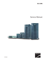
UPS SLC TWIN PRO series
0.7 to 3 kVA
USER’S MANUAL
UNINTERRUPTIBLE POWER SUPPLY


3
SALICRU
General index
1. Introduction.
1.1. Acknowledgement letter.
1.2. Using this manual.
1.2.1. Conventions and used symbols.
1.2.2. For more information and/or help.
1.2.3. Safety instructions.
1.2.3.1. General safety warnings.
1.2.3.2. To keep in mind.
1.2.3.3. Safety warning regarding batteries.
2. Quality and standard guarantee.
2.1. Declaration of the management.
2.2. Standard.
2.3. Environment.
3. Presentation.
3.1. Views.
3.1.1. Views of the equipment.
3.2. Definition of the product.
3.2.1. Nomenclature.
3.3. Operating principle.
3.3.1. Main features.
3.4. Options.
3.4.1. Isolation transformer.
3.4.2. External maintenance manual bypass.
3.4.3. Integration in IT networks by means of the SNMP adaptor.
3.4.4. Relays interface card.
3.4.5. MODBUS protocol.
4. Installation.
4.1. To be considered in the installation.
4.2. Reception of the equipment.
4.2.1. Unpacking, content checking and inspection.
4.2.2. Storage.
4.2.3. Unpacking.
4.2.4. Transport to location.
4.3. Connection.
4.3.1. Connection of input .
4.3.2. Connection to output.
4.3.3. Connection of external batteries (extended back up times) -B1-.
4.3.4. Connection of main input earth terminal ( ) and the earth bonding
terminal ( ).
4.3.5. Terminals for EPO (Emergency Power Off).
4.3.6. Communication ports.
4.3.6.1. USB interface.
4.3.6.2. Protection against transient voltages for Modem / ADSL / Fax / ...
lines.
4.3.6.3. Smart slot.
4.3.6.4. Relays interface (option).
4.3.7. Software.
4.3.8. Considerations before starting up the connected loads.
5. Operating.
5.1. UPS commissioning and shutdown.
5.1.1. Preliminary controls.
5.1.2. Start up the UPS, with AC mains.
5.1.3. Start up the UPS, with no AC mains (Battery mode)
5.1.4. UPS shutdown with AC mains (on Inverter mode).
5.1.5. UPS shutdown with no AC mains (on Battery mode).
5.1.6. Battery test function.
5.1.7. Alarm silencer.
5.1.8. EPO (Emergency Power Output).
6. Control panel with LCD.
6.1. Control panel.
6.2. Setting and configuration of the control panel.
6.2.1. No output mode, code «0».
6.2.2. Bypass mode, code «1».
6.2.3. Line mode.
6.2.4. Battery mode / Battery test mode.
6.2.5. Wrong mode.
6.2.6. ECO mode (Economy).
6.2.7. Converter mode.
6.3. Settings through the LCD panel of the synoptic.
7. Maintenance, warranty and service.
7.1. Battery maintenance.
7.1.1. Notes for installing and replacing the batteries.
7.2. UPS Trouble Shooting guide.
7.2.1. Troubleshooting guide. Warning indications.
7.3. Warranty conditions.
7.3.1. Covered product.
7.3.2. Warranty terms.
7.3.3. Out of scope of supply.
7.4. Description of the available maintenance and service
contracts.
7.5. Technical service network.
8. Annexes.
8.1. General technical specifications.
8.2. Glossary.

4
SALICRU
1. Introduction.
1.1. Acknowledgement letter.
We would like to thank you in advance for the trust you have
placed in us by purchasing this product. Read this instruction
manual carefully before starting up the equipment and keep it for
any possible future consult that can arise.
We remain at you entire disposal for any further information or
any query you should wish to make.
Yours sincerely.
The equipment here described can cause important
physical damages due to wrong handling. This is
why, the installation, maintenance and/or fixing of the
here described equipment must be done by our staff or
specifically authorised.
According to our policy of constant evolution, we reserve
the right to modify the specifications in part or in
whole without forewarning.
All reproduction or third party concession of this
manual is prohibited without the previous written au-
thorization of our firm.
1.2. Using this manual.
The target of this manual or publication is to provide information
regarding the safety and to give explanations about the proce-
dures for the installation and operating of the equipment. This
manual and rest of support documentation has to be read care-
fully before installing, location change, setting or any handling of
any kind, including the start up and shutdown operation.
Keep this document for future consults.
In the next pages, the “equipment” and “S.T.S.” terms, are re-
ferred to the Uninterruptible Power Supply or UPS and Service
and Technical Support respectively.
1.2.1. Conventions and used symbols.
Some or all the symbols of this section can be used and shown
in the equipment and/or in the description of this document. It is
advisable to be familiar with them and understand their meaning.
• «Danger of electrical discharge» symbol. Pay spe-
cial attention to it, both in the indication on the equip-
ment and in the paragraph referred to this user’s manual,
because it contents features and basic informations for
person safety. To not respect these indications can result in
serious incidents or even the death due to electrical dis-
charges
• «Warning» symbol. Carefully read the indicated par-
agraph and take the stated prevention measures, so it
contents basic safety instructions for persons. To not respect
such instructions can cause serious incidents. Those indica-
tions with “CAUTION ” symbol content features and basic in-
structions for safety of the things. To not respect such
instructions can damage the goods.
• «Precaution» symbol. Read the paragraph text and
take the stated preventive mediums, it contents the
basic instructions and features for the equipment safety. To
not respect these indications can create material damages
on the own equipment, installation or loads.
• «Notes of information» symbol. Additional topics that
complement the basic procedures. These instructions
are important for the equipment use and its optimum
efficiency.
• «Main protective earthing terminal» symbol. Con-
nect the earth cable coming from the installation to this
terminal.
• «Earth bonding terminal». Connect the earth cable
coming from the load and the external battery cabinet to
this terminal.
• Preservation of the environment: The presence of
this symbol in the product or in their associated docu-
mentation states that, when its useful life is expired, it
will not be disposed together with the domestic residuals. In
order to avoid possible damages to the environment, sepa-
rate this product from other residuals and recycle it suitably.
The users can contact with their provider or with the pertinent
local authorities to be informed on how and where they can
take the product to be recycled and/or disposed correctly.
• Alternating Current A.C..
• Direct Current D.C..
• Recycle.
1.2.2. For more information and/or help.
For more information and/or help of your specific unit, contact
with our Service and Technical Support (S.T.S.).
1.2.3. Safety instructions.
• Check the data of the nameplate are the required by the in-
stallation.
• Never forget that the UPS is a generator of elec-
trical energy, therefore the user has to take precau-
tions about against direct and indirect contacts.
Its energy source, a part from the AC mains, lies on the bat-
teries, usually included in the same case or cabinet that the
equipment electronics. However, some models and/or ex-
tended back up times, batteries can be supplied in a separate
case or cabinet.
If the batteries are connected to the equipment and their pro-
tections are switched “On”, whenever they are, it is irrelevant
if the UPS is or not connected to mains, as well as the status
of the mains protection. The outlets or output power blocks
will supply voltage meanwhile the battery set has energy.
• Compliance as regards to “Safety instructions“ is
mandatory, being the user the legal responsible
regarding to its observance and application. Read them care-
fully and follow the stated steps in the established order, keep
them for future consults that may arise.
• If the instructions are not in total or partial and in
special referred to the safety, do not carry on with
the installation or commissioning tasks, because there
USER MANUAL

5
SALICRU
could be a risk on your safety or on the other/s persons,
being able to make serious injuries even the death, also it
can cause damages to the equipment and/or to the loads
and installation.
• The local electrical regulations and the different re-
strictions of the client’s site, they can invalidate some
recommendations included in the manuals. When discrepan-
cies exist, the user has to comply the local regulations.
• The equipments provided with power cord with plug
and outlets, can be connected and used by personnel
without any kind of experience.
The equipments with power blocks have to be installed by
qualified personnel and it can be used by personnel with
not specific training, just with only help of this manual.
A person is defined as qualified, if it has experience of as-
sembling, commissioning and perfect control operating of
the equipment, if he has the requirements to do the job and
if has read and understand all the things described in this
manual, in particular the safety indications. Such preparation
is considered only valid if it is certified by our S.T.S..
• Place the equipment the closest to the power supply and
loads to be supplied, leaving an easy access if it were needed
an urgent disconnection.
In the hard wired equipments and due to the impossibility of
fast disconnection, a diconnection device (switch) with easy
access and close to the equipment will be installed.
• Warning labels should be placed on all primary power
switches installed in places away from the equipment to alert
the electrical maintenance personnel of the presence of a
UPS in the circuit
The label will bear the following text or an equivalent one:
Before working in this circuit.
• Isolate the Uninterruptible Power System (UPS).
• Check the voltage between all terminals including the
protective earth.
Risk of voltage feedback from UPS.
1.2.3.1. General safety warnings.
• All connections and disconnections of the cables from the
equipment, including the control ones, will be done with no
power supply and the switches on rest, position «O» or «Off».
• Shutdown the equipment completely by switching «Off» the
button of the control panel first. Next disconnect the cable
from the wall outlet for equipments up to standard 3 kVA or by
switching «Off» the input circuit breaker of the installation and
disconnect the power supply cables in models of the 3 kVA B1
or higher power rate.
The indiscriminate manoeuvring of the switches may
involve production losses and/or equipment dam-
ages. Consult the documentation before doing any action
• Pay special attention to the labelling of the equipment
that warns about the «Electrical shock hazard». Inside
the equipment there are dangerous voltages, never open the
enclosure, the access has to be done by qualified staff. In
case of maintenance or fault, consult to the closest (S.T.S.).
• Cross cable sections used to supply the equipment and loads,
will be according to the nominal current stated in the nameplate
label of the equipment, and respecting the Low Voltage Electro-
technical Regulations or standards of the country.
Use approved cables only
• Protection Earth cable of the UPS drives the leakage
current of the load devices. An isolated earth cable has
to be installed as part of the circuit that supplies the equip-
ment. Cross cable section and its features will be same as
the power supply cables, but with green colour with or without
the yellow strip.
All outlets of the UPS has an earth bonding, duly connected
and those equipments with power blocks there is an exclusive
terminal for the load earth connection. When an outgoing dis-
tribution is done, i.e power strips, it is essential that they have
an earth terminal connected to each one of them.
It is essential that the cables that supplies the loads have the
earth connection cable.
The protection earth must be connected to the frame
or metallic chassis of any electrical equipment (in our
case to the UPS, battery cabinet or case and loads), assuring
that it is done before connecting the input voltage.
Check the quality and availability of the earth, it has to be
between the defined parameters by the local or national
regulations.
• For the smallest devices (the ones connected with the fore-
seen power cord with plug), the user has to check the wall
outlet corresponds with the type of supplied plug, with earth
duly installed and connected to the local protection earth.
• During the normal UPS operation, in equipments up to
3kVA the power cord cable can’t be disconnected
from wall outlet, because the protection earth of the own UPS
would be disconnected and also the earth from the loads
connected to the output.
For this reason, the general protection earth cable of the
building or switchgear panel that supplies the UPS will not
be disconnected.
• In small equipments (the ones connected with the foreseen
power cord with plug), check that the sum of the leakage currents
of the UPS and connected load/s do not exceed over 3,5mA.
• The installation will have input protections sized to the cur-
rents of the equipment and stated in the nameplate label
(RCD devices type B and circuit breakers with C character-
istic or any other equivalent one).
Overload conditions are considered as a nonpermanent an
exceptional operating mode, so these currents will not be
kept in mind when sizing the protections.
• Do not overload the UPS by connecting loads with inrush
consumptions at its output, like laser printers.
• Output protection will be done with a circuit breaker of C char-
acteristic or an equivalent one.
It is recommended to distribute the output power, into four
lines as minimum. Each one of them will have a protection
circuit breaker sized to the quarter of the nominal power.
This kind of outgoing distributions will allow that any fault in
any device connected to the equipment, that makes a short-
circuit, will affect to the line with the faulty device only. An
uninterruptible power supply will be guaranteed to the rest of
connected loads, due to the protection tripping of the affected
line by the short-circuit only.
• When replacing a fuse, do it for another of the same type, char-
acteristics format and size.
• Under any concept the input power cord will be connected to the
output of the equipment, either directly or through other ways.
• All the equipments have an auxiliary terminal strip to install
an external emergency power off button (EPO), and it will be-
long to the user property.
Type of circuit is selectable through the LCD panel of the
equipment. The contact is preset from factory as normally

6
open, so the button must be switched to close the circuit and
the voltage to the loads is broken. To establish the power
supply to the loads again, the EPO button must be deacti-
vated.
EPO doesn’t affect to the power supply of the equipment, it
only breaks the power supply to the loads as a safety measure.
• When supplying input voltage to a UPS with static by-
pass, although the inverter is still turned «Off» (deac-
tivated) it doesn’t mean that at the output there will not be
voltage.
So, to do it, the input switch will have to be turned «Off».
Put warnings of danger and/or emergency switches if the
safety Standards require it in your particular installation.
• All power supply electrical cables have to be fixed to the
equipments and loads, interfaces, etc..., to unmovable parts
and in the way to avoid treads, trips on them or fortuitous
pulls.
• CHASSIS or RACK mounted equipments are destined to be in-
stalled in a predetermined set to be done by professionals.
The installation has to be designed and executed by qual-
ified personnel, who will be the responsible to apply the
safety and EMC regulations and standards that controls
the particular installations where the product is destined.
The equipments assembled in CHASSIS do not have
enclosure protection, even the power blocks are unpro-
tected.
Some RACK mounted equipments do not have the power
blocks protected.
• Never manipulate the equipment with wet hands.
1.2.3.2. To keep in mind.
• Do not try to dismantle or change any part of the
equipment, if this action is not contemplated in this
document. Manipulation inside the UPS due to any modifica-
tion, reparation or any other cause, can make an electrical
discharge of high voltage and it is restricted to qualified staff
only. Do not open the equipment.
A part from the implicit stated risks, any action that make the
modification, internal or external of the equipment or just only
the simple intervention inside of itself, which is not stated in
this document, it can expire the warranty.
• If it is observed that the UPS exhausts smoke or toxic gas,
shutdown it immediately and disconnect it from the power
supply. This kind of fault can cause fire or electrical dis-
charge. Contact with our (S.T.S.).
• In case of an accidental equipment dropping or if the enclo-
sure is damaged, do not start it up under any concept. This
kind of fault can cause fire or electrical discharge. Contact
with our (S.T.S.).
• Do not cut, manipulate the electrical cables, do not put heavy
objects over them too. Any of these actions could cause a
short-circuit and make a fire or electrical discharge.
Check that the electrical cables of connection, plugs and out-
lets are in good conditions.
• When moving an equipment from a cold place to a warm en-
vironment and vice versa, it can cause condensation (small
water drops) in the external and internal surfaces. Before in-
stalling a moved equipment from another place or even pack-
aged, the equipment will be left for a minimum time of two
hours in the new location before making any action, with the
purpose of adapting it to the new environmental conditions
and avoid the possible condensations.
The UPS has to be completely dry before starting any instal-
lation task.
• Do not store, install or expose the equipment in corrosive,
wets, dusty inflammable or explosive environments and
never outdoors.
• Avoid to locate, install or store the equipment in a place with
direct sunlight or high temperatures. Batteries could be dam-
aged.
In the exceptional case and long exposition to intense heat,
batteries can cause filtrations, overheating or explosions,
which can cause fires, burn or other injuries. High tempera-
tures can also make deformation in the plastic enclosure.
• The location will be spacious, airy, away from heat sources
and easy access.
• Do not obstruct the cooling grids by entering objects through
themselves or other orifices.
• In equipments of low power rate (up to 3kVA), leave as min-
imum space of 25 cm in the equipment peripheral and 50 cm
for higher power rates equipments.
• Also in the UPS with power blocks, it is recommended to
leave another additional 50 cm for an eventual intervention
of the (S.T.S.), considering that if it means to move the UPS,
the connected cables will have the needed clearance.
• Do not put materials over the equipment or parts that obstruct
the correct visualization of the synoptic.
• Be careful to not wet it, because it is not waterproof. Do not
allow entering any kind of liquids in. If accidentally the outside
of the machine comes into contact with liquids or salt air, dry
it with a soft and absorbent cloth.
• To clean the equipment, wipe over a damp cloth and then
dry it. Avoid sprinkling or spillage that could enter through the
slots or cooling grids, which may cause fire or electric shock.
Do not clean the equipments with products that could have
alcohol, benzene, solvent or other inflammable substances,
or they are abrasive, corrosive, liquids or detergent.
• When it is needed to remove the protection cover to access
to the terminals, they will have to be put back before starting
up the equipment. Otherwise you may incur personal injury
or equipment damage.
• Be careful to not lift heavy loads without help, according to
the following recommendations:
, < 18 kg.
, 18 - 32 kg.
, 32 - 55 kg.
, > 55 kg.
• UPSs are electronic equipments, so they will be treated as
they are:
Avoid shocks.
Avoid jolting or bouncing of the UPS, like those produced
by moving the equipment on a hand truck and move on
an uneven or wavy surface.
• UPS transport will be done packaged inside its original pack-
aging in order to prevent it from shock and impact and by
means of the suitable type of packaging (carton box, pallet
packaging, ...) and appropriate to its weight.
• Although the physical location of the elements can differ from
the illustrations in this manual in some cases, the correct la-
belling correct the possible doubts and makes easy its com-
prehension.
USER MANUAL

7
SALICRU
1.2.3.3. Safety warning regarding batteries.
• The manipulation and connection of the batteries
shall be done and supervised by personnel with
battery knowledge only.
Before doing any action, disconnect the batteries. Check that
no current is present and there is not dangerous voltage in
the DC BUS (capacitors) or in the endpoint of the battery set
terminals.
Battery circuit is not isolated from input voltage. Dangerous
voltages can be found between the terminals of the battery
set and the earth. Check that there is not any voltage at the
input before take any action over them.
• When faulty batteries are replaced, the complete battery set
has to be replaced, less exceptional cases in new equip-
ments, were due to manufacturing faults it will only be re-
placed the defective ones.
The replacement will be done by another one of the same
type, voltage, capacity, quantity and brand. All of them has to
be of the same brand.
• Generally, the used batteries are sealed lead acid of 12V and
maintenance free (VRLA).
• Do not reuse the faulty batteries. There could be an explo-
sion or burst any battery with the involved problems and is-
sues that could happen.
• Generally supplied batteries are installed in the same cab-
inet, case or rack of the equipment. Depending on the power,
autonomy or both, they can be supplied separately from the
equipment in another cabinet, case or rack, with the interlink
cables among them. Do not modify its length.
• In those equipments requested without batteries, their ac-
quisition, installation and connection of themselves will be
done by the end-user and under his responsibility. Data
concerning the batteries as regards to quantity, capacity and
voltage, are stated in this battery label sticked beside the
nameplate of the equipment. Respect these data, battery
connection polarity and the supplied circuit diagram strictly.
For an optimum and efficient operating, the battery set has to
be located as close as possible to the equipment.
• The battery voltage can involve the risk of electric
shock and can produce high short circuit currents. Ob-
serve the following preventive measures before manipulating
any terminal block identified in the labelling as «Batteries»:
Disconnect the corresponding protection elements.
When connecting a battery cabinet to the equipment,
respect the cable’s polarity and colour (red-positive;
black-negative) indicated in the manual and in the cor-
responding labelling.
Wear rubber gloves and shoes.
Use tools with insulated handles.
Take off watches, rings or other metal objects.
Do not place metal tools or objects over the batteries.
Never manipulate with your hands or through conducting
objects, do not short either the battery terminal block of
the equipment or the own from the batteries.
• In order to avoid a complete discharge of the batteries and
as a safety measure after a long blackout of the commercial
mains and when ending the working day, proceed to the load
shutdown and then to the equipment too, by following the op-
erating described in this «User’s manual».
• When the equipment and/or battery module has a protec-
tion through a fuse and it were needed to be replaced, it will
always be done by another one with the same dimension,
type and size.
• For long periods of disconnection, consider that the equip-
ment has to be connected once a month for 10 hours as
minimum, in order to charge the batteries, so the irreversible
degradation of itself is avoided. On the other hand, in case of
storing an equipment, it will be done in a fresh and dry place,
never outdoors.
• Never short the battery terminals as it involves a high risk. It
involves the detriment of the equipment and batteries.
• Avoid mechanical efforts and impacts.
• Do not open or mutilate the battery. Spilled electrolyte is
harmful and toxic to the skin and eyes.
• Do not dispose the batteries in a fire and high temperatures.
The batteries may explode.
• In case of contact of the acid with parts of the body, wash
immediately with plenty water and call urgently the nearest
medical service.
• Batteries involve a serious risk for the health and for the en-
vironment. Their disposal should be done according to the
existing laws.

8
2. Quality and standard
guarantee.
2.1. Declaration of the management.
Our target is the client’s satisfaction, therefore this Management
has decided to establish a Quality and Environmental policy, by
means of installation a Quality and Environmental Management
System that becomes us capable to comply the requirements
demanded by the standard ISO 9001 and ISO 14001 and by our
Clients and concerned parts too.
Likewise, the enterprise Management is committed with the de-
velopment and improvement of the Quality and Environmental
Management System, through:
• The communication to all the company about the impor-
tance of satisfaction both in the client’s requirements and in
the legal and regulations.
• The Quality and Environmental Policy diffusion and the fixa-
tion of the Quality and Environment targets.
• To carry out revisions by the Management.
• To provide the needed resources.
2.2. Standard.
The SLC TWIN PRO product is designed, manufactured and
commercialized in accordance with the standard EN ISO 9001
of Quality Management Systems. The marking shows the
conformity to the EEC Directive by means of the application of
the following standards:
• 2006/95/EC Low voltage directive.
• 2004/108/EC Electromagnetic Compatibility directive
(EMC).
In accordance with the specifications of the harmonized stand-
ards. Standards as reference:
• EN-IEC 62040-1. Uninterruptible power supply (UPS). Part
1-1: General and safety requirements for UPS’s used in ac-
cessible areas by end users..
• EN-IEC 60950-1. IT equipments. Safety. Part 1: General re-
quirements.
• EN-IEC 62040-2. Uninterruptible power supply (UPS). Part
2: EMC requirements.
The manufacturers responsibility is excluded in the event
of any modification or intervention in the product by the
customer’s side.
This is a product for its use in commercial and industrial
applications, so restrictions and additional measures can
be needed in the installation to prevent perturbations.
Declaration of conformity CE of the product is at the client
disposal under previous request to our headquarters offices.
2.3. Environment.
This product has been designed to respect the environment
and has been manufactured in accordance with the standard
ISO 14001.
Equipment recycling at the end of its useful life:
Our company commits to use the services of authorised socie-
ties and according to the regulations, in order to treat the recov-
ered product at the end of its useful life (contact your distributor).
Packaging:
To recycle the packing, follow the legal regulations in force.
Batteries:
The batteries mean a serious danger for health and environ-
ment. The disposal of them must be done in accordance with
the standards in force.
USER MANUAL

9
SALICRU
3. Presentation.
3.1. Views.
3.1.1. Views of the equipment.
Figures 1 to 3 show the illustrations of the equipment according
to the case format and depending on the power of the model.
Nevertheless and due to the constant evolution of the product,
some discrepancies or small contradictions can arise. In front
of any doubt, the labelling of the equipment will always prevail.
Figures regarding its main features or specifications can
be checked in the nameplate of the equipment. Keep them
in mind for its installation.
Models from 0.7 and 1 kVA Models from 1.5 to 3 kVA
Fig. 1. Front view from 0.7 to 3 kVA models.

10
Protection
cover for
smart slot
Output
sockets
Input socket
Input
breaker
protection
Fan
USB
Transient
protection
(*)
EPO
Extended
autonomy
connector
Protection
cover for
smart slot
Output
sockets
Input socket
Input
breaker
protection
Fan
USB
Transient
protection
(*)
EPO
(*) Transient protection (fax, modem,...)
Models from 0.7 and 1 kVA (standard) Models from 0.7 and 1 kVA (B1)
Fig. 2. Rear view from 0.7 and 1 kVA.
Protection cover for
smart slot
Output
sockets
Input socket
Input
breaker
protection
Fans
USB
Transient protection (*)
EPO
Models from 1.5 and 2 kVA (standard) Models from 1.5 and 2 kVA (B1)
(*) Transient protection (fax, modem,...)
Extended
autonomy
connector
Output
sockets
Input socket
Input
breaker
protection
Fans
USB
Transient protection (*)
EPO
Protection cover for
smart slot
Fig. 3. Rear view from 1.5 and 2 kVA.
USER MANUAL

11
SALICRU
Model from 3 kVA (standard) Model from 3 kVA (B1)
(*) Transient protection (fax, modem,...)
Output
sockets
Input socket
Input
breaker
protection
Fans
USB
Transient protection (*)
EPO
Output
terminals
Protection cover for
smart slot
Extended
autonomy
connector
Output
sockets
Input
terminals
Input
breaker
protection
Fans
USB
Transient protection (*)
EPO
Output
terminals
Protection cover for
smart slot
Fig. 4. Rear view from 3 kVA model.

12
Battery module for models 0.7 and 1 kVA Battery module for models 1.5 from 3 kVA
Fig. 5. Front view from battery module.
Battery module for models 0.7 and 1 kVA Battery module for models 1.5 from 3 kVA
Connector
for
connection
to another
module
Connector
for UPS
(extended
autonomy)
Earthing
screw
connection
Connector
for
connection
to another
module
Connector
for UPS
(extended
autonomy)
Earthing
screw
connection
Fig. 6. Rear view battery module for extended
autonomy.
USER MANUAL

13
SALICRU
3.2. Definition of the product.
3. 2.1. Nomenclature.
SLC-2000-TWIN PRO (B1) WCO “EE29503”
MOD BAT TWIN PRO 2x6AB003 40A WCO “EE29503”
EE* Special specifications of the client.
CO “Made in Spain” marking in the UPS and its packaging
(custom issue).
W Neutral brand equipment.
(B0) No batteries and no space for installing them.
(B1) Equipment with extra charger and external batteries to the UPS.
TWIN PRO Series.
2000 Power in VA.
SLC Acronym of the brand.
EE* Special specifications of the client.
CO “Made in Spain” marking in the UPS and packaging
(custom issue).
W Neutral brans of the equipment.
40A Size of the protection.
003 Last three characters of the battery code.
AB Initials of the battery family.
6 Quantity of batteries in one string.
2x Quantity of strings in parallel. Omit for only one.
0/ Battery module without them, but with the accessories
to install them.
TWIN PRO Series of the battery module.
MOD BAT Battery module.
Note as regards to the batteries:
Acronyms B0 and B1 stated in the nomenclature is re-
lated to the batteries:
(B0) The equipment is supplied without the batteries and
with no accessories (screws and electrical cables).
Batteries owned by the client will be installed out
from the case or cabinet of the UPS.
Under request, it is possible to supply the acces-
sories (screws and electrical cables), needed to
install and connect the external batteries.
(B1) Equipment with extra battery charger. The equip-
ment is supplied without batteries and no accesso-
ries (screws and electrical cables), corresponding
to the specific batteries in the model.
Under request is possible to supply the acces-
sories (screws and electrical cables), needed to
install and connect the batteries.
For equipments requested with no batteries, the acquisi-
tion and connection of them will always be done by the
customer and under his responsibility.
Data related to batteries about quantity, capacity and
voltage are stated in the battery label sticked beside the
nameplate of the equipment, respect strictly these data
and connection polarity of the batteries.

14
3.3. Operating principle.
This manual describes the installation and operating of the Un-
interruptible Power Supply (UPS) from SLC TWIN PRO series
as equipments that can run as a complete separate and inde-
pendent units. UPSs from SLC TWIN PRO series assures an
optimal protection for any critical load, keeping the power supply
of the loads between the stated parameters, with no break,
during any blackout, or mains fluctuations or deteriorations with
a wide range of available models (from 0.7 kVA to 3 kVA), it al-
lows adapting the model to the end-user needs.
Thanks to the used technology, PWM (Pulse Width Modulation)
and double conversion, the UPSs from SLC TWIN PRO series
are compact, silent, and with high efficiency.
The double conversion principle cancels all the AC mains per-
turbations. A rectifier converts the alternating current from AC
input mains into DC direct current, that keeps at the optimal level
the batteries and supplies the inverter, which at the same time
generates an AC voltage ready to feed the loads permanently. In
case of fault of the input power supply of the UPS, the batteries
supplies clean energy to the inverter.
The UPS design and construction from SLC TWIN PRO series
have been done in accordance with the international norms.
So, this series has been designed to maximize the availability of
the critical loads and make sure that your business is protected
against fluctuations of voltage, frequency, electrical noises,
blackouts and mains faults, which are present in the energy
distribution lines. This is the main target of the UPSs from SLC
TWIN PRO series.
This manual is applicable to the standardized models and stated
in table 1.
3.3.1. Main features.
• True on-line double conversion and independent output fre-
quency from mains.
• Output power factor of 0,8 and pure sinewave, suitable for
almost any kind of loads.
• Input power factor > 0,99.
• Great adaptability to the worst conditions of the input mains.
Wide margins of the input voltage, frequency range and
wave shape, so it is avoided the excessive dependence on
the limited energy of the battery.
• Availability of battery chargers up to 8 A in order to decrease
the battery recharging time.
• High efficiency mode can be selected > 0,94 (ECO-MODE).
Energy saving, which reverts to the user in an economy way.
• It is possible to start up the equipment without mains or the bat-
tery discharged. Watch this last aspect, because the back up
time will be decreased as much discharged the batteries are.
• The technology of the smart management of the battery is
very useful for making longer the accumulator lifetime and to
optimise the recharging time.
• Standard communications options by means of USB port.
• Control of the remote emergency power off (EPO).
• Control signal of the remote emergency power off (EPO).
• Interface between the user and the equipment through the
control panel LCD, user friendly.
• Option cards are available to improve the communication ca-
pacity of connectivity.
• Easy firmware updating, no need to call to the Service and
Technical Support (S.T.S.).
• Simplified maintenance, which allows replacing the batteries
in a safety way without shutdown the UPS.
Model Power (VA) Type
SLC-700-TWIN PRO 700
Standard
SLC-1000-TWIN PRO 1000
SLC-1500-TWIN PRO 1500
SLC-2000-TWIN PRO 2000
SLC-3000-TWIN PRO 3000
SLC-700-TWIN PRO B1 700
Standard with
extended autonomy
SLC-1000-TWIN PRO B1 1000
SLC-1500-TWIN PRO B1 1500
SLC-2000-TWIN PRO B1 2000
SLC-3000-TWIN PRO B1 3000
Table 1. Standardized basic models.
3.4. Options.
Depending on the selected configuration, the equipment can in-
clude any of the following options:
3.4.1. Isolation transformer.
The isolation transformer, provides a galvanic isolation that al-
lows isolating the output from the input completely.
The installation of an electrostatic shield between the primary
and secondary windings of the transformer provides a high level
of attenuation of the electrical noises.
The isolation transformer can be installed at the input or output
of the UPS from SLC TWIN PRO series and it will always be
located out from the equipment enclosure.
3.4.2. External maintenance manual
bypass.
The purpose of this option is to isolate electrically the equip-
ment from mains and critical loads, without breaking the power
supply to the loads. Therefore, in this way the maintenance or
fixing tasks can be done in the equipment with no interruption on
the power supply energy to the protected system, at the same
time that unnecessary risks are avoided to the technical staff,
because it allows a complete disconnection of the UPS from the
installation.
3.4.3. Integration in IT networks by
means of the SNMP adaptor.
The big IT systems based on LANs and WANs that integrate
servers with different platforms, they have to include an easy
way of controlling and management at the manager system dis-
posal. This facility is got through the SNMP adaptor, which is
well-known by the main software and hardware manufacturers.
USER MANUAL

15
SALICRU
The available SNMP option for SLC TWIN PRO series is a card
to be inserted into the slot that the UPS has in its rear side.
The connection of the UPS with the SNMP is internal meanwhile
the connection between the SNMP and the IT network is done
through a RJ45 connector 10 base.
3.4.4. Relays interface card.
See section 4.3.6.4..
3.4.5. MODBUS protocol.
The big IT systems based on LANs and WANs, many times
they require that the communication with any device to be inte-
grated in the IT network has to be done by means of an industrial
standard protocol.
One of the most used industrial standard protocols in the market
is the MODBUS protocol. SLC TWIN PRO series is also ready
to be integrated in this type of environments through the external
“SNMP TH card” device with MODBUS protocol.

16
4. Installation.
• Check the Safety instructions, from section 1.2.3.
• Check that the data in the nameplate are the required by the
installation.
• A wrong connection or manoeuvring, can make faults in the
UPS and/or loads connected to itself. Read carefully the in-
structions of this manual and follow the stated steps in the
established order.
• The equipments can be installed and used by per-
sonnel with no specific training just with the help of this
«Manual» only, less those ones that are hard wired, which
have to be installed by qualified personnel.
• All connections of the equipment including the control
(interface, remote panel, ...), will be done with the
switches at rest and no voltage present (UPS power supply
switch to «Off»).
• Never forget that the UPS is an electrical energy gener-
ator, so the user has to take the needed cautions against
direct and indirect contacts.
• Battery circuit is not isolated from input voltage. Haz-
ardous voltages can be found out between the battery
terminals and earth. Check that there is not input voltage be-
fore doing any intervention on them.
4.1. To be considered in the
installation.
• All the equipments have power cord with schuko plug to be
connected to the AC mains, less the B1 version of 3 kVA,
which is hard wired.
In the same way, 2 or 3 schuko outlets are supplied depending
on the model, for its connection with the loads (output) and
also to the terminals in all the 3kVA units.
For the rest of connections is used an Anderson connector
for the battery connection (B1 version) and ports for com-
munications.
• Cross cable section of the input and output lines, will be cal-
culated from the currents stated in the nameplate of each
equipment, and respecting the Local and/or National Low
Voltage Electrotechnical Regulations.
• Protections of the switchgear panel, will have the following
features:
For input line, type B for RCD devices and C character-
istic for circuit breakers.
For the output (load feeding), C characteristic for circuit
breaker.
Regarding the size, they will be as minimum to the currents
stated in the nameplate of each UPS.
• In the nameplate of the equipment there are only printed the
nominal currents as it is stated in the safety standard EN-IEC
62040-1. To calculate the input current, the power factor and
the efficiency of the equipment have been considered.
Overload conditions are considered as nonpermanent and
exceptional operating mode.
• If it is added peripherals to the input or output like transformers
or autotransformers to the UPS, the currents stated in the own
nameplates of those elements has to be considered in order to
use the suitable cross sections, by respecting the Local and/or
National Low Voltage Regulation.
• When an equipment incorporates a galvanic isolation
transformer, as standard, as an option or either in-
stalled by yourself, either at the UPS input line, output or in
both, protections against indirect contact has to be fitted in
(residual current device) at the output of each transformer,
because due to its specification of isolation it will prevent the
triggering of the protections fitted in the primary of the trans-
former in case of electrical shock in the secondary (output of
the isolation transformer)
• Remind you that all external isolation transformers already
installed or supplied from factory, has the neutral of the sec-
ondary connected to earth by means of a cable bridge between
both terminals. If it were required an isolated output neutral, re-
move this cable bridge, keeping the precautions stated in the
respective local and/or national low voltage regulations.
• All standard UPSs have batteries in the same enclosure of
the equipment , less those ones as B0 and B1. In the first
ones, the battery protection is by internal fuses and there is
no access to the end-user.
Also the battery modules have internal protections by fuses
and in the same way as it is done in the own equipments,
they are not accessible by the end-user.
• IMPORTANT FOR SAFETY: In case of installing the
batteries by yourself, the accumulators have to be pro-
vided with a two pole circuit breaker protection sized to the
features stated in table 2.
4.2. Reception of the equipment.
4. 2.1. Unpacking, content checking and
inspection.
• To unpacking, see section 4.2.3.
• On receiving the device, make sure that it has not suffered
any damage in transport (impact, drop, ...) and its features
correspond with the ones in the order, so it is recommended
to unpack the UPS and make a first visual inspection.
• In case of observing damages, make all pertinent claims to
the transport agency or in their lack to our company.
Never start up an equipment when external damages
can be observed.
• Also check that the data in the nameplate sticked in the pack-
aging and in the equipment, correspond to the ones stated
in the order, so it is required to unpack it (see section 4.2.3).
Otherwise, make a nonconformity as soon as possible, by
quoting the serial number of the equipment and references
in the delivery note.
• Check the contents of the packaging. Depending on what
we are checking, an equipment or battery module, the con-
tents will vary.
UPS:
– The own equipment.
– Hardcopy quick guide. Also for 3kVA models, a
user’s manual on digital support (CD).
– 1 connection cable for input - schuko plug and IEC
connector -.
– 1 USB communication cable.
– 1 female connector for connection of an external
EPO, with an isolated cable as jumper mode in order
to close the circuit.
USER MANUAL

17
SALICRU
Battery module:
– The own module.
– 1 trunk with Anderson connectors at its ends in order to
do the connection between the battery module and the
equipment.
– 1 connection cable for the earth protection, to joint
between the equipment and module.
• Once the reception is finished, it is advisable to pack the UPS
again till its commissioning in order to protect it against me-
chanical shocks, dust, dirt, etc...
4.2.2. Storage.
• Storage of the equipment will be done in a dry place, safe-
guard from rain, protected from dust, water jets or chemical
agents, never outdoors. It is advisable to keep the equipment
and the battery pack/s, into their original packages, which
have been designed to assure the maximum protection
during the transport and storage.
• In general and other than in special cases, the UPS
has sealed lead-calcium batteries and should not be
stored for more than 12 months (see the date of the last
charge of the batteries, noted on the label adhered to the
device packaging or on the battery unit).
• After this time, connect the equipment to mains and together
with battery unit, if any, start it up according to the instructions
described in this manual and charge them for 2 hours from
floating level.
• Finally, shutdown the equipment, disconnect it and fit the UPS
and batteries in their original packaging, noting the new bat-
tery charge date on each respective label.
• Do not store the devices where the ambient temperature
exceeds above 50ºC or below –15ºC, otherwise it may de-
grade the electrical characteristics of the batteries.
4.2.3. Unpacking.
• The packaging of the equipment has a cardboard enclosure,
expanded polystyrene (EPS) or polyethylene foam (EPE) cor-
ners, plastic bag and polyethylene strip, all materials a re recy-
clable; so if you are going to dispose them, do it in accordance
with the regulations in force. It is recommended to keep the
packaging in case it were needed in future.
• Proceed as follows:
Cut the strips of the cardboard enclosure, in those models
with strips.
Take out the accessories (cables, documentation, ... )
Take out the equipment or battery module from the
packaging, considering the help of a second person de-
pending on the weight of the model.
Remove the protection corners of the packaging and the
plastic bag.
Keep out of reach of children the plastic bag, due
to the risks that it involves.
Inspect the equipment before continuing and in case
damages are confirmed, contact with the supplier or in
lack of him with out firm.
4.2.4. Transport to location.
• Although the weight of the equipments is not so high, it is
recommended to move the UPS by the use of a forklift, pallet
truck or by means of the most suitable means of transport by
evaluating the remoteness of the location point.
If the distance is high, it is recommended to move the equip-
ment still packaged till the installation place and unpack it
later.
4.3. Connection.
• Cross cable section used in the power supply of the
equipment and loads to feed, will be sized according
to the nominal current stated in the nameplate sticked on the
equipment, by respecting the Low Voltage Electrotechnical
Regulations or norms of the corresponding country.
• Installation will have the suitable input protections sized to
the current of the equipment and stated in the nameplate of
the equipment (residual current devices type B and circuit
breaker with C characteristic or any other equivalent one).
Overload conditions are considered as a nonpermanent an
exceptional operating mode, so these currents will not be
kept in mind when sizing the protections.
• Output protection will be done with a circuit breaker of C char-
acteristic or any other equivalent one.
• The equipments can be installed and used by per-
sonnel with not specific training, just with only help of
this «Manual», less those ones with power blocks have to be
installed by qualified personnel.
• In the hard wired models, is needed to remove the fixing
screws of the protection cover and the own cover, to proceed
to the parallel connection.
When finalising the corresponding tasks the cover/s and their
fixing screws will be fitted back.
• To insert the option cards, it is needed to remove the fixing
screws of the smart slot and the own cover.
When finalising the corresponding tasks the cover/s and their
fixing screws will be fitted back.
• It is recommended to use pointed terminals in all ends of the
cables connected to the power blocks (input and output).
• Check the correct torque in the screws of the power blocks.
4.3.1. Connection of input .
• As this is a device with class I protection against
electric shocks, it is essential to install a protective
earth conductor (connect earth( )). Connect the con-
ductor to the terminal, before connecting the power supply
to the input UPS.
• Equipments with IEC inlet (all models less the B1 version of
3kVA):
Toke the power cord with schuko plug and IEC connector.
Connect the IEC connector to the UPS inlet.
Insert the schuko plug in to the wall AC outlet.
• In equipments with terminal blocks (3 kVA model B1).
Connect the power supply cables to input power blocks R (L)
and N, by respecting the rotation of phase and neutral
stated in the labelling of the equipment and in this manual.
If this rotation is not respected there could be fault/s and/or
anomalies.
Pay attention to the correct connection of the input ter-
minals, including the earth, by observing the labelling
of the equipment.
When discrepancies exist between the labelling and the in-
structions of this manual, the labelling will always prevail.

18
4.3.2. Connection to output.
• As this is a device with class I protection against
electric shocks, it is essential to install a protective
earth conductor (connect earth( )). Connect the con-
ductor to the terminal, before connecting the power supply
to the input UPS.
• All the equipments have 2 or 3 schuko outlets depending on the
model.
Also in the 3kVA equipments, there is a group of output ter-
minals.
Loads can be connected to the schuko outlets, or to
the output terminals or to both at the same time, pro-
vided that the power of the equipment is not exceeded, other-
wise there could be sudden breaks in the power supply to the
loads connected to the output.
• Connect the loads to the outlets schuko.
• In models with terminal blocks, connect the loads to output
power block U (L) and N, by respecting the phase and neu-
tral rotation stated in the labelling of the equipment.
When discrepancies exist between the labelling and the in-
structions of this manual, the labelling will always prevail.
• If besides of the critical loads, it is required to connect lag-
ging loads of high consumption, like laser printers or CRT
monitors, the inrush currents of these peripherals will be kept
in mind in order to avoid blocking the equipment under the
worst conditions.
It is better to not connect the loads of this kind, due to the high
quantity of energy resources that take from the UPS.
• With respect to the protection that must be placed at the
output of the UPS, we recommend that the output power
should be distributed in at least four lines. Each one should
have a circuit breaker protection switch of a value of one
quarter of the nominal power. This type of power distribu-
tion will allow that in the event of a breakdown in any of the
machines connected to the device causing a short-circuit, it
will affect to no more than the line that is faulty.
The rest of the connected loads will have their continuity as-
sured due to the triggering of the protection, because the
line affected by the short-circuit will trip its protection.
4.3.3. Connection of external batteries
(extended back up times) -B1-.
• As this is a device with class I protection against
electric shocks, it is essential to install a protective
earth conductor (connect earth( )). Connect the con-
ductor to the terminal, before connecting the power supply
to the input UPS.
• To not respect the stated indications in this sec-
tion and the safety instructions 1.2.3 means a
high risk of electrical discharge and even the death.
• All the standard UPSs have batteries in the same enclosure,
less the B0 and B1. Battery protection is done by internal fuses
and not accessible for the end-user.
Battery modules have internal protections for the batteries
too and they are not accessible for the end-user.
• IMPORTANT FOR SAFETY: In case of installing the
batteries by yourself, the accumulators has to be pro-
vided with a two pole circuit breaker protection sized to the
features stated in table 2.
Model
Batteries
(U
element
x Nº) =
U
nominal
/ U
floating
Minimum features of fast
type
Voltage
DC (V)
Current
(A)
SLC-700- TWIN PRO B1
(12 V x 3 ) =
36 V / 41,4 V
48
50
SLC-1000- TWIN PRO B1 50
SLC-1500- TWIN PRO B1
(12 V x 8 ) =
96 V / 110,4 V
125
40
SLC-2000- TWIN PRO B1 40
SLC-3000- TWIN PRO B1 60
Table 2. Features of protection between the equipment and battery
cabinet.
• Before starting the connection between the bat-
tery module/s and the equipment, check that the
equipment switch/es and the one in the battery cabinet
are in “Off” position.
Likewise when batteries are installed by own self, the
fuse or switch has to be turned off.
• Connection terminals of external batteries with the equip-
ment are done with a polarised Anderson connector. This
connector is not available on standard models.
• To connect the equipment with the battery module, use the
cable trunk supplied with the module and connect it between
both units and through the Anderson connectors.
When more than one battery module is supplied for one equip-
ment, the connection among the modules will be done through
the cable trunk supplied in the second battery module.
Figure 7 shows as an example, the connection of a SLC-
700-TWIN PRO with "n" battery modules. Less the rear view
of the model, it is applicable to all the range stated in this
manual. Connect the available modules depending on each
case.
• If for any reason the end-user manufactures the battery cable
trunk, the colour code of the cables has to be respected, red
for positive, black for negative and green-yellow for earth, as
well as the correlation of the connection (+ with +, – with – and
with ).
Connection to
UPS Module 1 Module “n”
Fig. 7. Connection among the equipment and "n" battery
modules.
• Each battery module is independent for each equip-
ment. It is strictly prohibited to connect two equip-
ments to one battery module.
USER MANUAL

19
SALICRU
4.3.4. Connection of main input earth
terminal ( ) and the earth bonding
terminal ( ).
• As this is a device with class I protection against electric
shocks, it is essential to install a protective earth conductor
(connect earth ( )). Connect the conductor to the terminal or bar,
before connecting the power supply to the UPS input.
• Make sure that all the loads connected to the UPS are only
connected to the protective earth bonding terminal ( ). The
fact of not restricting the earthing of the load or loads and/
or the batteries case/s or cabinet/s to this single point will
create a return loops to earth which will affect the quality of
the supplied power .
• All terminals identified as earth bonding ( ), are joined
together, to the main protective earthing terminal ( ) and
to the frame of the device.
4.3.5. Terminals for EPO (Emergency
Power Off).
• All UPSs have a terminal strip to install an external button, for
Emergency Power Off (EPO).
• The equipment is preset from factory with the EPO as nor-
mally open contact. So, the UPS will break the output power
supply when the circuit is open:
Either by removing the female connector inserted in the
plinth. This connector has a cable bridge to close the circuit
(Fig. A).
Fig. A Fig. B
Or by turning on the external button installed and be-
longing to the end-user. The connection in the button has
to be in normally closed because it will open the circuit
when turning it on.
• Through the control panel, it can be selected the reverse
functionality, normally closed.
Less punctual cases, it is not recommended to use this type
of connection due to the function of the EPO button, because
it would not work in case of any of the two cables that goes
from the button to the UPS were cut (damaged).
On the other hand this failure would be immediately detected
in the normally open EPO type, with the inconvenience of the
sudden break in the power supply to the loads, but with a com-
plete guarantee of the functioning of the emergency power off.
• To restore the normal operating mode of the UPS, the con-
nector with the cable bridge has to be fitted back in the ter-
minal strip or to deactivate the EPO button and later on to
cancel the EPO status in the control panel . The equipment
will be operative.
4.3.6. Communication ports.
4.3.6.1. USB interface.
• Communication line (COM) is a very low voltage circuit
of safety. To preserve the quality, it has to be installed
separate from other lines that have dangerous voltages (energy
distribution line).
• USB interface is used by the monitoring software and firm-
ware updating.
• USB communication port is compatible with the USB 1.1 pro-
tocol for communication software.
4.3.6.2. Protection against transient voltages for
Modem / ADSL / Fax / ... lines.
• The communication line (COM) is a very low safety
voltage circuit. To preserve the quality, it has to be in-
stalled separate from other dangerous voltages (energy distri-
bution lines).
• Connect the main line of the Modem / ADSL / Fax /... to the
RJ45 connector of the equipment, labelled as “Input”.
• Connect the own Modem / ADSL / Fax /... to the RJ45 con-
nector of the equipment, labelled as “Output”.
4.3.6.3. Smart slot.
• UPSs have a unique slot, hidden rear the cover stated in the
views of the equipment as “Smart slot”, and allows inserting
any of the following options cards:
SNMP for control via Web.
Remote UPS management through Internet or Intranet.
Relays interface (for more details see the next section).
• For more information, contact with our S.T.S or our nearest
distributor.
4.3.6.4. Relays interface (option).
• Communication line (COM) is a very low voltage circuit
of safety. To preserve the quality, it has to be installed
separate from other lines that have dangerous voltages (energy
distribution line).
• UPS has a dry contact card for the relays interface, it pro-
vides digital signals in a free potential way, with a maximum
applicable voltage and current of 240 V ac or 30 V dc and 1A.
• This communication port makes possible the dialogue be-
tween the equipment and other machines or devices, through
the 5 dry contacts supplied in the terminal strip included in
the same card and to each one of them an alarm of the 8
available can be assigned (see table 3).
Also there are other three additional terminals with only one
common, for an installation of an external On/Off switch to
the equipment and a third one with free setting among EPO,
Shutdown or “On-Off” remote control.
From factory all contacts are normally opened, being able
to set them separately one by one, by means of the Hyper
Terminal software or equivalent.
• The most common use of this type of ports is to provide the
needed information for the closing file software.
• This card has a RS232 port through a RJ connector. So, in
case of requiring a DB9 connector, use the adaptor RJ / DB9
supplied with the relays interface card.
• For more information, contact with our S.T.S. or our nearest
distributor.

20
SW2 "On"
SW3 "Off"
SW1 (*)
Relays interface card
Internal
relays
14
7 1 (GND)
13 12 11 10 9
6 5 4 3 2
8
Fig. 8. Relays interface pin-out.
Installation.
• Remove the protection cover from the relays interface slot of
the equipment.
• Take the relays interface card and insert it into the reserved
slot. Make sure that it is well connected, so the resistance
that the own connector inside the slot makes has to be over-
come.
• Make the needed connections in the alarm terminal strip.
• Put the new protection cover that it is supplied with the relays
interface card and fix it through the same screws that fixed
the original cover.
Description Nr pin Input/output
Mains fault Programmable Output
Low battery Programmable Output
General alarm Programmable Output
Bypass status Programmable Output
Summary alarm Programmable Output
Battery test Programmable Output
Shutdown in process Programmable Output
Overload alarm Programmable Output
UPS signal "On" 1 (GND) - 14 Input
UPS signal "Off" 1 (GND) - 7 Input
Programmable signal as:
- EPO
- Shutdown on battery mode
- Shutdown on any mode
- Remote control "On-Off"
1 (GND) - 8 Input
Table 3. Relays interface alarms.
4.3.7. Software.
• Free software download - WinPower.
WinPower is a UPS monitoring software, which makes a
user-friendly interface of monitoring and management. This
software supplies an auto Shutdown for a system based on
several PCs in case of an electrical blackout. With this soft-
ware, the end-users can monitor and manage any UPS in the
same IT network, through the RS232 or USB communication
port, never mind the distance between them.
• Installation procedure:
Go to website:
http://support.salicru.com
Choose the operating platform that you need and follow
the instructions described in the web site to download the
software.
When downloading the needed files from Internet, enter
the following licence to install the software:
511C1-01220-0100-478DF2A .
When the computer is rebooted, WinPower software will be
shown as an icon with plug shape and green colour in the
system tray, near the clock.
Fig. 9. Main screen of the monitoring software.
4.3.8. Considerations before starting up
the connected loads.
• It is recommended to charge the batteries for 2 hours
as minimum before using the UPS for first time. When
supplying voltage to the equipment, the battery charger will
automatically work.
• (B1) equipments with extended back up time has a
battery charger with higher quality performances. It is
recommended to charge the batteries for 2 hours as min-
imum before using the UPS for first time.
• Nevertheless, those equipments with extended back
up time and with no additional battery charger, it s rec-
ommended to charge the batteries of each battery module for
2 hours.
• Although the equipment can work without charging the bat-
teries during the stated time without any problem, the risk of
a long blackout has to be valued during the first operating
hours and the available autonomy time in the UPS.
• Do not start up the equipment and loads completely till
chapter 6 states it.
Nevertheless, when it is done, it will be done gradually to
avoid any problem, as minimum in the first commissioning.
• If inductive loads with big inrush current apart from sensi-
tive ones are required to be connected like laser printers or
CRT monitors, keep in mind the start inrush currents of these
peripherals in order to avoid that the equipment becomes
blocked under the worst conditions.
It is better to not connect the loads of this kind, due to the high
quantity of energy resources that take from the UPS.
USER MANUAL
/