Page is loading ...

PN 101953
Figure 1
Figure 2
Figure
3
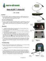
Aero-ALERT™ Alarm Kit
P/N: 100343, 101893, 101894
Function:
The Aero-ALERT™ alarm kit is designed to produce a visual and
audible signal when the Aero-Stream® product has an air output
of less than 1 PSI or a high water event with the optional high
water float switch. The product has a “mute” function to turn off
the alarm. The alarm will not function in the “mute” mode. In the
event of an alarm signal see the troubleshooting section below.
Service and Maintenance
The alarm is designed to produce the audible signal for at least 60
days and visual signal for at least 30 continuous days on the self
contained batteries. The batteries should be replaced annually. It
is suggested that they be replaced at the same time as your fire
detection smoke alarm in your home.
Directions
1. Install the air line/tee fitting in the output air line of the Aero-
Stream® unit. Clamp the air line with plastic clamp (figure 2).
2. Connect the 1/8” air line from the tee to the black barbed
fitting on the bottom of the Aero-ALERT™ (figure 3).
3. Push the Aero-ALERT™ post into the ground 3” - 5”. If the
earth is hard use a ¾” diameter wood or metal stake and a
hammer to make a 3” - 5” deep holes. Push the Aero-ALERT™
post into the formed hole. DO NOT HAMMER ON THE Aero-
ALERT™.
Troubleshooting
The light illuminates for two conditions, either a signal from the air
switch or a signal from the float switch. Follow the steps below to
determine the cause of the alarm.
1.
Unplug the float from the alarm box. If the light goes out go to
step 4. If the light does not go out go to step 2 (figure 4).
2.
Make sure the large air line connections are not leaking. If not
leaking go to step 3 (figure 2).
.
3.
Make sure the small air line is tightly connected to the black
“tee” and the fitting on the bottom of the alarm box. If the
To
Alarm
To Tank
From
Tee

PN 101953
Figure 4
Figure 5
Figure 6
connections are tight, pinch the large air line after the black “tee”
(on the tank side of the tee) to deadhead the pump. The sound
output of the pump will change. If the light goes out the air switch
is o.k. and go to step 4. If the light does not go out call Aero-
Stream®.
4.
Plug the float into the alarm box. Open the septic tank cover.
Make sure the float switch is hanging completely vertically in the
tank. If not, using a stick, push the float downward until the cord
and float are vertical. If the light goes out go to step 5.
5.
Allowing the float to hang from its’ bracket, adjust the float
switch clamp on the mast upward until the light goes out.
6.
If the light does not go out call Aero-Stream®.
Function Configuration
The Aero-ALERT™ can be configured to defeat the audible signal
or defeat the air switch to make the unit function as a high water
alarm only.
1. To defeat the audible signal gently slide the green connector
from the terminal and leave loose inside enclosure (figure 6).
2. To defeat the air switch gently slide the yellow connector from
the terminal and leave loose inside enclosure (figure 6).
Options:
P/N: 101859 - DC Power supply to operate the Aero-ALERT™ on
120 VAC.
Figure 7
To Float
Switch

PN 101953
Figure 8
Figure 9
Figure 10
Figure 11
Options: High Water Alarm Float
Directions
1. Remove the clean out cover on the septic tank and determine the
depth of the water in the tank and record.
2. Back out the screws in the receiver sections (figure 10) and insert
the mast sections into the receivers with the section containing the
float clamp at the upper most position. Tighten the screws until the
head of the screws bottom out on the receiver.
3. Using the measurement of the water depth in step 1, mark a line
on the side of the PVC pipe measuring from the bottom of the base
towards the top end of the pipe.
4. Slide the float clamp up or down so the bottom of the clamp is 2”
below the water mark and tighten clamp (figure 11).
5. Drill a 5/8” hole through the tank cover or the side of the riser to
allow the float switch cord to be pushed through.
6. Feed the free end of the float switch through the hole drilled in
step 5.
7. Lower the float assembly into the tank ensuring the pipe is in a
vertical position.
8. Pull the excess float switch cord through the hole and mark the
cord at the point it exits the tank.
9. Install the strain relief around the cord (figure 12) at the mark from
step 8.
10. Grasping and compressing the strain relief with a pliers, push it
into the 5/8” hole (figure 13). If the strain relief is pushed into
concrete, apply silicone caulk around the strain relief to seal out
water and hold in place.
11. Plug the free end of the float switch wire into the wire connector
on the Aero-ALERT™ (figure 4).
12. Burry the float switch cord 3” - 4” below the ground surface.
Water
Line
Clamp
Figure 12 Figure 13
Compress with
pliers
Push into
hole
/