Page is loading ...

1
CAUTION:
This manual is for
residential
fence only. All fence and gates must
be
installed to conform with B.O.C.A.
Specifications and/or local building code
regulations.
Note:
Local municipalities may require a
setback from property line to fence line,
otherwise, it is recommended to be 2”
inside the property line. It is important to
find out all the requirements before
installing your fence.
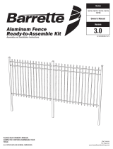
THE STRENGTH OF BEAUTY
RESIDENTIAL GRADE FENCE INSTALLATION MANUAL
2” between property
line and string
(See note above)
2”
STRING LINE
PROPERTY LINE
1/8” between
post and string
FIGURE 1
1. Layout and Planning
1.1. First stake out the area and run
strings around as shown in Figure 1.
1.2. Start by installing the gate posts.
See your gate installation manual
for proper gate post spacing.
1.3.
Proceed to dig post holes. Post
center to center measurement will
be 6’-
¾” when everything is level
and tight. See Figure 2 (on next
page) for post hole depth.
CAUTION: In areas where ground frost
occurs extend the concrete footing below
the frost line.
NOTE: Local municipalities may require
different hole depths than those shown
below. You must verify that these depths
meet all local building codes.
DT3327
-
20
GIVE THIS MANUAL TO THE HOMEOWNER UPON COMPLETION

2
Set concrete 4” below
ground surface to allow
grass to grow over
See chart at
right
Pack concrete 2”
below post or below
frost line whichever
is greater.
2” – 3” recommended for
easy lawn maintenance. 2”
maximum for pool fence.
POST DEPTH
HEIGHT DEPTH
Up to 4’ fence ≅ 18”
54” & 5’ fence ≅ 24”
6’ fence ≅ 30”
6” hole
diameter
FIGURE 2
2. Installation
2.1. Use a rubber mallet to drive the post caps
onto the posts. Be careful not to damage
the post or caps. See Figure 3.
2.2. Working out from where the gates are
installed slide a section of fence into the
gate post holes and into the next post. See
Figure 3. Fence sections must be
inserted entirely into the post to meet
code.
2.3. Fill the post hole with a stiff concrete mix
being sure that the concrete extends
below the bottom of the post.
2.4. Plumb the posts and pickets while the
concrete is setting. The fence section can
rake allowing the rails to follow the
contour of the ground. Brace the posts as
necessary while the concrete is setting.
2.5. Fence rails will need to be mitered for
corner posts. See Figure 4. Fence
sections may be cut to length as
necessary. Cut fence sections will need
to be notched as shown in Figure 5.
2.6. Additional hardware is available to attach
posts and rails to walls.
2.7. After concrete has set fasten the posts to
the fence with #8 x 1” self-drilling self-
tapping screws provided. Be careful not
to over-tighten because screw heads may
break off or the threads may strip out.
FIGURE 3
Post Cap
3/16”
¾”
¾”
¾”
Fence rail
(side view)
FIGURE 4
FIGURE 5
DELGARD FENCE COMPANY
8600 RIVER ROAD
DELAIR, NJ 08110-3398 USA
/