Page is loading ...

Installation Instructions:
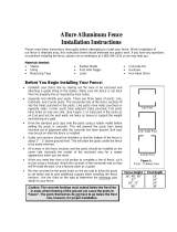
FIGURE 2
POST DEPTH
HEIGHT DEPTH
4 1/2’ fence ≅ 18”
Set concrete 4” below
ground surface to allow
grass to grow over
See chart at
right
2” – 3” recommended for
easy lawn maintenance. 2”
maximum for pool fence.
Pack concrete 2”
below post or below
frost line whichever
is greater.
6” hole
diamete
r
Post Cap
FIGURE 3
CAUTION: In areas where ground frost
occurs extend the concrete footing below
the frost line.
NOTE: Local municipalities may require
different hole depths than those shown
below. You must verify that these depths
meet all local building codes.
2. Post Installation
1/8” between
post and string
Note: Local municipalities may require a setback from property line to
fence line, otherwise, it is recommended to be 2” inside the property
line. It is important to find out all the requirements before installing
y
our fence.
2”
STRING
FIGURE 1
2” between property
line and string
(See note above)
PROPERTY
LINE
1. Layout and Planning
1.1. First stake out the area and run strings around
as shown in Figure 1. Gates need to be located
on level ground.
1.2. Proceed to dig post holes approximately 3” to
4” wider than the gate on centers See Figure
2 (on next page) for post hole depth.
1.3. Be sure to separate the gate posts from other
fence posts. Gate posts have a thicker wall
than other fence posts. To prevent your fence
from running short of the next gate post DO
NOT install more than one gate for each line
of fence to be installed. Additional gates will
be installed when the fence reaches the desired
gate location.
Call before you dig:
1 800 272 1000

Note: Like all mechanical devices, with age and wear, these hinges will require periodic lubrication,
readjustment and eventual replacement. Just as you manually lock your home for security, you must also
manually verify the gate is secured each time, as the self-closing motion could be hampered by wind, an
obstruction, etc. Remember, where children’s safety is involved, double check all barriers to prevent accidents.
2.1. Use a rubber mallet to drive the post caps onto the posts. Be careful not to
3. Gate Installation
actual width of the two gates. (Example: Two 36” wide gates will actually measure 70” wide
overall and will require the opening to be 72” wide.) See Figure 5.
2.4. Fill the post hole with a stiff concrete mix being sure that the concrete extends below the
bottom of the post.
2.5. Be sure the posts are plumb and the fence slots are facing the correct direction while the
concrete is setting. Brace the posts as necessary while the concrete is setting.
damage the post or caps. See Figure 3.
2.2. For a single gate installation set the gate opening 1”wider than the actual
gate. (example: a 36” wide gate actually measures 35” wide and will require
the actual gate opening to be 36” wide.) See Figure 4.
2.3. For a double drive gate installation set the gate opening 2” wider than the
3.1. After the concrete for the post has set the gate may be hung. Place the gate on blocks at the
correct elevation (See figure 2 above).
3.2. Locate the hinges as far apart as possible on the gate and clamp the hinge post leaf to the post.
Verify that the hinge post leaf is completely flush and plumb with the mounting surface, to
avoid binding. Note the direction the gate will open. See Figure 6.
3.3. Attach the hinges to the post by drilling 7/64” pilot holes and fastening with screws provided.
3.4. Center the gate into the opening and attach to the hinges in the same manner as the posts.
Double drive gates must have the diagonals running as shown in Figure 5.
3.5. If the hinge is to be mounted on a flat surface you may need to shim out the hinge post leafs so
that the hinge does not rub or bind against the mounting surface. See Figure 7.
3.6. The screws provided with the hinge are intended for securing the hinge to Delgard posts &
gates. If the hinge is to be mounted to a masonry column, wood, etc., ask your local building
supply dealer to recommend the appropriate fasteners for your mounting application.
3.7. Test gates for a smooth free swinging operation, then proceed to install the latch hardware as
needed.

Gate swing
direction
Gate
Leaf
Hinge
Gate
½” MAX
Gate
P
os
t
Fence
Section
4.3. Lubricate the hinges using a graphite based
lubricant. Apply lubricant to the top of each
hinge and remove excess lubricant from
painted surfaces.
5. Drop Rods
FIGURE 6
6. Regular Maintenance
6.1. Check for proper gate operation daily. Lubricate or adjust if necessary.
6.2. Keep gate and fence area free of debris and climbable objects.
6.3. Check fasteners for tightness and replace any worn or damaged parts.
5.1. Mount a drop rod guide two (2) inches from
the bottom of the gate by drilling two (2)
7/64” holes and fastening the guide with two
(2) # 6 x 1/2” self-tapping screws. Fasten the
drop rod catch 20 inches above the bottom of
the gate in the same fashion as the guide.
Before fastening the catch, use the drop rod
to align the guide and catch. See Figure 9.
FIGURE 8
FIGURE 9
Drop Rod
Catch
Drop Rod
Guide
/