Page is loading ...

Owner’s Manual
AIR COMPRESSOR
3-gallon
1 HP
Oil Lubricated
Model No. 921.153620
Sears Brands Management Corporation
Hoffman Estates, IL 60179 U.S.A.
www.sears.com/craftsman
02/18/2013
Part No. E106552
CAUTION:
Before using this product, read this
manual and follow all its Safety
Rules and Operating Instructions.
• SafetyInstructions
• Installation&Operation
• Maintenance&Storage
• TroubleshootingGuide
• PartsList

TABLE OF CONTENTS
Page
Warranty ................................................................ see below
Safety Symbols ...................................................................1
Important Safety Instructions & Guidelines ..............................................1
Specifications ....................................................................2
Glossary ........................................................................2
Duty Cycle .......................................................................2
Parts & Features ..................................................................3
Installation & Assembly .............................................................4
Operating Procedures ..............................................................6
Maintenance .....................................................................7
Storage .........................................................................7
Troubleshooting Guide .............................................................8
Exploded View ................................................................... 9
Parts List ...................................................................... 10
Service Number ...........................................................back cover
CRAFTSMAN ONE YEAR FULL WARRANTY
FOR ONE YEAR from the date of purchase, this product is warranted against any defects in material
or workmanship. A defective product will receive free repair or replacement if repair is unavailable.
For warranty coverage details to receive free repair or replacement, visit the web site: www.craftsman.com
This warranty is void if this product is ever used while providing commercial services or if rented to
another person.
This warranty gives you specific legal rights, and you may also have other rights which vary from state
to state.
Sears Brands Management Corporation, Hoffman Estates, IL 60179 U.S.A.

1
Safety Instructions
The information listed below should be read and
understood by the operator. This information is
given to protect the user while operating and stor-
ing the air compressor. We utilize the symbols
below to allow the reader to recognize important
information about their safety.
DANGER
Indicates an imminently hazardous situation
which, if not avoided, will result in death or seri-
ous injury.
CAUTION
Indicates a potentially hazardous situation
which, if not avoided, may result in minor or
moderate injury.
WARNING
Indicates a potentially hazardous situation
which, if not avoided, could result in death or
serious injury.
CAUTION
When used without the safety alert symbol indi-
cates a potentially hazardous situation which, if
not avoided, may result in property damage.
ImportantSafetyInstructionsandGuidelines
•Saveallinstructions
WARNING
Improper operation or maintenance of this product could result in serious injury and/or property
damage. Read and understand all of the warnings and safety instructions provided before using this
equipment.
CALIFORNIA PROPOSITION 65 WARNING: This product
contains chemicals known to the State of California to cause
cancer, birth defects and/or reproductive harm.
CAUTION
The air compressor should be operated on a dedicated 15 amp circuit. If
the circuit does not have 15 free amps available, a larger circuit must be
used. Always use more air hose before utilizing extension cords. All exten-
sion cords used must be 12 gauge with a maximum length of 25 ft. The
circuit fuse type must be a time delay. Low voltage could cause damage to
the motor.
RiskofMovingParts
If the air compressor is in operation, all guards and covers should be
attached or installed correctly. If any guard or cover has been damaged,
do not operate the equipment until the proper personnel has correctly re-
paired the equipment. The power cord should be free of any moving parts,
twisting and/or crimping while in use and while in storage.
Risk of Burns
There are surfaces on your air compressor that while in operation and
thereafter can cause serious burns if touched. The equipment should be
allowed time to cool before any maintenance is attempted. Items such as
the compressor pump and the outlet tube are normally hot during and after
operation.
Risk of Falling
Operation of the air compressor should always be in a position that is
stable. Never use the air compressor on a rooftop or elevated position that
could allow the unit to fall or be tipped over. Use additional air hose for
elevated jobs.
Risk from Flying Objects
Always wear ANSI Z87.1 approved safety glasses with side shields when
the air compressor is in use. Turn off the air compressor and drain the air
tank before performing any type of maintenance or disassembly of the
hoses or ttings. Never point any nozzle or sprayer toward any part of the
body or at other people or animals.

2
Important Safety Instructions & Guidelines
Risk to Breathing
Avoid using the air compressor in conned areas. Always have adequate
space (12 inches) on all sides of the air compressor. Also keep children,
pets, and others out of the area of operation. This air compressor does
not provide breathable air for anyone or any auxiliary breathing device.
Spraying material will always need to be in another area away from the air
compressor to not allow intake air to damage the air compressor lter.
Risk of Electrical Shock
Never utilize the air compressor in the rain or wet conditions. Any electrical
issues or repairs should be performed by authorized personnel such as an
electrician and should comply with all national and local electrical codes.
The air compressor should also have the proper three prong grounding
plug, correct voltage, and adequate fuse protection.
Risk of
Explosion or Fire
Never operate the compressor near combustible materials, gasoline or
solvent vapors. If spraying ammable materials, locate the air compressor
at least 20 feet away from the spray area. Never operate the air compres-
sor indoors or in a conned area.
Risk of Bursting
Always drain the air compressor tank daily or after each use. If the tank
develops a leak, then replace the air compressor. Never use the air com-
pressor after a leak has been found or try to make any modications to the
tank. Never modify the air compressor’s factory settings which control the
tank pressure or any other function.
Specifications
Pump ..................Oil-lube direct drive
Motor ...................1.0 HP (Induction)
Bore ...............................1.65”
Stroke ..............................1.26”
Voltage Single Phase ...............120 VAC
Minimum Circuit Requirement ........15 Amps
Air Tank Capacity .................3 Gallons
Cut-in Pressure ...................105 PSI
Cut-out Pressure ..................135 PSI
SCFM @ 90 PSI.......................2.4
Oil Capacity .................90 mL or 3 oz.
Oil Type . SAE 30 Non-detergent Semi Synthetic
Glossary
CFM: Cubic feet per minute.
SCFM: Standard cubic feet per minute; a unit of
measure for air delivery.
PSIG: Pounds per square inch gauge; a unit of
measure for pressure.
ASME: American Society of Mechanical Engineers.
California Code: Unit may comply with California
Code 462 (l) (2)/ (M) (2).
Cut-In Pressure: The air compressor will
automatically start to refill the tank when
the pressure drops below the prescribed
minimum.
Cut-Out Pressure: The point at which the motor
stops when the tank has reached maximum
air pressure.
Code Certification: Products that bear one or
more of the following marks: UL, CUL,
ETL, CSA, have been evaluated by OSHA-
certified independent safety laboratories
and meet the applicable Underwriters
Laboratories Standards for Safety.
Duty Cycle
This is a 50% duty cycle air compressor. Do not run the air compressor more than 30 minutes of
one hour. Doing so could damage the air compressor.

3
Parts&Features
See figures below for reference
Pressure
Relief Tube
Outlet Tube
Oil Fill Cap
OilSightGauge
Air Intake Filter
Provides clean air to the pump and must always be kept free of debris. Check on a daily basis or before each use.
RegulatorGauge
Indicates the outgoing air pressure to the tool and is
controlled by the regulator.
TankPressureGauge
Indicates the reserve air pressure in the tank.
Pressure Switch
This controls the power to the motor and
also the cut-in/cut-out pressure settings.
This switch serves as the Auto-On/Off
positions for the unit.
CheckValve
When the pump is not in operation, the valve closes to retain air pressure inside the tank. An internal component.
TankDrainValve
Used to drain condensation from the
air tank. Located at bottom of tank.
Quick Connect
Offers a quick release feature for attaching and
removing the air hose.
Regulator
The air pressure coming from
the air tank is controlled by the
regulator. To increase the
pressure, turn the knob clock
wise, and to decrease the
pressure, turn the knob counter
clockwise.
TankSafetyValve
Used to allow excess tank
pressure to escape into
the atmosphere. This valve
should only open when the
tank pressure is above the
maximum rated pressure.
PressureReliefValve
The pressure relief valve
located on the side of the
pressure switch, is designed
to automatically release
compressed air when the air
compressor reaches cut-out
pressure. The released
air should only escape
momentarily and the valve
should then close.

4
Installation&Assembly
WARNING
The air compressor should be turned off, unplugged from the power source, the air bled from the tank
and the unit allowed time to cool before any maintenance is performed. Personal injuries could occur
from moving parts, electrical sources, compressed air or hot surfaces. The quick connect assembly
must be attached before use. Failure to assemble correctly could result in leaks and possible injury. If
unsure of assembly instructions or you experience difculty in the assembly please contact your local
authorized Sears or another qualied service dealer.
Assembly
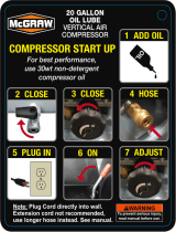
1. Remove air compressor, manual, air lter
assembly, and accessories from packaging.
2. Remove the plastic plug from the compressor
intake port. (see diagram below)
3. Install the lter in the compressor intake port.
(see diagram below)
4. Remove the oil ll cap from the crankcase and
ll until the oil reaches the top of the red dot in
the sight glass. Oil capacity is 3 oz. (see below)
Use SAE 30 Non-detergent Semi Synthetic
oil (API CG/CD heavy duty motor oil). Under
extreme cold weather conditions use SAE-10
weight oil.
5. Replace the oil cap.
1131
0
1E
A
N
OITNETT
LIO HT
IW L
LIF
ESU EROFEB
t
negr
ete
D
-
n
oN
03E
AS
432
Estimated Assembly Time:
Approximately 5 minutes

5
Grounded
Outlet
Grounding Pin
Plug
Make sure that the product is connected to an
outlet having the same conguration as the plug.
No adapter should be used with this product. If
the product must be reconnected for use on a
different type of electric circuit, qualied service
personnel should make the reconnection.
Extension Cords
Use only a 3-wire extension cord that has a
3-blade grounding plug, and a 3-slot receptacle
that will accept the plug on the product. Make
sure your extension cord is in good condition.
When using an extension cord, be sure to use
one heavy enough to carry the current your
product will draw. Cords must not exceed 25
feet and No. 12 AWG size must be used. An
undersized cord will cause a drop in line voltage
resulting in loss of power and overheating.
Break In Procedures
No break in procedure is required by the user.
This product is factory tested to ensure proper
operation and performance.
Installation & Assembly
GettingStarted-
Location of the Air Compressor
The air compressor should always be located
in a clean, dry and well ventilated environment.
The unit should have at minimum, 12 inches of
space on each side. The air lter intake should
be free of any debris or obstructions. Check the
air lter on a daily basis to make sure it is clean
and in working order.
GroundingInstructions
This product should be grounded. In the event of
an electrical short circuit, grounding reduces the
risk of electric shock by providing an escape wire
for the electric current. This product is equipped
with a cord having a grounding wire with an ap-
propriate grounding plug. (See the gure below.)
The plug must be plugged into an outlet that is
properly installed and grounded in accordance
with all local codes and ordinances. Check with
a qualied electrician or service personnel if
these instructions are not completely understood
or if in doubt as to whether the tool is properly
grounded.
Improper installation of the grounding plug will
result in a risk of electric shock. If repair or
replacement of the cord or plug is necessary,
do not connect the grounding wire to either at
blade terminal. The wire with insulation having
an outer surface that is green with or without
yellow stripes is the grounding wire. Check
with a qualied electrician or serviceman if
the grounding instructions are not completely
understood, or if in doubt as to whether the
product is properly grounded. Do not modify the
plug provided; if it will not t the outlet, have the
proper outlet installed by a qualied electrician.
This product is for use on a circuit having a
nominal rating of 120 volts and is factory-
equipped with a specic electric cord and plug
to permit connection to a proper electric circuit.
WARNING

6
Operating Procedures
Daily Shut-Down Procedures
1. Set the Auto-On/Off lever to the Off position.
2. Unplug the power cord from the receptacle.
3. Set the outlet pressure to zero on the regulator.
4. Remove any air tools or accessories. When
draining the tank, always use ear and eye
protection. Drain the tank in a suitable location;
condensation will be present in most cases
of draining.
5. Open the drain valve allowing air to bleed from
the tank. After all of the air has bled from
the tank, close the drain valve to prevent
debris buildup in the valve.
CAUTION
When draining the tank, always use ear and eye
protection. Drain the tank in a suitable location;
condensation will be present in most cases
of draining.
WARNING
Water that remains in the tank during storage
will corrode and weaken the air tank which could
cause the tank to rupture. To avoid serious injury,
be sure to drain the tank after each use or daily.
Daily Start-Up Procedures
1. Set the Auto-On/Off lever to the Off position.
2. Inspect the air compressor, air hose, and any
accessories/tools being used for damage or
obstruction. If any of these mentioned items
are in need of repair/replacement, contact
your local authorized service dealer before use.
3. Close the drain valve.
4. Check the oil level of the pump.
5. Connect the air hose to the quick connect
socket on the regulator assembly by inserting
the quick connect plug on the air hose into
the quick connect socket. The quick connect
socket collar will snap forward and lock
the plug into place providing an air tight seal
between the socket and plug. To release the
air hose push the collar back on the quick
connect socket.
6. Plug the power cord into the proper receptacle.
7. Turn the Auto-On/Off lever to the On-Auto
position and the compressor will start and
build air pressure in the tank to cut-out
pressure and then shut off automatically.
8. Adjust the regulator to a PSI setting that is
needed for your application and be sure it is
within the safety standards required to
perform the task. If using a pneumatic tool,
the manufacturer should have recommendations
in the manual for that particular tool on operating
PSI settings.
9. The air compressor is now ready for use.
1
4
7
5
3
8
6

7
Storage
For storing the air compressor, be sure to do the following:
1. Turn the unit off and unplug the power cord
from the receptacle.
2. Remove all air hoses, accessories, and air tools
from the air compressor.
3. Perform the daily maintenance schedule.
4. Open the drain valve to bleed all air from the tank.
5. Close the drain valve.
6. Store the air compressor in a clean and
dry location.
NOTE: Any service procedure not covered in the maintenance schedule should be performed
by qualified service personnel. Contact your local authorized Sears or another qualified ser-
vice dealer.
Maintenance
CAUTION
To ensure efcient operation and longer life of
the air compressor unit, a routine maintenance
schedule should be followed. The following
schedule is geared toward a consumer whose
compressor is used in a normal working environ-
ment on a daily basis.
WARNING
The air compressor should be turned off,
unplugged from the power source, air bled from
the tank and allowed time to cool before any
maintenance is performed.
Maintenance Schedule
Items to Check/Change
Before each use
or daily
Check Tank Safety Valve
X
Overall Unit Visual Check
X
Check Air Filter
X
Drain Tank
X
Check Power Cord for Damage
X
Change Oil
after first 50 hours
after every 100 hours
Check Oil Level
X
NOTES

8
WARNING
The air compressor should be turned off and unplugged from the power source before any mainte-
nance is performed as well as the air bled from the tank and the unit allowed time to cool. Personal
injuries could occur from moving parts, electrical sources, compressed air, or hot surfaces.
TroubleshootingGuide
PROBLEM POSSIBLE CORRECTION
Air leaks at the check
valve or at the pres-
sure relief valve.
A defective check valve results in a constant air leak at the pressure relief
valve when there is pressure in the tank and the compressor is shut off.
Drain the tank, then remove and clean or replace the check valve.
Air leaks between
head and cylinder.
Be sure of proper torque on head bolts. If leak remains, contact a service
technician.
Air leak from safety
valve.
Operate the safety valve manually by pulling on the ring. If the valve con-
tinues to leak when in the closed position, it should be replaced.
Pressure reading on
the regulated pressure
gauge drops when an
accessory is used.
If there is an excessive amount of pressure drop when the accessory is
used, replace the regulator.
NOTE:
Adjust the regulated pressure under ow conditions (while accessory is
being used). It is normal for the gauge to show minimal pressure loss
during initial use of the tool.
Excessive tank pres-
sure.
Move the Auto-On/Off lever to the Off position. If the unit doesn’t shut off,
unplug it from the power source and contact a service technician.
Motor will not start. Make sure power cord is plugged in and the switch is on. Inspect for the
proper size fuse in your circuit box. If the fuse was tripped, reset it and
restart the unit. If repeated tripping occurs, replace the check valve or
contact a service technician.
Excessive moisture in
the discharge air.
Remove the water in the tank by draining after each use. High humidity
environments will cause excessive condensation. Utilize water lters on
your air line.
NOTE:
Water condensation is not caused by compressor malfunction. Be sure
the compressor’s air output is greater than your tool’s air consumption
rate.
Air leaks from the tank
body or tank welds.
Never drill into, weld or otherwise modify the air tank or it will weaken.
The tank can rupture or explode. Compressor cannot be repaired. Dis-
continue use of the air compressor.

9
Craftsman Air Compressor Model 921.153620
Exploded View
1
2
3
4
5
6
7
8
9
10
2
11
12
13
14
15
16
17
18
19
20
21
22
23
24
25
28
26
27
30
31
32
33
34
35
36
37
38
39
40
41
42
43
44
45
46
47
48
45
46
49
46
44
51
52
53
54
55
56
57
58
59
60
61
62
63
64
65
66
45
46
48
50

10
Craftsman Air Compressor Model 921.153620 Parts List
Ref.
#
Kit
#
Part
Number
Description Qty
1 3 Screw, M6 X 1.0mm
X 30mm
4
2 3 Washer, Lock M6 8
3 3 E100227 Head, Cylinder 1
4 1 & 3 Gasket, Head to Valve
Plate
1
5 3 E100228 Plate, Valve 2
6 3 E100229 Valve Reed 2
7 1 & 3 Gasket, Valve Plate 1
8 1 & 3 E100228 Gasket, Cylinder to
Valve Plate
1
9 2 & 3 E101113 Cylinder 1
10 3 Screw, SHC M6 x 1.0
x 20MM
4
11 1 & 3 Gasket, Cylinder,
Lower
1
12 2 & 3 Eccentric for L1 1
13 2 & 3 Nut, Hex, M6x1.0 3
14 2 & 3 Screw, SHC M6 x 1.0
x 20MM
1
15 2 & 3 L1 Piston/ Connecting
Rod Assembly
1
16 1 & 3 Baffle for L1 1
17 3 E100087 Cap, Oil Fill w/o-ring 1
18 3 E100566 Cover, Crankcase
for L1
1
19 3 E100078 Plug, oil sight w/seal 1
20 3 Screw, HFH M5 x 0.8
x 15MM (Yellow Zinc
Dich Plate)
4
21 3 Motor Assembly/Pump
Housing LS1B2
1
22 3 E100860 Fan, Motor F1 125mm 1
23 3 Ring, Snap, Outer,
15mm
1
24 3 E100247 Capacitor, Running 1
25 3 E100248 Capacitor, Starting 1
26 3 Washer, Tooth Lock,
8mm
2
27 3 Nut, M8x1.25, ZDC
6.5MM TALL
6
28 3 E106599 Guard, Capacitor 1
29 N/A
Ref.
#
Kit
#
Part
Number
Description Qty
30 3 Assembly, Motor/
Pump, L1B2 w/RH
Exhaust
1
31 E100809 Fitting, Elbow, 3/8NPT
x 3/8 Comp
1
32 4 Base, Air Filter 1
33 4 E100435 Element, Intake Filter 1
34 4 Cover, Filter 1
35 E105620 Handle 1
36 E106573 Grip, Rubber 1
37 5 Ferrule, 1/4” 2
38 5 Nut, Comp, 1/4” 2
39 5 Tube, Relief 1/4”
Aluminum
1
40 6 Ferrule, 3/8” 2
41 6 Nut, Comp, 3/8” 2
42 6 Tube, Outlet 3/8” Alumi-
num Finned
1
43 E101362 Valve, Check LH 1
44 Bolt, SHC M8 x 1.25 x
25mm ( ZDC Plate)
6
45 Washer, Lock, M8 10
46 Washer, Flat M8 14
47 Tank/Frame Assy, 3
Gallon, L13HPS
1
48 Nut, M8x1.25 ZDC 4
49 E100240 Isolator, Rubber 4
50 E100098 Valve, Drain Multi-Turn 1
51 E102822 Quick Connect, Steel 1
52 E100059 Regulator, Square Body
LH Flow
1
53 E102857 Nipple, 1/4”NPT X 43MM 1
54 E100594 Strain Relief, 14/3 AWG
SJT
1
55 E100853 Nipple, 1/4”NPT X 35MM 1
56 E101073 Cord, Power 14/3 AWG
type SJT 6’ long
1
57 E100594 Strain Relief, 14/3 AWG
SJT
1
58 E102611 Valve, Safety 1
59 E106477 Assy, Switch, Pressure
(135 PSI)
1
60 E103363 Gauge, Pressure,
(38mm w/135 PSI R/L)
1

11
NOTES
Craftsman Air Compressor Model 921.153620 Parts List
Note: Any part/kit number field without a number is not avail-
able. Descriptions are provided for reference only. The Kit #
column represents that the part being offered is available in a
kit. One of each part per kit will be offered.
Kit
No.
Part No. Description
Refer-
ence No.
1 E100959 Kit, Gasket Rebuild 4,7,8,11,16
2 E100251
Kit, Piston - (Note: Order
Gasket Kit #1, as well,
when ordering this kit)
9,12 thru15
3 E106555
Kit, LS1B2 Motor/Pump
Assy. w/RH Exhaust
1 - 27, 30
4 E100794 Kit, Air Filter 32-34
5 E105953
Kit, 1/4” Cu Pressure
Relief Tube
37-39
6 E105952
Kit, 3/8” Aluminum Outlet
Tube
40-42
Ref.
#
Kit
#
Part
Number
Description Qty
61
E104568
Ring, Bezel Tank (38
mm)
1
62
E103369
Gauge, Pressure,
(50mm 135 PSI R/L,
1/4” NPT)
1
63
E104074
Ring, Bezel Tool (50
mm)
1
64
Screw, Hex Flange
Head, M5X0.8X15mm
6
65
E105615 Shroud
1
66
Screw, SHC, M8 x 1.25
x 16mm
4
Kit number and parts that are included are as follows:

NOTES / NOTAS

Manual de
COMPRESOR DE AIRE
11.36 litros
1 HP
Lubricada con aceite
# de Modelo. 921.153620
Sears Brands Management Corporation
Hoffman Estates, IL 60179 U.S.A.
www.sears.com/craftsman
02/18/2013
Part No.E106552
PRECAUCIÓN:
Antes de usar el producto, lea este
manual y siga sus reglas e instruc-
ciones de seguridad.
• Instruccionesypautasde
seguridad importantes
• Instalaciónyensamblaje
• Procedimientosdeoperación
• MantenimientoyAlmacenamiento
• Diagnósticoycorreccióndefallas
• Listadelaspiezas

CONTENIDO
Página
Garantía. . . . . . . . . . . . . . . . . . . . . . . . . . . . . . . . . . . . . . . . . . . . . . . . . . . . . . . . . . . . . . . . esta página
Símbolos de seguridad ............................................................15
Instrucciones y pautas de seguridad importantes ........................................15
Especificaciones .................................................................16
Glosario ........................................................................16
Ciclo de trabajo ..................................................................16
Partes y características ............................................................17
Instalación y ensamblaje ...........................................................18
Procedimientos de operación .......................................................20
Mantenimiento ...................................................................21
Almacenamiento .................................................................21
Diagnóstico y corrección de fallas. . . . . . . . . . . . . . . . . . . . . . . . . . . . . . . . . . . . . . . . . . . . . . . . . . . .22
Vista esquemática ...............................................................23
Lista de las piezas ............................................................... 24
Número de servicio ........................................................Contratapa
UNAÑODEGARANTÍADECRAFTSMAN
DURANTE UN AÑO desde la fecha de compra, este producto tiene garantía contra defectos en los
materiales o en la fabricación. Los productos defectuosos se repararán gratuitamente o se reemplaz-
arán sin coste si la reparación no es possible.
Para conocer los detalles de cobertura de la garantía con el fin de obtener una reparación o un reem-
plazo, visite el sitio web www.craftsman.com
Esta garantía no es válida si el producto se utiliza para proporcionar servicios comercíales o si se
alquila a un tercero.
Esta garantía le proporciona derechos legales específicos y es posible que además tenga otros
derechos, dependiendo del país o el estado.
Sears Brands Management Corporation, Hoffman Estates, IL 60179 EE. UU.

15
Instrucciones de seguridad
El operador debe leer y entender la información si-
guiente. Esta información se ofrece para proteger
al usuario durante la operación y el almacenaje
del compresor. Los símbolos siguientes son los
que se utilizan para indicar al lector información
que es importante para su seguridad.
PELIGRO
Indica una situación de riesgo inminente que,
de no evitarse, provocaría lesiones graves o la
muerte.
PRECAUCIÓN
Indica una situación potencialmente peligrosa
que, de no evitarse, podría provocar lesiones
menores o moderadas.
ADVERTENCIA
Indica una situación potencialmente peligrosa
que, de no evitarse, podría provocar lesiones
graves o la muerte.
PRECAUCIÓN
Al aparecer sin el símbolo de alerta de se-
guridad, indica una situación potencialmente
peligrosa que, de no evitarse, podría causar
daños materiales.
Instrucciones y pautas de seguridad importantes
•Guardetodaslasinstrucciones
ADVERTENCIA
La operación y el mantenimiento inadecuados de este producto pueden provocar lesiones graves y
daños materiales. Antes de utilizar este equipo, lea y entienda las advertencias e instrucciones de
seguridad aquí contenidas.
ADVERTENCIA DE LA PROPUESTA DE LEY 65 DE CALIFORNIA: Este
producto contiene substancias químicas que, consta al Estado de California,
producen cáncer, malformaciones congénitas o daños reproductivos.
PRECAUCIÓN
El compresor de aire se debe operar desde un circuito dedicado de 15
amperes. Si el circuito no dispone de una capacidad de 15 amperes,
se debe usar un circuito de mayor capacidad. Si es necesario, antes de
emplear una extensión eléctrica, añada una manguera de aire más larga.
Las extensiones eléctricas deben ser de calibre 12 y tener una longitud
máxima de 7.6 metros. El fusible del circuito debe ser de acción
retardada. Un voltaje demasiado bajo puede dañar el motor.
Riesgo por partes en
movimiento
Antes de operar el compresor, todos los protectores y cubiertas deben
estar instalados correctamente. Si alguno de los protectores o cubiertas
está dañado, no opere el equipo sino hasta que personal calicado repare
el problema. El cable de corriente se debe mantener alejado de las partes
móviles del equipo y no debe torcerse ni prensarse durante su empleo ni
al ser almacenado.
Riesgo de quemaduras
En su compresor hay supercies que, de ser tocadas durante y después
de su operación, pueden causar quemaduras graves. Antes de darle
mantenimiento al equipo, se le debe dejar enfriar. Por lo normal, durante y
después de su operación, ciertas partes como la bomba del compresor y
el tubo de salida estarán calientes.
Riesgo de caída
El compresor siempre se debe operar en una posición estable. Nunca
utilice el compresor sobre un techo o en una posición elevada desde
donde podría caer o volcarse. Al trabajar en posiciones elevadas, utilice
una manguera de aire más larga.
Riesgodelanzamiento
de objetos
Al emplear el compresor, siempre utilice anteojos de seguridad con
protectores laterales que cumplan con la norma ANSI Z87.1. Antes de
llevar a cabo cualquier clase de mantenimiento y antes de desconectar las
mangueras y acopladores, apague el compresor y drene el tanque de aire.
Nunca apunte la boquilla o rociador hacia ninguna parte de su cuerpo ni
del de otros seres.

16
Instrucciones y pautas de seguridad importantes
Riesgo para la
respiración
Evite utilizar el compresor de aire en áreas encerradas. Siempre tenga
un espacio libre adecuado (30 cm.) en todos los lados del compresor.
También mantenga fuera del área de operación a mascotas, niños y otras
personas. Este compresor de aire no provee aire que pueda ser respirado
ni empleado con un dispositivo respiratorio auxiliar. El material de rociado
siempre deberá estar en otra zona, alejado del compresor de aire, para
evitar que el aire aspirado dañe el ltro del compresor.
Riesgo de descargas
eléctricas
Nunca utilice el compresor de aire bajo lluvia o en lugares mojados. Los
problemas eléctricos deben ser reparados por personal autorizado, tal
como sería un electricista, y deben cumplir con las normas eléctricas
nacionales y locales. El compresor también debe tener la clavija apropiada
de tres terminales y contar con un suministro eléctrico que sea del voltaje
correcto y con un fusible de protección adecuado.
Riesgodeexplosión
y fuego
Nunca opere el compresor cerca de materiales combustibles, gasolina ni
vapores de solventes. Si está rociando materiales inamables, coloque el
compresor a una distancia de cuando menos 6 metros del área de rocia-
do. Nunca opere el compresor de aire en interiores o en lugares cerrados.
Riesgo de estallido
Drene el compresor diariamente o después de cada utilización. Si el
tanque tiene una fuga, reemplace el compresor. No utilice el compresor si
se ha detectado una fuga, ni trate de modicar el tanque. Nunca modique
los ajustes de fábrica del compresor que controlan la presión del tanque y
demás funciones.
Especificaciones
Bomba ......................De impulsión
. . . . . . . . . . . . . . . . directa, lubricada con aceite
Motor ...................1.0 HP (Inducción)
Diámetro..........................42 mm
Carrera ............................3 mm
Voltaje monofásico .................120 VAC
Capacidad mínima del circuito...........15 A
Capacidad del tanque de aire ......11.36 litros
Presión de arranque...... 724.0 KPa / 105 PSI
Presión de parada .......930.8 KPa / 135 PSI
Pies cúbicos por minuto (SCFM) a 90 LPPC. 2.4
Capacidad del aceite ........ 90 ml o 3 onzas.
Tipo de aceite ...... Tipo de aceite - SAE 30 /
. . . . . . . . . . . . . . no detergente – semi-sintético
Glosario
CFM: Pies cúbicos por minuto.
SCFM: Pies cúbicos estándar por minuto; unidad
de medición de suministro de aire.
PSIG: Libras por pulgada cuadrada sobre la
presión atmosférica; unidad de medición de
presión.
ASME: Sociedad estadounidense de ingenieros
mecánicos.
CódigodeCalifornia: La unidad puede cumplir con
el código de California 462 (l) (2)/ (M) (2).
Presióndearranque: El compresor arranca
automáticamente cuando la presión baja a
menos del mínimo prescrito.
Presióndeparada: Presión de aire que tiene
que alcanzarse en el tanque para que se
detenga el motor.
Certificacióndecódigo: Los productos que tienen
alguna o varias de las siguientes marcas
han sido evaluados por laboratorios de
seguridad independientes certificados
por OSHA, y cumplen con las normas de
seguridad de Underwriters Laboratories:
UL, CUL, ETL, CSA.
Ciclo de trabajo
Este compresor tiene un ciclo de trabajo de 50%. Nunca opere el compresor por más de 30 minutos
cada hora. De hacerlo, podría dañarlo.

17
Partes y características
Como referencia, vea las figuras abajo
Filtro de aire
Suministra aire limpio a la bomba. Siempre se le debe tener libre de suciedad. Revíselo diariamente o antes
de cada uso. (Véase la imagen en la sección de ensamblaje.
Manómetrodepresióndesalida
Indica la presión de salida del aire que se entrega a la
herramienta, presión que es controlada por el regula
dor.
Manómetrodepresióndeltanque
Indica la presión de la reserva de aire del tanque.
Válvula de retención
Cuando la bomba no está en operación, esta válvula se cierra para retener la presión de aire dentro del
tanque. Es un componente interno.
Tubodealivio
depresión
Tubo de salida
Tapóndellenado
de aceite
Visor de aceite
Regulador
La presión del aire que sal del tanque
es controlada por el regulador. Para
aumentar la presión, gire la perilla en
dirección de las manecillas; para
disminuirla, gire la perilla en dirección
contraria a las manecillas.
Válvuladealiviode
presión
Esta válvula, que se
encuentra en el costado
del interruptor de presión,
está diseñada para liberar
aire comprimido de
manera automática cuando
el compresor llegue a la
presión de parada. El aire
sólo deberá escapar duran
te un instante, cerrándose
la válvula en seguida.
Válvuladedrenado
Sirve para drenar la condensación acumulada
en el fondo del tanque. Se encuentra en la
parte inferior del tanque.
Conector de acoplamiento rápido
Permite conectar y desconectar rápidamente la
manguera de aire.
Válvuladeseguridaddel
tanque
Used to allow excess tank
pressure to escape into
the atmosphere. This valve
should only open when the
tank pressure is above the
maximum rated pressure.
Interruptordepresión
Controla el suministro eléctrico al motor
y también los ajustes de presión de
arranque
y presión de parada. Este inter
ruptor sirve como posición de autoen
cendido y apaga do (Auto-On/Off) de la
unidad.

18
Instalaciónyensamblaje
ADVERTENCIA
Antes de realizar cualquier instalación y ensamblaje al compresor de aire, se lo debe apagar y desco-
nectar del generador, además de purgar el aire del tanque y darle suciente tiempo para enfriarse.
Existe el riesgo de que las partes móviles, la fuente eléctrica, el aire comprimido y las supercies
calientes provoquen lesiones. El ensamble del regulador debe estar instalado antes de usar el com-
presor. Un ensamblaje inadecuado puede ser causa de fugas y posiblemente de lesiones. Si no está
seguro de entender las instrucciones de ensamblaje o tiene dicultad para llevar a cabo el armado,
por favor llame a su departamento local de servicio.
Ensamblaje
1. Remueva el compresor de aire, manual,
ensamblaje del ltro de aire y accesorios de
la empaquetadura.
2. Remueva el tapón de plástico de la salida de
aire del compresor. (ver abajo)
3. Instalar el ltro dentro de la entrada de aire
del compresor. (ver abajo)
4. Remueva la tapa del tanque de aceite del
cárter del motor y llénelo hasta llegar el punto
rojo marcado en el vidrio transparente. La
capacidad de aceite es 3oz (ver abajo). Utilice
Tipo de aceite - SAE 30 / no detergente
– semi-sintético (API CG/CD aceite para
motores de gran capacidad). En caso de fríos
extremos utilice aceite pesado SAE-10.
5. Coloque nuevamente la tapa del tanque de
aceite.
1131
0
1E
A
N
OITNETT
LIO HT
IW L
LIF
ESU EROFEB
t
negr
ete
D
-
n
oN
03E
AS
432
Tiempo estimado de ensamblaje:
Aproximadamente 5 minutos
/