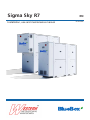
Western Sigma Sky OH / Hi OH / HPW R7 Installation and Operating Instructions
- Category
- Heat pumps
- Type
- Installation and Operating Instructions
This manual is also suitable for

Sigma Sky R7 EN
09-03-2022
Installation, use and maintenance manual

2We reserve the right to make changes without any prior notice.Translation from original instructions
THANK YOU
Thank you for choosing our product.
It is the result of many years’ experience and careful design and has been built with rst-class quality materials and advan-
ced technologies.
Declaration of conformity also guarantees that the equipment meets the requirements of the European Machinery Safety
Directive.
The quality level is constantly monitored, and therefore our products are synonymous with Safety, Quality and Reliability.
Changes considered necessary for product improvement may be made to the stated data at any time without any obligation
to give prior notice.
Thank you again
Read this manual carefully before installing, testing or starting this unit.
Give this manual and all complementary documentation to the operator of the system who will be responsible
for keeping them so they are always available if needed.
The images and drawings contained herein are examples only.

3
We reserve the right to make changes without any prior notice. Translation from original instructions
Contents
1 Introduction 6
1.1 Conformity 6
1.2 Description 6
1.2.1 Symbols 6
1.2.2 Labels 7
2 Safety 8
2.1 General safety precautions 8
2.1.1 Dischargeofthesafetyvalves 9
2.1.2 Emergencystop 10
2.2 Basic rules 11
2.2.1 Waterowrateattheheatexchangers 12
2.2.2 Watercomposition 12
2.2.3 Minimumwatercontentinthesystem 13
2.2.4 Installingtheowswitch 14
2.2.5 Operationwithwatertotheevaporatoratlowtemperature 15
2.2.6 Operationwithwatertothecondenseratlowtemperature 15
2.2.7 Condensationcontrolatthesourcehydrauliccircuit 16
2.2.8 Hydraulicconnectiontotheheatrecuperator(DCoption) 18
2.2.9 Hydraulicconnectiontothedesuperheater(DSoption) 19
2.2.10 Refrigerantleakdetector 20
2.3 Noise 21
2.4 Residual risks 21
2.5 Safety information on the refrigerant uid 23
2.5.1 Hazardsandhealthconsequences 23
3 Receiving the product and storage 24
3.1 Reception 24
3.2 Transport 24
3.3 Handling 25
3.4 Storage 27
4 Ecodesign conformity 28
4.1 Documentation supplied with the product 28
4.1.1 UnitsconformingtoallECrequirementsincludingtheEcodesignDirective 28
4.1.2 UnitsexemptfromtheEcodesignDirectiveandingeneralconformingtoallECrequirements 28
4.1.3 Partlycompletedmachine 29
4.1.4 ApplicableDocumentsenvisagedwithregardtothetypeofunit 29
4.1.5 Eciencyparametersrequiredforconformity 29
4.2 Conformity of the application 30
5 Product description 31
5.1 Intended use 31

4We reserve the right to make changes without any prior notice.Translation from original instructions
5.2 Unintended use 31
5.3 Control and safety devices 32
5.4 Principles of operation 32
5.5 Structure 32
5.6 Specications 32
5.7 Control panel 33
5.7.1 Switchingtheuniton/o 33
5.7.2 Changingtheheatingsetpoint 33
5.7.3 Editing“ACS”setpoint 33
5.8 Wiring diagram 33
6 Installation 34
6.1 Dimensions and weight 34
6.2 Place of installation 34
6.3 Installation 35
6.3.1 Positioningtheunits 35
6.3.2 Anti-vibrationmounts 35
6.3.3 Noiseattenuation 36
6.3.4 Minimumdistances 36
6.4 Hydraulic connections 37
6.4.1 Userhydrauliccircuit 38
6.4.2 Sourcehydrauliccircuit 39
6.4.3 Recoveryhydrauliccircuit 40
6.4.4 Hydrauliccircuitforheatpumpunitswithreversalonthewater 41
6.4.5 Connectionofseparatehydraulicmodule,“OptionMIS” 41
6.5 System components 42
6.5.1 Installationofpressuresensors 42
6.5.2 Installationoftemperaturesensor 43
6.6 Electrical connections 44
7 Commissioning 46
7.1 Preliminary operations 46
7.1.1 Checkingthepre-chargeoftheexpansionvessel 47
7.1.2 Checkingthevolumeoftheexpansionvessel 48
7.2 First starting 49
7.2.1 Hydraulictests 49
7.2.2 Start 49
7.2.3 Functionaltests 50
7.3 System testing 51
7.3.1 FlowzerVP 51
7.3.2 FlowzerDT 52
7.3.3 FlowzerVDE 56
7.3.4 FlowzerVD 57

5
We reserve the right to make changes without any prior notice. Translation from original instructions
7.3.5 FlowzerVFPP 59
7.3.6 FlowzerVPS 62
7.4 Calibration of safety components 65
7.5 Checks during operation 66
7.6 Alarms and malfunctions 67
7.6.1 Generaltroubleshooting 67
7.7 Temporary stop 69
7.8 Stop for long periods of time 69
8 Maintenance 70
8.1 Adjustments 70
8.2 Internal cleaning 71
8.2.1 Cleaningtheunit 71
8.2.2 Cleaningtheplateheatexchangers 71
8.3 Periodic checks 72
8.4 Unscheduled maintenance 73
8.4.1 Specialwork 73
9 Decommissioning 74

6We reserve the right to make changes without any prior notice.Translation from original instructions
1 INTRODUCTION
1.1 Conformity
With regard to relevant regulations and directives, see the declaration of conformity that is an integral part of the manual.
1.2 Description
1.2.1 Symbols
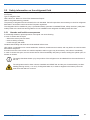
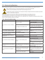
A description of the main symbols used in this manual and on the labels axed to the unit is given below.
Danger symbol; take extreme care.
Danger symbol; moving mechanical parts.
Danger symbol; live parts.
Warning symbol; important information
Note symbol; suggestions and advice
Danger sign: ammable gas.

7
We reserve the right to make changes without any prior notice. Translation from original instructions
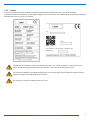
1.2.2 Labels
For the constructional features, available models and technical data, please refer to the Technical Catalogue.
The model, serial number, features, power supply voltage and so on are shown on the labels axed to the unit (the following
illustrations are shown only as an example).
The Manufacturer adopts a continuous development policy and, in this perspective, reserves the right to
make changes and improvements to the documentation and to the units without prior notice.
The Technical Catalogue, the labels placed directly on the unit and the various diagrams referred to below,
must be considered an integral part of this manual.
Do not remove or alter the labels placed on the unit.

8We reserve the right to make changes without any prior notice.Translation from original instructions
2 SAFETY
2.1 General safety precautions
Access to the area around the unit must be prevented by special guarding where this is positioned in a location that is not
protected and can be reached by unqualied persons.
The equipment operator is responsible for complying with regulatory obligations.
The equipment operator is the person who has actual control over the technical operation and free access, which means
the possibility of monitoring its components and their operation and the possibility of granting access to third parties.
The equipment operator has the power to decide on technical modications, checks and repairs.
The equipment operator may give instructions to employees or to external companies for carrying out maintenance and
repair operations.
Access to the unit must be granted exclusively to technicians authorised by the equipment operator.
The equipment must be installed and maintained or repaired by sta and contractors who hold a relevant certicate issued
by a certication body. Within Europe, the certication body must be designated by a member state to certify compliance
with the requirements laid down in Regulation (EU) No 517/2014 of the European Parliament and of the Council of 16 April
2014 on uorinated greenhouse gases and repealing Regulation (EC) No 842/2006 Text with EEA relevance.
Any operator gaining access to the unit must be authorised and qualied as specied in the local legislation and in Europe-
an standards EN378-4 and EN13313. Additionally, they must have proper knowledge to perform all the activities required
throughout the service life of the machine.
Access to the unit requires that the closing panels, where tted, are removed.
On no account must unqualied personnel be allowed to enter the unit and no one should be allowed to enter before the
power to it has been turned o.
The user can interact with the unit only through the control and external OK signals.
Only authorised knowledgeable personnel may access the unit in compliance with safety in the workplace regulations. At
European level, refer to Council Directive 89/391/EEC of 12 June 1989 on the introduction of measures to encourage im-
provements in the health and safety of workers at work.
Also, knowledge and understanding of the manual are indispensable for reducing risks and for improving the health and
safety of workers.
The operator must know what to do when faced with possible anomalies, malfunctions or conditions of danger to himself or
others, and in any case, he must comply with the following instructions:
Stop the unit immediately by using the emergency device.
Do not do anything that goes beyond your duties and technical knowledge.
Inform the manager immediately and do not take personal initiatives.
Before carrying out any work on the unit, make sure you have turned o the power supply to it. Refer to the
section on maintenance work.
Before work is started on the unit: check for potentially ammable atmospheres; Make sure there are no
possible ignition sources Adhere to the requirements set by the local legislation and by European standards
EN378-4 and EN13313.

9
We reserve the right to make changes without any prior notice. Translation from original instructions
In units with capacitors and/or inverters, certain components can remain live for several minutes even after
having turned o the main switch.
Wait 10 minutes before working on the electrical parts of the unit.
Circuits supplied from external sources (made with orange cable) can remain live even after the power sup-
ply to the unit has been turned o.
Work on the unit only if there is sucient lighting for the type of work to be carried out.
Failure to comply with the instructions in this manual and any modications made to the unit without prior written consent,
will immediately void the warranty.
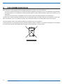
The law regulating the use of stratospheric ozone depleting substances prohibits the release of refrigerant
gases into the environment and obliges owners to recover and return them to the dealer or take them to spe-
cial collection centres at the end of their operational life.
The refrigerant contained in the refrigerant circuit is included among the substances subject to special con-
trol regulations provided for by law and must therefore be disposed of as indicated above.
Particular care should be taken during maintenance operations in order to reduce refrigerant leaks as much
as possible.
Before you open the electrical cabinet after a recent refrigerant leakage, make sure that there is no gas in
the air using a gas detector.
2.1.1 Discharge of the safety valves
If present on the refrigerant circuit, installation requirements and/or national regulations lay down that the discharge of the
safety valves must be routed to the outside.
The conveying must be done with a pipe whose diameter must be at least that of the valve outlet, and the weight of the pipe
must not be borne by the valve.
Always direct the discharge to areas where the jet cannot cause harm to anyone.
Risk of burns following contact with hot and cold parts.
any material exhausted from the safety valves must be conveyed using pipes in compliance with the natio-
nal and/or European directives: the exhaust point must not be close to trap-doors, manhole covers and any
other opening where refrigerant may be contained; exhausted material must not be conveyed close to fresh
air inlets, doors or similar openings; exhausted material must not be conveyed close to ignition sources, as
dened in standard EN378-2.
According to the denition given in standard EN378-1, the site of installation of these units is dened as
category III, i.e. no restriction applies as to the amount of refrigerant contained in the unit.
It is responsibility of the installer to carry out a ammability risk assessment and a classication of the dan-
ger zone at the site of installation, as required by standard EN378-3 and/or the national regulations in place.
Standard EN13136:2019 should be referenced for the calculation and sizing of the safety valve exhaust.

10 We reserve the right to make changes without any prior notice.Translation from original instructions
Zone 2 forming from the emissions of a safety valve may extend horizontally up to 10 metres and vertically
up to 11 metres.
The installer is responsible for assessing the risk areas.
Exhausted material must not be conveyed close to ignition sources, as dened in standard EN378-2.
Where the existing local regulations are more stringent, these should be taken as reference.
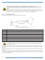
The table below shows the min. inner diameter to be used in order for the head losses downline of the safety valve to be in
compliance with standard EN13136:2019 (7.4.1), along a max. length of 10 metres and 8 curves.
For Sigma Sky R7 units
Size 4.2 5.2 6.2 7.2 8.2 9.2 11.2 12.2 14.2 15.2 17.2 19.2 20.2
Φ [mm] 35 38 40 42 45 48
Size 16.4 19.4 21.4 24.4 27.4 30.4 35.4 40.4 45.4 50.4 57.5 65.6
Φ [mm] 38 40 42 45 48 54 62
For Sigma Sky Hi R7 units
Size 4.1 6.1 8.2 10.2 12.2
Φ [mm] 35 38 40
A threaded connector is provided on the top part (reference “A”) to connect the exhaust pipe of the safety valve.
Refer to the dimensional diagram for the required diameters.
A
Fig. 1 Connection to convey the material exhausted from the safety valve
As two safety valves are tted in units featuring two circuits, each valve needs to have its independent drain
ducting.
2.1.2 Emergency stop
In case of emergency, an immediate stop is carried out using the red disconnecting switch/master switch on the electrical
control panel by turning it to 0. When it is turned to 0, the disconnecting switch turns o the power to the whole unit.
The main disconnect switch/master switch, used to electrically isolate the unit, is also intended for use as an
emergency device and it is only in an emergency that it should be used to stop the unit.
Except the case of an emergency stop, the unit must be stopped using its control software.

11
We reserve the right to make changes without any prior notice. Translation from original instructions
2.2 Basic rules
All units are designed and manufactured in accordance with the applicable European Directives that are referenced in the
declaration of conformity.
To ensure maximum safety, in order to prevent possible risks, follow the instructions below:
- this product contains pressurised vessels, live components, moving mechanical parts and very hot and cold surfaces
that, in certain situations, can pose a risk: all maintenance work must be carried out by skilled personnel equipped with
the necessary qualications in accordance with current regulations. Before carrying out any operation, make sure that
the personnel in charge has full knowledge of the documentation supplied with the unit.
- always have a copy of the documentation near the unit.
- The operations indicated in this manual must be integrated with the procedures indicated in the user instruction manuals
of the other systems and devices incorporated in the unit. The manuals contain all the necessary information for safely
managing the devices and the possible operating modes.
- use suitable protection (gloves, hard hat, protective glasses, safety shoes, etc.) for all maintenance or control opera-
tions carried out on the unit.
- Do not wear loose clothing, ties, chains, watches, etc., which can get caught in the moving parts of the unit.
- always use tools and protective equipment in excellent condition.
- The compressors and delivery gas pipes are at high temperature. Therefore, when working in the immediate vicinity, be
careful to avoid touching any components of the unit without suitable protection.
- do not work in the discharge trajectory of the safety valves.
- if the units are positioned in unprotected places which can easily be reached by unqualied persons, suitable protection
devices must be installed.
- the user must consult the installation and use system manuals, incorporated and attached to this manual.
- there may be potential risks that are not obvious. Warnings and signals are therefore displayed on the unit.
- Do not remove the warnings.
It is expressly forbidden to:
- remove or disable the safety guards;
- tamper with and/or modify, even partially, the safety devices installed on the unit.
If there are alarm warnings and consequent tripping of the safety devices, the user must call in skilled maintenance techni-
cians to x the problem immediately.
An accident can lead to serious injury or death.
The safety devices must be tested according to the guidelines in this manual.
The manufacturer does not assume any liability for damage/injury to persons, pets or objects arising from the re-use of
individual parts of the unit for functions or assembly situations dierent from the original ones. Tampering with/unauthorised
replacement of one or more parts of the unit is prohibited.
The use of accessories, tools or consumables other than those recommended by the Manufacturer relieves the latter from
civil and criminal liability.
Deactivation and scrapping of the unit must be carried out only by suitably trained and equipped personnel.
The units do not fall within the scope of Directive 2014/34/EU of the European Parliament and of the Coun-
cil, of 26 February 2014, on the approximation of the laws of the Member States relating to equipment and
protective systems intended for use in potentially explosive atmospheres.

12 We reserve the right to make changes without any prior notice.Translation from original instructions
2.2.1 Water ow rate at the heat exchangers
It is necessary to ensure that the water ow rate during operation is no higher than 1.5 times and no lower than 0.5 times
the nominal ow rate of the unit stated in the Technical Catalogue.
In any case, refer to the specic Technical Catalogue for the allowed conditions for water ow in and out of
the exchangers.
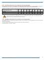
2.2.2 Water composition
Dissolved substances in the water can cause corrosion in the heat exchangers.
It is mandatory to make sure the parameters of the water comply with the following table:
Description Values
Total hardness 2,0 ÷ 6,0 °f
1.2 ÷ 3.4 °d
Langelier index - 0,4 ÷ 0,4
pH 7,5 ÷ 8,5
Electrical conductivity 10÷500 µS/cm
Organic elements -
Hydrogen carbonate (HCO3-) 70 ÷ 300 ppm
Sulphates (SO42-) < 50 ppm
Hydrogen carbonate / Sulphates (HCO3-/SO42-) > 1
Chlorides (Cl-) < 50 ppm
Nitrates (NO3-) < 50 ppm
Hydrogen sulphide (H2S) < 0,05 ppm
Ammonia (NH3) < 0,05 ppm
Sulphites (SO3), free chlorine (Cl2) < 1 ppm
Carbon dioxide (CO2) < 5 ppm
Metal cations < 0,2 ppm
Manganese ions (Mn++) < 0,2 ppm
Iron ions (Fe2+, Fe3+) < 0,2 ppm
Iron + Manganese < 0,4 ppm
Phosphates (PO43-) < 2 ppm
Oxygen < 0,1 ppm
ppm = mg/l
The use of water with values above the limits stated in the table will immediately void the warranty.
It is mandatory to include a system for eliminating possible organic substances in the water that could pass through the lter
and settle in the heat exchangers, which would lead to malfunctioning and/or breakage over time.
The use of water containing organic substances will immediately void the warranty.

13
We reserve the right to make changes without any prior notice. Translation from original instructions
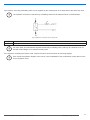
2.2.3 Minimum water content in the system
For correct operation of the unit, it is necessary to ensure a buering on the system such as to comply with the minimum
operating time considering the greater between the minimum OFF time and the minimum ON time.
In short, these contribute to limiting the number of times the compressors are switched on per hour and to preventing un-
desired deviations from the set point of the delivered water temperature.
The following experimental formula allows the minimum water volume of the system to be calculated:
where
v = Minimum water content of the system [ l ]
Ρtot = Total refrigeration capacity [kW]
N = N° of capacity reduction steps
Δτ = Time interval – the greater between minimum OFF time and minimum ON time [s]
ΔΤ = Allowed dierential on the water temperature [°C](unless specied, this is 2.5°C)
ρ = Water density 1000 [kg / ³]
Сp = Specic heat of water 4.186 [kJ / (kg°C)]
Fm = Q factor: experimental factor, dierent from 1 for some types of unit
K1 = Experimental multiplying constant depending on the type of compressor
With some terms grouped together, the formula can be rewritten as follows:
If the carrying uid consists of mixtures of water-glycol (ethylene or propylene), the density and specic heat values must
consequently be adjusted.
For units with scroll compressor, the constants used in the formula assume the following values:
K [l/kW] 17,2
N
For units without inverter = the number of compressors installed in the unit
For units with single-compressor inverter = 3
For units with a dual-compressor inverter (1 inverter cmp + 1 on/o cmp) = 6
For units with a three-compressor inverter (1 inverter cmp + 2 on/o cmp) = 9
Fm 1
K1 0,25
The constant K considers that the maximum between the minimum ON and OFF time is Δτ=180s.
Larger amounts of water are in any case always preferable, because they allow a smaller number of stops and starts of
the compressors, less wear of them and an increase in the eciency of the system as a consequence of a reduction in the
number of transients.

14 We reserve the right to make changes without any prior notice.Translation from original instructions
2.2.4 Installing the ow switch
The installed ow switch is provided with a 1” male connector.
The unit must be installed following the arrow that shows the direction of ow.
The ow switch supplied with the unit is not a suitable device for operation in a danger zone. The tter shall
carry out a ammability assessment and a classication of the danger zone at the site of installation, as
required by standard EN378-3.
The installation must be done in a straight section of pipe away from lters, valves, etc. at a distance of at least 5 times the
pipe diameter, both upline and downline.
The ow switch is factory calibrated for installation on a horizontal pipe.
The push rod must be in the vertical position.
The connections of the ow switch with the terminal board in the electrical control panel must be made using the common
terminal and the terminal that is normally open when there is no water circulation.
Check the terminals provided for the ow switch in the wiring diagram of the unit.
Use a 2 x 1 mm² cable or at most a 2 x 1.5 mm² cable, with diameter between 6 and 9 mm, suitable for installation.
Lock the cable in place with cable ties in the section between the ow switch and the inlet to the electrical control panel.
Refer to the instructions provided with the ow switch to identify the correct set of foils.
Correct ow switch/sensor operation requires that the speed of the uid owing through them is within the
specied operating limits.
The table below shows the pipe diameters to be used in the system section where the ow switch is to be installed, accor-
ding to the ow rate.
Hydraulic diameter Min. ow rate Max. ow rate
(inches) m3/h m3/h
1" 2,5 3,6
1" 1/4 3,6 6,1
1" 1/2 6,1 9,2
2" 9,2 15,0
2" 1/2 15,0 24,0
3" 24,0 36,0
4" 36,0 60,0
5" 60,0 94,0
6" 94,0 120,0
8" 120,0 240,0
10" 240,0 381,6
The ow switch must be installed at the outlet on the exchanger that produces cold water and therefore, depending on the
unit, care must be taken to install it in the correct circuit.
The Manufacturer declines any and all responsibility for malfunctions due to non-complying installation of the
ow switch.
On all units, except for the “OH” and “HP” versions, connect the ow switch to the outlet of the user-side
exchanger, indicated in the dimensional diagram and with the relevant plate on the unit.
On “HP” version units, where cold can be produced on two exchangers, connect the ow switch to the outlet
of the user-side exchanger and to the outlet of the source-side exchanger, indicated in the dimensional dia-
gram and with the relevant plates on the unit.

15
We reserve the right to make changes without any prior notice. Translation from original instructions
2.2.5 Operation with water to the evaporator at low temperature
With temperatures below 5°C, it is mandatory to work with water and anti-freeze mixtures, and also change the safety devi-
ces (anti-freeze, etc.), which must be carried out by qualied authorised personnel or by the manufacturer.
The glycol percentage by weight is determined based on the desired temperature of the chilled water (see table).
Minimum ambient temperature or liquid
outlet temperature (°C) 0 -5 -10 -15 -20 -25 -30 -35 -40
Freezing point (°C) -5 -10 -15 -20 -25 -30 -35 -40 -45
Antifreeze % by weight
Ethylene glycol 6 22 30 36 41 46 50 53 56
Propylene glycol 15 25 33 39 44 48 51 54 57
If ambient temperatures are expected to be lower than the freezing point of water, it is essential to use an-
ti-freeze mixtures in the above-mentioned percentages.
2.2.6 Operation with water to the condenser at low temperature
The standard units are not designed to operate with water to the condenser at too low a temperature (refer to the Technical
Catalogue for the limits).
In order to operate below this limit, the unit could require structural modications.
If required, please contact our company.

16 We reserve the right to make changes without any prior notice.Translation from original instructions
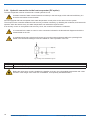
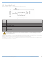
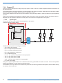
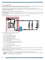
2.2.7 Condensation control at the source hydraulic circuit
The temperature and ow rate of the source circuit water must be maintained within the operating limits stated in the Tech-
nical Catalogue.
It is essential for the water to come in at the connection indicated in the dimensional diagram and with the
relevant plate on the unit.
A modulating three-way valve that will ensure an incoming water temperature within the operating limits
stated in the Technical Catalogue must be installed for correct operation of the unit.
Fig. 2 3-way valve installation layout
02 Condenser
EL Motor-driven pump
V3 Thermostatic three-way valve
The three-way modulating valve can be supplied as accessory by the manufacturer.
As accessory, the signal to control it can also be supplied with the modulating valve.
The servo control supplied with the unit is not a suitable device for operation in a danger zone. The tter
shall carry out a ammability assessment and a classication of the danger zone at the site of installation, as
required by standard EN378-3.
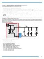
The hydraulic connection of the three-way modulating valve must be made as shown in the illustration.
Fig. 3 Hydraulic connection of three-way valve
02 Condenser
EL Motor-driven pump
V3 Three-way valve

17
We reserve the right to make changes without any prior notice. Translation from original instructions
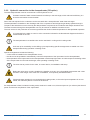
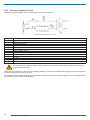
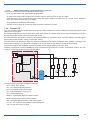
As accessory, a two-way modulating valve can be supplied by the manufacturer as an alternative to the three-way valve.
The hydraulic connection of the two-way modulating valve must be made as shown in the illustration.
Fig. 4 Hydraulic connection of two-way valve
02 Condenser
V2 Two-way valve
For some sizes, the manufacturer supplies a three-way modulating valve, with way "B" closed or to be clo-
sed with a blind ange, to be used as two-way valve.
If the signal for controlling the valve is used, connect the servo control as shown in the wiring diagram.
Also consult the hydraulic diagram of the unit for correct installation of the condensation control device in the
source hydraulic circuit.

18 We reserve the right to make changes without any prior notice.Translation from original instructions
2.2.8 Hydraulic connection to the heat recuperator (DC option)
The heat recuperator must be connected to a closed hydraulic circuit.
Constant renewal of water causes limescale to build up in the exchanger, which reduces its eciency in a
short time and makes it unserviceable.
All units equipped with heat recuperator have water temperature control probe on the return from the system.
The microprocessor controller enables the heat recovery unit when necessary, by disabling the condenser, and restores its
operation when the heat recovery unit water temperature has reached the required value.
If an anomaly occurs on the hydraulic heat recovery circuit, the controller will restart the condenser.
It is essential for the water to come in at the connection indicated in the dimensional diagram and with the
relevant label on the unit.
A modulating three-way valve that will ensure an incoming water temperature within the operating limits
stated in the Technical Catalogue must be installed for correct operation of the unit.
Fig. 5 3-way valve installation layout
02 Heat recuperator
EL Motor-driven pump
V3 Thermostatic three-way valve
Before the valve servo control is installed, the installer must carry out a ammability assessment and a clas-
sication of the danger zone at the site of installation, as required by standard EN378-3.

19
We reserve the right to make changes without any prior notice. Translation from original instructions
2.2.9 Hydraulic connection to the desuperheater (DS option)
The heat desuperheater must be connected to a closed hydraulic circuit.
Constant renewal of water causes limescale to build up in the exchanger, which reduces its eciency in a
short time and makes it unserviceable.
Part of the heat rejected in the condenser can be recovered with a “desuperheater” water heat exchanger.
The desuperheater is installed on the discharge side of the compressors and refrigerant gas always passes through it.
The part of the heat that is not recovered by the desuperheater is rejected in the condenser that always remains active.
The heat recovered through the desuperheater can only be used as an addition to another source.
The main source for the production of heat must guarantee the minimum water temperature for desuperheater operation.
It is essential for the water to come in at the connection indicated in the dimensional diagram and with the
relevant label on the unit.
The desuperheater in reversible units can be used both in cooling and in heating mode.
Units set up for reversibility on the chilling cycle require taking specic arrangements to enable use of the
desuperheater during operation in heating mode.
Specic arrangements include the following:
- a valve must be installed in the desuperheater circuit;
- the valve must be operated to automatically control the temperature of the input water into the desuperheater;
- the temperature of the input water into the desuperheater must be kept higher than 10 K with respect to the design value
of the output water from the heat exchanger, when operating in heating mode.
The client has to provide for the valve, its control device, its installation and setup.
Before the valve servo control is installed, the installer must carry out a ammability assessment and a clas-
sication of the danger zone at the site of installation, as required by standard EN378-3.
If desuperheater operation is not required during heating mode, or where the input temperature is not con-
trolled, the relevant hydraulic circuit must be shut o.
If a desuperheater is tted, included in heating mode, whether it is used or not, it has an impact on (i.e. reduces) the thermal
power and the max. temperature of the output water.

20 We reserve the right to make changes without any prior notice.Translation from original instructions
2.2.10 Refrigerant leak detector
A refrigerant leak detector with an IR sensor is installed on the units.
This device is designed to immediately detect any refrigerant leakage. When 10% LFL is exceeded, the detector enables
ventilation in the technical compartment and ventilation in the electrical panel (where it is not enabled yet); additionally, it
switches on the red light on the door of the electrical panel, it closes the alarm potential free contact, and nally it cuts out
power to the electrical panel by means of a specic circuit breaker, excepting the side where the detector power connectors
are located.
Calibration and testing are required by the manufacturer (see “Periodic checks” chapter).
The alarm contact opens for a few seconds any time power to the sensor is cut out and then restored. Set a
suitable delay in the warning message. It takes the sensor a few minutes to complete the start cycle, during
which the fault contact stays open.
The detector must be tested and/or calibrated by a qualied technician.
To test and calibrate the device, qualied operators must know the rules and regulations laid down by the industrial sector
and/or by the country of installation.
In any case, the sensing element of the device has a lifetime after which it must be replaced. Refer to the “Periodic checks”
chapter.
As for the method and methods of testing, calibration and replacement of the device, refer to the authorized service center.
For replacement of the sensing device and for other accessories needed for calibration, refer to your custo-
mer service centre.
Upon rst start-up, a check must be made of the value read by the sensor and the sensor must be calibrated
where necessary.
Page is loading ...
Page is loading ...
Page is loading ...
Page is loading ...
Page is loading ...
Page is loading ...
Page is loading ...
Page is loading ...
Page is loading ...
Page is loading ...
Page is loading ...
Page is loading ...
Page is loading ...
Page is loading ...
Page is loading ...
Page is loading ...
Page is loading ...
Page is loading ...
Page is loading ...
Page is loading ...
Page is loading ...
Page is loading ...
Page is loading ...
Page is loading ...
Page is loading ...
Page is loading ...
Page is loading ...
Page is loading ...
Page is loading ...
Page is loading ...
Page is loading ...
Page is loading ...
Page is loading ...
Page is loading ...
Page is loading ...
Page is loading ...
Page is loading ...
Page is loading ...
Page is loading ...
Page is loading ...
Page is loading ...
Page is loading ...
Page is loading ...
Page is loading ...
Page is loading ...
Page is loading ...
Page is loading ...
Page is loading ...
Page is loading ...
Page is loading ...
Page is loading ...
Page is loading ...
Page is loading ...
Page is loading ...
Page is loading ...
Page is loading ...
-
 1
1
-
 2
2
-
 3
3
-
 4
4
-
 5
5
-
 6
6
-
 7
7
-
 8
8
-
 9
9
-
 10
10
-
 11
11
-
 12
12
-
 13
13
-
 14
14
-
 15
15
-
 16
16
-
 17
17
-
 18
18
-
 19
19
-
 20
20
-
 21
21
-
 22
22
-
 23
23
-
 24
24
-
 25
25
-
 26
26
-
 27
27
-
 28
28
-
 29
29
-
 30
30
-
 31
31
-
 32
32
-
 33
33
-
 34
34
-
 35
35
-
 36
36
-
 37
37
-
 38
38
-
 39
39
-
 40
40
-
 41
41
-
 42
42
-
 43
43
-
 44
44
-
 45
45
-
 46
46
-
 47
47
-
 48
48
-
 49
49
-
 50
50
-
 51
51
-
 52
52
-
 53
53
-
 54
54
-
 55
55
-
 56
56
-
 57
57
-
 58
58
-
 59
59
-
 60
60
-
 61
61
-
 62
62
-
 63
63
-
 64
64
-
 65
65
-
 66
66
-
 67
67
-
 68
68
-
 69
69
-
 70
70
-
 71
71
-
 72
72
-
 73
73
-
 74
74
-
 75
75
-
 76
76


Western Sigma Sky OH / Hi OH / HPW R7 Installation and Operating Instructions
- Category
- Heat pumps
- Type
- Installation and Operating Instructions
- This manual is also suitable for
Ask a question and I''ll find the answer in the document
Finding information in a document is now easier with AI
Related papers
-
Western TETRIS-W REV Installation and Operating Instructions
-
-
-
-
-
-
-
-
-
Other documents
-
BITZER Application guide for the use of R744 Datasheet
-
Carrier 30XBZE Installation guide
-
GGM Gastro TMK520L Owner's manual
-
-
Calorex IPT22 ALX Owners & Installation Manual
-
Lochinvar Amicus LAHP1402WW Installation, Commissioning, User And Maintenance Instructions
-
Toolots DC-3006 User manual
-
Swegon TEAL Owner's manual
-
AIREDALE TurboChill Water Cooled User manual
-
Hamworthy Tyneham heat pump 26-32 kW Installation guide