Western PRO-FLO 2 (Serial numbers 202389 - 202649) Owner's manual
- Category
- Spreader
- Type
- Owner's manual

January 15, 2017
Lit. No. 13721, Rev. 08
This manual is for WESTERN® PRO-FLO 2 Spreaders with serial numbers
beginning with 202389–202649.
Western Products, PO Box 245038, Milwaukee, WI 53224‑9538 • www.westernplows.com
PRO‑FLO™ 2 Tailgate Spreader
Owner's Manual
Original Instructions
This manual supersedes all editions with an earlier date.
CAUTION
Read this document before operating
or servicing the spreader.


Lit. No. 13721, Rev. 08 3 January 15, 2017
TABLE OF CONTENTS
PREFACE ....................................................................4
Owner's Information Form .................................... 4
SAFETY ...................................................................... 5
Safety Denitions .................................................. 5
Warning/Caution Labels .......................................5
Under-Frame Mount Assembly Labels ................. 5
Serial Number Label .............................................6
Safety Precautions ................................................6
Fuses ....................................................................7
Personal Safety..................................................... 7
Fire and Explosion ................................................ 7
Cell Phones ...........................................................7
Ventilation .............................................................8
Battery Safety ....................................................... 8
Noise ..................................................................... 8
Vibration ................................................................8
Torque Chart ......................................................... 8
LOADING .................................................................... 9
Certication ...........................................................9
Material Weights ...................................................9
MOUNTING THE SPREADER ................................. 10
In-Bed Mount ...................................................... 10
Under-Frame Mount ............................................ 11
OPERATING THE SPREADER ................................ 13
Driving and Spreading on Snow and Ice ............ 13
Adjusting Feed Gate and Deector ..................... 14
Deector Effect ................................................ 14
PWM Control ...................................................... 15
Single Speed Control .......................................... 16
REMOVING THE SPREADER ................................. 17
In-Bed Mount ...................................................... 17
Under-Frame Mount ............................................ 18
RECEIVER HITCH .................................................... 19
Safety .................................................................. 19
Important Information About Towing ................... 19
Ball Mounts/Drawbars ......................................... 19
Hitch Balls ........................................................... 19
Trailer Couplers ................................................... 19
Safety Chains ...................................................... 19
Electrical Connections ........................................ 19
Sway Controls .....................................................20
Other Useful Equipment ...................................... 20
Tire Ination ........................................................20
Equipment and Parts Check ...............................20
No Passengers in Trailers! .................................. 20
Trailer Loading .................................................... 20
Vehicle ................................................................20
Driving ................................................................. 20
Excessive Sway .................................................. 20
Controlling Trailer Sway ......................................20
MAINTENANCE ........................................................ 21
Belt Tension ........................................................ 21
After Each Use .................................................... 21
At the End of Each Season
(or Extended Storage) .....................................22
Fuse Replacement .............................................. 22
Recycle ...............................................................22
Gear Oil Specication ......................................... 22
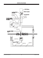
WIRING DIAGRAM ..................................................23
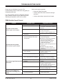
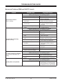
TROUBLESHOOTING GUIDE ................................. 24
PWM Control ......................................................24
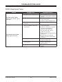
Single Speed Control .......................................... 25
Mechanical Problems ......................................... 26

Lit. No. 13721, Rev. 08 4 January 15, 2017
PREFACE
This manual has been prepared to acquaint you with
the safety information, operation and maintenance of
your new tailgate spreader. Please read this manual
carefully and follow all recommendations. This will
help ensure protable and trouble-free operation of
your spreader. Keep this manual accessible. It is a
handy reference in case minor service is required.
When service is necessary, bring your spreader to
your distributor. They know your spreader best and are
interested in your complete satisfaction.
NOTE: This spreader is designed to spread snow
and ice control materials only. Do not use it
for purposes other than those specied in this
manual.
Register your spreader online at www.westernplows.com
OWNER'S INFORMATION
Owner's Name: ______________________________________________________________________
Date Purchased: _____________________________________________________________________
Outlet Name: ______________________________________________ Phone: _________________
Outlet Address: ______________________________________________________________________
Vehicle Model: _______________________________________________ Year: _______________
Spreader Type (Model): ________________________________ Serial #: ______________________
Length: ________________________ Weight: __________________ lb/kg: _________________

Lit. No. 13721, Rev. 08 5 January 15, 2017
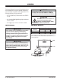
SAFETY
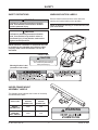
UNDER‑FRAME MOUNT
ASSEMBLY LABELS
The diagram below indicates the location of the safety
and identication labels.
HITCH TYPE
MAX. GROSS
TRAILER
WEIGHT (LB)
MAX.
TONGUE
WEIGHT (LB)
WEIGHT
DISTRIBUTING 10000 1000
WEIGHT
CARRYING
BALL AMOUNT
10000 1000
67181
67182
WARNING
Caution Label
67272
CAUTION
Do not lift spreader by wire channel.
This could cause product damage
and/or personal injury.
Warning/Caution Label
(located on both sides)
SAFETY DEFINITIONS
NOTE: Indicates a situation or action that can lead
to damage to your spreader and vehicle or other
property. Other useful information can also be
described.
WARNING/CAUTION LABELS
Become familiar with and inform users about the
warning and caution labels on the spreader.
NOTE: If labels are missing or cannot be read, see
your sales outlet.
CAUTION
Indicates a potentially hazardous situation
that, if not avoided, may result in minor or
moderate injury. It may also be used to alert
against unsafe practices.
WARNING
Indicates a potentially hazardous situation
that, if not avoided, could result in death or
serious personal injury.

Lit. No. 13721, Rev. 08 6 January 15, 2017
SAFETY
SAFETY PRECAUTIONS
Improper installation and operation could cause
personal injury and/or equipment and property
damage. Read and understand labels and the
Owner's Manual before installing, operating, or
making adjustments.
WARNING
• Driver to keep bystanders minimum of
25 feet away from operating spreader.
• Before working with the spreader, secure all
loose-tting clothing and unrestrained hair.
• Before operating the spreader, verify that all
safety guards are in place.
• Before servicing the spreader, wait for
conveyor, auger, and spinner to stop.
• Do not climb into or ride on spreader.
WARNING
Do not install the control for this product in
the deployment path of an air bag. Refer to
vehicle manufacturer's manual for air bag
deployment area(s).
CAUTION
If rear directional, CHMSL light, or brake
stoplights are obstructed by the spreader, the
lights shall be relocated, or auxiliary directional
or brake stoplights shall be installed.
WARNING
Overloading could result in an
accident or damage. Do not exceed
GVWR or GAWR ratings as found
on the driver‑side vehicle door
cornerpost. See Loading section to determine
maximum volumes of spreading material.
Code Denition
YY 2-Digit Year
MM 2-Digit Month
DD 2-Digit Day
LL 2-Digit Location Code
XXXX 4-Digit Sequential Number
ZZZZZZ 5- to 7-Digit Assembly PN
SERIAL NUMBER LABEL

Lit. No. 13721, Rev. 08 7 January 15, 2017
SAFETY
CAUTION
Disconnect electric and/or hydraulic power
and tag out if required before servicing or
performing maintenance.
NOTE: Lubricate grease ttings after each use.
Use a good quality multipurpose grease.
FUSES
The electrical system contains several blade-style
automotive fuses. If a problem should occur and
fuse replacement is necessary, the replacement
fuse must be of the same type and amperage rating
as the original. Installing a fuse with a higher rating
can damage the system and could start a re. Fuse
Replacement, including fuse ratings and locations, is
located in the Maintenance section of this Owner's
Manual.
PERSONAL SAFETY
• Remove ignition key and put the vehicle in park or
in gear to prevent others from starting the vehicle
during installation or service.
• Wear only snug-tting clothing while working on
your vehicle or spreader.
• Do not wear jewelry or a necktie, and secure long
hair.
• Wear safety goggles to protect your eyes from
battery acid, gasoline, dirt, and dust.
• Avoid touching hot surfaces such as the engine,
radiator, hoses, and exhaust pipes.
• Always have a re extinguisher rated BC handy,
for ammable liquids and electrical res.
FIRE AND EXPLOSION
Be careful when using gasoline. Do not use gasoline
to clean parts. Store only in approved containers away
from sources of heat or ame.
CELL PHONES
A driver's rst responsibility is the safe operation of
the vehicle. The most important thing you can do
to prevent a crash is to avoid distractions and pay
attention to the road. Wait until it is safe to operate
Mobile Communication Equipment such as cell phones,
text messaging devices, pagers or two-way radios.
CAUTION
DO NOT leave unused material in
hopper. Material can freeze or solidify,
causing unit to not work properly.
Empty and clean after each use.
WARNING
Gasoline is highly ammable and gasoline
vapor is explosive. Never smoke while
working on vehicle. Keep all open ames
away from gasoline tank and lines. Wipe up
any spilled gasoline immediately.
CAUTION
• Do not operate a spreader in need of
maintenance.
• Before operating the spreader, reassemble
any parts or hardware removed for cleaning
or adjusting.
• Before operating the spreader, remove
materials such as cleaning rags, brushes,
and hand tools from the spreader.
• Before operating the spreader, read the
engine owner's manual, if so equipped.
• While operating the spreader, use auxiliary
warning lights, except when prohibited by law.
• Tighten all fasteners according to the
Torque Chart. Refer to Torque Chart for the
recommended torque values.

Lit. No. 13721, Rev. 08 8 January 15, 2017
SAFETY
VENTILATION
BATTERY SAFETY
NOISE
Airborne noise emission during use is below 70 dB(A)
for the spreader operator.
VIBRATION
Operating spreader vibration does not exceed 2.5 m/s2
to the hand-arm or 0.5 m/s2 to the whole body.
TORQUE CHART
1/4-20 10
91
54
1/4-28 12
11
71
5/16-1
81
50 212
5/16-2
41
70 240
3/8-16 269 376
3/8-24 29
74
20
7/16-1442
96
06
7/16-20
9/16-12
9/16-18
5/8-11
5/8-18
3/4-10
3/4-16
7/8-9
7/8-14 47
46
69
64
49
091-8
1-12 70
49
95
1/2-13
1/2-20
11.9
13.7
24.6
27.3
43.6
26.9
53.3
93
148
49.4
69.8
77.9
106.4
120.0
8.4
9.7
17.4
19.2
30.8
35.0
49.4
55.2
75.3
85.0
M6 x 1.00
M12 x 1.75
M8 x 1.25
M14 x 2.00
M10 x 1.50
M27 x 3.00
M22 x 2.50
M30 x 3.50
M24 x 3.00
M20 x 2.5011.1
19.5
38.5
67
107
7.7
613
778
1139
1545
450
428
562
796
1117
M33 x 3.50
M36 x 4.00
2101
2701
1468
1952
325
M16 x 2.00 231167
M18 x 2.50 318222
Recommended Fastener Torque Chart
Size Size
Torque (ft-lb)
Grade
5
Grade
8
Metric Fasteners Class 8.8 and 10.9
These torque values apply to fasteners
except those noted in the instructions.
Torque (ft-lb)
Grade
5
Grade
8
Size Size
Torque (ft-lb)
Class
8.8
Class
10.9
Torque (ft-lb)
Class
8.8
Class
10.9
Inch Fasteners Grade 5 and Grade 8
CAUTION
Batteries normally produce explosive gases
which can cause personal injury. Therefore,
do not allow ames, sparks, or lit tobacco
to come near the battery. When charging or
working near a battery, always cover your
face and protect your eyes, and also provide
ventilation.
• Batteries contain sulfuric acid, which burns
skin, eyes, and clothing.
• Disconnect the battery before removing or
replacing any electrical components.
CAUTION
Read instructions before assembling.
Fasteners should be nger tight until
instructed to tighten according to the Torque
Chart. Use standard methods and practices
when attaching spreader, including proper
personal protective safety equipment.
WARNING
Vehicle exhaust contains lethal fumes.
Breathing these fumes, even in low
concentrations, can cause death. Never
operate a vehicle in an enclosed area without
venting exhaust to the outside.

Lit. No. 13721, Rev. 08 9 January 15, 2017
LOADING
10 ft³
3.9 ft³
This Owner's Manual covers vehicles that have been
recommended for carrying the spreader. Please see
your local dealer for proper vehicle applications. The
following vehicles are recommended:
• All Ford Light Duty F-Series trucks over 6000 lb
GVWR.
• All Chevrolet/GMC Light Duty pickup trucks over
6000 lb GVWR.
• All Dodge pickup trucks over 5800 lb GVWR.
CERTIFICATION
WARNING
Overloading could result in an accident or
damage. Do not exceed GVWR or GAWR as
found on the driver‑side cornerpost of vehicle.
WARNING
New untitled vehicle installation of a spreader
requires National Highway Trafc Safety
Administration altered vehicle certication
labeling. Installer to verify that struck load of
snow or ice control material does not exceed
GVWR or GAWR rating label and complies
with FMVSS.
CAUTION
Read and adhere to manufacturer's
ice‑control material package
labeling, including Material Safety
Data Sheet requirements.
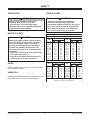
MATERIAL WEIGHTS
Density
Material (lb/ft3)(lb/yd3)(kg/m3)
Salt 80 2160 1282
Sand 100 2700 1602
Material densities are approximate and are based on dry,
loose material. It is the responsibility of the operator to
know the weight of the material to be spread and the vehicle
carrying capacity.
WARNING
The use of under‑frame or in‑bed mounts on
half‑ton trucks is restricted to spreading only
salt or calcium chloride. (Max. 80 lb per cu ft.)
Failure to comply could result in exceeding
the payload capacity.

Lit. No. 13721, Rev. 08 10 January 15, 2017
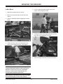
MOUNTING THE SPREADER
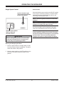
In‑Bed Mount
1. Remove the tailgate from the vehicle.
2. Place the mount assembly into the bed of the
vehicle.
3. Slide the assembly forward engaging the locator
studs.
4. Secure the front of the mount assembly to the
channel using hold-down bolts. Hand tighten.
NOTE: Pay special attention when drilling or
clamping dissimilar metals to aluminum bodies.
Galvanic corrosion can occur if not handled
properly. Contact vehicle manufacturer for
recommended attachment practices.
NOTE: Apply a small amount of grease to the bolt
thread periodically to ensure easy removal.
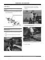
5. Lift the hopper assembly using a hoist or two
people, and tip slightly forward.
6. Position the tabs of the hopper assembly over the
top of the mount assembly, and lower.
7. Allow the hopper assembly to lower into position.
Locator
Studs
Mount
Assembly
Hold‑down
Bolt
Tab

Lit. No. 13721, Rev. 08 11 January 15, 2017
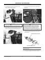
8. Insert hold-down pins and secure with hairpin
cotter pins.
9. Connect the spreader wiring harness to the
vehicle wiring harness.
10. Verify vehicle stoplights and spreader center high
mounted stoplight are working properly.
NOTE: Grease all electrical connections with
dielectric grease.
MOUNTING THE SPREADER
Spreader Wiring Harness
Vehicle Wiring Harness
CAUTION
Both hold‑down pins must be in place and
secured with hairpin cotter pins. The hopper
assembly may become unstable if the pins
are not properly secure while the vehicle is in
motion. Never use a nger to check alignment.
Hold‑down Pin
Hairpin Cotter Pin
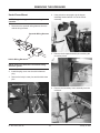
Under‑Frame Mount
1. Install the secondary frame into the subframe.
2. Insert the hitch pin on each side, and secure with
linchpins.
CAUTION
Visually check Hitch Pin holes before
assembly. Never use a nger to check
alignment.
Secondary
Frame Subframe
Hitch Pin

Lit. No. 13721, Rev. 08 12 January 15, 2017
MOUNTING THE SPREADER
5. Insert pin on each side and secure with hairpin
cotter pin.
6. Connect spreader wiring harness to the vehicle
wiring harness.
NOTE: Grease all electrical connections with
dielectric grease.
7. Verify proper stoplight and spreader operation.
3. Lift the hopper assembly using a hoist or two
people, and tip slightly forward.
4. Position tabs on the hopper assembly over the top
of the mount assembly, and lower the assembly.
Spreader Wiring Harness
Vehicle Wiring Harness
CAUTION
Both hold‑down pins must be in place and
secured with hairpin cotter pins. The hopper
assembly may become unstable if the pins
are not properly secure while the vehicle is in
motion. Never use a nger to check alignment.
CAUTION
Visually align tabs into the secondary frame.
Hold‑down Pin
Hairpin Cotter Pin

Lit. No. 13721, Rev. 08 13 January 15, 2017
Driving and Spreading on Snow and Ice
Follow your vehicle owner's manual instructions for
driving in snow and ice conditions. Remember when
you drive on snow or ice, your wheels will not get good
traction. You cannot accelerate as quickly, turning
is more difcult and you will need longer braking
distance. Wet and hard packed snow or ice offers the
worst tire traction. It is very easy to lose control. You
will have difculty accelerating. If you do get moving,
you may have poor steering and difcult braking which
can cause you to slide out of control.
OPERATING THE SPREADER
WARNING
Never operate equipment when under the
inuence of alcohol, drugs, or medications that
might alter your judgment and/or reaction time.
WARNING
Never exceed 45 mph (72 km/h) when loaded
spreader is attached to vehicle. Braking
distances may be increased and handling
characteristics may be impaired at speeds
above 45 mph (72 km/h).
WARNING
Never allow children to operate or climb on
equipment.
Here are some tips for driving in these conditions:
• Drive defensively.
• Do not drink, then drive or spread snow and ice
control materials.
• Spread or drive only when you have good visibility
for operating a vehicle.
• If you cannot see well due to snow or icy
conditions, you will need to slow down and keep
more space between you and other vehicles.
• Slow down, especially on higher speed roads.
Your headlamps can light up only so much road
ahead.
• If you are tired, pull off in a safe place and rest.
• The spreader's size and location reduce driver
visibility to the rear of the vehicle. We recommend
an OSHA compliant backup alarm for all governed
employers.
• Keep your windshield and all glass on your vehicle
clean to see around you.
• Dress properly for the weather. Wear layers of
clothing; as you get warm, you can take off layers.

Lit. No. 13721, Rev. 08 14 January 15, 2017
OPERATING THE SPREADER
Adjusting Feed Gate and Deector
Spread pattern, pattern width, and the amount of
material dispensed are dependent on the spinner
speed, feed gate position, and deector position.
Deector Effect
WARNING
Before making any adjustments to the gate/
deector settings, turn the spreader off. Wait
for all conveyor, auger, and spinner movement
to stop.

Lit. No. 13721, Rev. 08 15 January 15, 2017
There are two control options: the PWM Control and
the Single Speed Control.
PWM Control
Starting and Stopping the Motor
1. To start the spreader motor, press the power
switch to the START/BLAST position and release.
This is a momentary position and the power
switch will automatically return to the ON position
when released. The spreader will operate at the
speed selected on the speed dial.
2. Press the power switch to the OFF position to stop
the motor. The power switch will remain in this
position.
NOTE: The truck ignition must be on to start the
spreader.
NOTE: If the truck ignition is turned off while the
spreader is running, the motor will stop.
OPERATING THE SPREADER
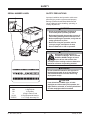
Power Switch
(Used to start and
stop the spinner.)
Speed Dial
(Used to change the
speed of the spinner.)
Indicator Lights
(Indicate whether the spinner is in motion.
Left light is red and indicates a fault.
Right light is green and indicates power is on.)
WARNING
Before starting the spreader, the driver shall
verify that all bystanders are a minimum of
25 feet away from operating spreader.
Adjusting the Spinner Speed
The speed setting can be adjusted when the spreader
is either on or off.
1. Turn the speed dial clockwise. The speed will
increase as the numbers on the speed dial
increase.
2. Turning the speed dial counterclockwise will
decrease the speed.
Blast/Maximum Speed
1. Press and hold the power switch in the
START/BLAST position as long as maximum
speed is needed.
NOTE: If speed dial is set to max, pressing blast
button will not affect spinner speed.
2. Release the power switch when maximum speed
is no longer needed. The switch automatically
returns to the ON position and the speed shown
on the speed dial.
NOTE: When blast is used, the speed dial does
not move to the maximum speed setting, but
remains at the preset speed.
Spinner Indicator Lights
Two lights on the cab control indicate the status of the
motor:
• Left light is red and indicates a fault. When the red
(left) light is on, the power is on and the motor is
not running.
• Right light is green and indicates power is on.
When the green (right) light is on, there is power to
the control and the motor is running.
If there are problems while operating the spreader,
refer to the Troubleshooting section of this manual.
NOTE: Always place the cover on the hopper to
prevent moisture buildup. Do not let the spreader
sit idle with material in the hopper for an extended
period of time. This can cause the material to
compact and reduce or stop the ow of material.

Lit. No. 13721, Rev. 08 16 January 15, 2017
OPERATING THE SPREADER
Single Speed Control
Starting and Stopping the Motor
1. Move the power switch to the ON position to start
the motor. Motor will start immediately. The power
switch will remain in this position.
2. Move the power switch to the OFF position to stop
the motor. The power switch will remain in this
position.
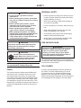
BLAST
ON
OFF
SPINNER
Spinner Indicator Light
(Illuminated light indicates
power to the motor.)
ON/OFF Control Switch
(Used to start and
stop the spinner.)
Blast Position
Move and hold the power switch to the BLAST position
for as long as momentary operation is needed. When
released, the switch will automatically return to the
OFF position and stop the motor.
NOTE: The truck ignition must be on to start the
spreader.
NOTE: If the truck ignition is turned off while the
spreader is running, the motor will stop.
If there are problems while operating the spreader,
refer to the Troubleshooting section in this manual.
NOTE: Always place the cover on the hopper to
prevent moisture buildup. Do not let the spreader
sit idle with material in the hopper for an extended
period of time. This can cause the material to
compact and reduce or stop the ow of material.
WARNING
Before starting the spreader, the driver shall
verify that all bystanders are a minimum of
25 feet away from operating spreader.

Lit. No. 13721, Rev. 08 17 January 15, 2017
In‑Bed Mount
NOTE: Empty the hopper before removing the
spreader.
1. Disconnect the spreader wiring harness from the
vehicle wiring harness.
NOTE: Grease the electrical connections using
dielectric grease.
2. Install the plug cover over the vehicle harness
plug.
3. Remove the hairpin cotter pins and hold-down
pins.
REMOVING THE SPREADER
Spreader Wiring Harness
V
ehicle Wiring Harness
4. Using a hoist or two people, tip the hopper
assembly forward and lift it off of the mount
assembly.
5. Loosen and remove the hold-down bolts from the
front of the mount assembly.
6. Remove the mount assembly from the vehicle.
7. Install the tailgate.
Hold‑down Pin
Hairpin Cotter Pin
Hold‑down
Bolt

Lit. No. 13721, Rev. 08 18 January 15, 2017
REMOVING THE SPREADER
4. Using a hoist or two people, tip the hopper
assembly forward and lift it off of the mount
assembly.
5. Remove the linchpins and hitch pins retaining the
secondary frame.
6. Remove the secondary frame assembly from the
subframe.
Under‑Frame Mount
NOTE: Empty the hopper before removing the
spreader.
1. Disconnect the spreader wiring harness from the
vehicle wiring harness.
NOTE: Grease the electrical connections using
dielectric grease.
2. Install the plug cover over the vehicle harness
plug.
3. Remove the hairpin cotter pins and the hold-down
pins.
Spreader Wiring Harness
Vehicle Wiring Harness
Hold‑down Pin
Hairpin Cotter Pin
Secondary
Frame Subframe
Hitch Pin

Lit. No. 13721, Rev. 08 19 January 15, 2017
RECEIVER HITCH
Safety
Important Information About Towing
Make sure all operators of your equipment read
and understand this information before towing. This
information will help you properly select, use, and
maintain your towing equipment. Learn the capabilities
and limitations of each part.
Gross trailer weight is the weight of the trailer plus
the weight of the cargo. Measure gross trailer weight
by putting the fully loaded trailer on a vehicle scale.
Tongue weight is measured by placing the fully loaded
trailer on a level surface with the coupler at normal
towing height. Use a commercial scale to measure the
weight at the coupler.
Ball Mounts/Drawbars
Select these products by their gross trailer weight and
tongue weight ratings. Select hitches and receivers
for specic vehicles. Do not purchase a ball mount
or drawbar which will give more than a 4" drop or
7" extension as measured from the lower rear edge of
the receiver.
Hitch Balls
Select by gross trailer weight rating, coupler socket
size, and mounting platform thickness and hole size.
Hole must not exceed threaded shank diameter by
more than 1/16". Use lock washer. Tighten according
to instructions. When tightened, shank must protrude
beyond bottom of nut. Gross trailer weight rating and
ball diameter are marked on balls.
Trailer Couplers
The coupler socket should be smooth, clean and
lightly lubricated. Tighten or adjust according to the
coupler manufacturer's instructions.
Safety Chains
Connect safety chains properly every time you tow.
Cross chains under coupler. Attach securely to the
hitch or tow vehicle so they cannot bounce loose.
Leave only enough slack to permit full turning. Too
much slack may prevent chains from maintaining
control if other connections separate. Do not allow
chains to drag along the road.
Electrical Connections
Make these safety-critical connections every time you
tow, no matter how short the trip. Check operation,
including electric brake manual control, before getting
on the road.
WARNING
• Do not overload any part of your towing
system.
• Do not modify your hitch. Install only
on specied vehicles which are in good
condition.
• This product is designed to tow trailers.
Do not use as cargo carriers, motorcycle
carriers, boat hoists, or coupler alignment
devices. Do not use as a jacking point. Do
not attach anything with or in place of the
ball.
• Do not pull multiple trailers. Towing one
trailer behind another may cause severe
instability and loss of control.
CAUTION
Never exceed the gross trailer weight or tongue
weight of this equipment. Never exceed the
lowest weight rating of any part of your towing
system. See the Under‑Frame Mount Assembly
Labels area in the Safety section of this
manual.

Lit. No. 13721, Rev. 08 20 January 15, 2017
Sway Controls
Sway controls can lessen the effects of sudden
maneuvers, wind gusts, and buffeting caused by other
vehicles. We recommend sway controls for trailers
with large surface areas, such as travel trailers.
Adjustable friction models can help control the sway of
travel trailers with low tongue weight percentages.
Other Useful Equipment
Air springs, air shocks, or helper springs are useful for
some hitch applications. A transmission cooler may
be necessary for heavy towing. Many states require
towing mirrors on both sides.
Tire Ination
Check often. Follow tow vehicle and trailer
manufacturer's recommendations. Improper tire
ination can cause trailer sway.
Equipment and Parts Check
Check ball, coupler, chains, retaining pins and clips,
and all other connections every time you tow. Re-
check at fuel and rest stops.
No Passengers in Trailers!
Under no circumstances should people be allowed in
trailers while towing.
Trailer Loading
Proper loading helps prevent sway. Place heavy
objects on the oor ahead of the axle. Balance the
load side to side and secure it to prevent shifting.
Tongue weight should be 10–15% of gross weight for
most trailers. Too low a percentage of tongue weight
can cause sway. Never load the trailer rear-heavy;
load the trailer front heavy.
Vehicle
The spreader operating vehicle shall be maintained
according to the manufacturer's recommendations.
Driving
The additional weight of a trailer affects acceleration,
braking, and handling. Allow extra time for passing,
stopping, and changing lanes. Severe bumps can
damage your towing vehicle, hitch, and trailer. Drive
slowly on rough roads. Stop and make a thorough
inspection if any part of your towing system strikes the
road. Correct any problems before resuming travel.
Excessive Sway
Excessive sway can lead to loss of control. Sway
motion should settle out quickly. Sway tends to
increase on a downgrade. Starting slowly, increase
the speed in gradual steps. If sway occurs, reduce
speed slowly, stop, and adjust your trailer load and
equipment. Repeat until the trailer is stable at highway
speed. Do this whenever your trailer loading changes.
Controlling Trailer Sway
Turbulence from another vehicle, a wind gust, or a
downgrade can cause sudden sway along with shift
of the trailer's load or a trailer tire blowout. If the
trailer sways, it is the driver's responsibility to assess
the situation and take appropriate action. Below are
the suggestions that may apply when assessing the
situation. If your trailer starts to sway:
• Reduce your speed gradually.
• Hold steering wheel as steady as possible.
• If your trailer has electric brakes, apply the trailer
brakes alone without using the tow vehicle's
brakes.
• Do not hit your brake pedal hard unless absolutely
necessary.
• Do not try to steer out of the sway condition.
Sudden or violent steering can worsen the sway.
• Do not speed up or swaying will increase.
• Do not continue towing a trailer that tends to sway
or you may lose control.
RECEIVER HITCH
Page is loading ...
Page is loading ...
Page is loading ...
Page is loading ...
Page is loading ...
Page is loading ...
Page is loading ...
Page is loading ...
-
 1
1
-
 2
2
-
 3
3
-
 4
4
-
 5
5
-
 6
6
-
 7
7
-
 8
8
-
 9
9
-
 10
10
-
 11
11
-
 12
12
-
 13
13
-
 14
14
-
 15
15
-
 16
16
-
 17
17
-
 18
18
-
 19
19
-
 20
20
-
 21
21
-
 22
22
-
 23
23
-
 24
24
-
 25
25
-
 26
26
-
 27
27
-
 28
28


Western PRO-FLO 2 (Serial numbers 202389 - 202649) Owner's manual
- Category
- Spreader
- Type
- Owner's manual
Ask a question and I''ll find the answer in the document
Finding information in a document is now easier with AI
Related papers
-
Western Utility Mount Kit #75922 Installation guide
-
-
-
-
-
-
-
-
-
Other documents
-
 SnowEx SR-210 Owner's Manual and Installation Instructions
-
 SnowEx Bulk Pro SP-1575 Owner's Manual and Installation Instructions
-
 Boss Snowplow TGS 600 Owner's manual
-
 SnowEx SP-1575-1 Owner's manual
-
 SnowEx V-Maxx G2 VX-6010 Installation Instructions Manual
-
Brinly-Hardy SDZ-80 User guide
-
Ventrac SS575 Owner's manual
-
-
CURT 17200 User manual
-
 SnowEx V-Maxx G2 VX-2200HO Installation Instructions Manual


