Page is loading ...

1812-482-2932
Installation
Instructions
Recommended Tools
www.ridetech.com
Front Components:
11013011 Front ShockWaves
11012899 Front Lower StrongArms
11013699 Front Upper StrongArms
11019100 Front Sway Bar
Rear Components:
11027199/11037199 Rear 4Link System
24340701 Rear ShockWaves
1955-1957 Chevy Car ShockWave
Installation Instructions
Table of contents
Pages 2-6............... Front ShockWaves
Pages 7-11.............. Front Lower StrongArms
Pages 12-15............. Front Upper StrongArms
Pages 16-20............. Front Sway Bar
Pages 21-32............. Rear 4-Link
Pages 33-34............. Rear ShockWaves
Pages 35.................. Notes and Care of ShockWaves
Pages 36-37............. Shock Adjustment
1955-1957 GM B-Body TQ ShockWave Kit
11020398 or 11030398
REV6 6/14/22

2
www.ridetech.com
Installation
Instructions
Recommended Tools
www.ridetech.com
Table of contents
Page 3.......... Included components
Page 4-5....... ShockWave Installation
Page 6.......... Notes and Care of Your ShockWave
ShockWave Dimensions:
Center of bearing to Center of bearing:
Compressed: 11.00”
Ride Height: 13.10”
Extended: 14.50”
THE DELRIN BALL REQUIRES A 3/4” HOLE FOR THE FLANGE TO
GO THROUGH. THIS CAN BE DRILLED WITH A UNIBIT.
Part # 11013011 - 55-57 GM B-Body Front TQ Series ShockWave
1000 Series Bellow, 2.00” Stud/Eye 4.1” Shock
Installation Instructions

3812-482-2932
Installation
Instructions
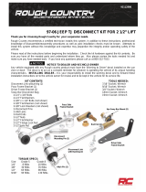
Major Components .....In the box
Item # Part # Description QTY
1 986-10-071 4.1” Stroke TQ Series Shock 2
2 90009988 2.00” Stud Top (Installed on Shock) - Includes Adjuster Knob & Screw 2
3 24090199 1000 Series 6.5” Double Convoluted AirSpring 2
4 234-00-153 AirSpring Locking Ring (Installed on shock) 2
99055000 Locking Ring Set Screw (Installed on shock) 2
7 90002312 2.00” Aluminum Stud Top Base 2
8 90001904 Bottom Delrin Ball 2
9 90001903 Top Delrin Ball 2
10 90001902 Delrin Ball Aluminum Top Cap 2
11 99562003 9/16”-18 Thin Nylok Nut 2
12 210-35-120-0 Adjuster Knob - (90009988 assembly) 2
90009969 #4-40 X 1/4” SS, 18-8 Pan Head Torx Cap - (90009988 assembly) 2
70012160 2.00” Stud Top Metering Rod (installed in stud top) 2
15 90001994 5/8” ID Bearing (installed in shock and eyelet) 4
16 90001995 Bearing Snap Ring (installed in shock and eyelet) 8
17 026-05-000 Reservoir Mount 4
18 99050000 Reservoir Mounting Screw - 5mm SS X .5 SHCS 12
19 99952006 Spring Washer 2
20 90009908 High Speed Adjsuter Knob 2
21 90009907 Low Speed Adjsuter Knob 2
22 99041000 4 -40 X .500 Button head socket cap screw 2
23 85000003 Hex Wrench for Reservoir Mounting Screws 1
12
11
10
1
2
15
7
18
20
9
21
8
19
22
17
3
23
4
16
WARNING: ATTEMPTING TO REMOVE THE AIR FITTING WILL DAMAGE IT AND VOID THE
WARRANTY.

4
www.ridetech.com
Installation
Instructions
ShockWave Installation
1. Remove the OEM bushing flange by prying
it out of the frame hole. After removing the
flange, drill the OEM shock hole out to 3/4”.
This can be done with a Unibit.
2. Trim the coil spring location ring flush to
prevent the ring from hitting the top of the
ShockWave Air Spring. A die grinder with a
cutoff wheels works well here.
3. To allow clearance for the Shockwave,
some trimming must be done on the outside
edge of the coil spring pocket as shown by
the white line in the picture. This is best done
with either a cut off wheel or plasma cutter.
Grind all cuts smooth when finished.
Note: It may be helpful to go ahead and install
the lower StrongArms and Shockwaves to
determine exactly what needs to be removed.
2.
1.
3.
REMOVE FLANGE
&
DRILL TO 3/4”
TRIM FLANGE FLUSH

5812-482-2932
Installation
Instructions
ShockWave Installation
Note: The airline must also be routed at this
time. It can be ran through the subframe to-
ward the rear of the vehicle.
4. The air fitting location can be rotated by
twisting the bellow assembly separate of the
shock. Place the Shockwave into the coil spring
pocket with the stud sticking through the OEM
shock hole. See assembly Diagram 4. OEM
Shock hole must be drilled out to ¾”
1. Stud top aluminum base
2. Delrin ball lower half
3. Delrin ball upper half
4. Aluminum cap
5. 9/16” SAE Nylok jam nut
6. Threaded stud (screwed onto shock shaft)
7. Rebound adjusting knob
8. Screw
5. Raise the lower arm up to the Shockwave
and bolt them together using the 1/2” x 3 ¼”
bolt and Nylok supplied w/ the lower arms. An
aluminum spacer will be on each side of the
bearing. Torque to 75 ftbs.
6. Raise the lower control arm to full compres-
sion and double-check to make sure the Shock-
wave does not rub on anything at anytime. Al-
lowing the Shockwave to rub on anything will
cause failure and is not a warrantable situation.
7. The best ride quality will occur around 50-
60% suspension travel; depending on vehicle
weight this typically occurs around 85-100 psi.
4.
5.
1. Stud top aluminum base
2. Delrin ball lower half
3. Delrin ball upper half
4. Aluminum cap
5. 9/16” SAE Nylok jam nut
6. Threaded stud (screwed onto shock
shaft)
7. Rebound adjusting knob
8. Screw

6
www.ridetech.com
Installation
Instructions
Notes and Care of your Shockwaves
The care and feeding of your new ShockWaves
1. Although the ShockWave has an internal bumpstop, DO NOT DRIVE THE VEHICLE DEFLATED
RESTING ON THIS BUMPSTOP. DAMAGE WILL RESULT. The internal bumpstop will be damaged, the
shock bushings will be damaged, and the vehicle shock mounting points may be damaged to the point of
failure. This is a non warrantable situation.
2. Do not drive the vehicle overinflated or “topped out”. Over a period of time the shock valving will
be damaged, possibly to the point of failure. This is a non warrantable situation! If you need to raise your
vehicle higher that the ShockWave allows, you will need a longer unit.
3. The ShockWave is designed to give a great ride quality and to raise and lower the vehicle. IT IS NOT
MADE TO HOP OR JUMP! If you want to hop or jump, hydraulics are a better choice. This abuse will result
in bent piston rods, broken shock mounts, and destroyed bushings. This is a non warrantable situation.
4. Do not let the ShockWave bellows rub on anything. Failure will result. This is a non warrantable
situation.
5. The ShockWave product has been field tested on numerous vehicles as well as subjected to many
different stress tests to ensure that there are no leakage or durability problems. Failures have been nearly
nonexistent unless abused as described above. If the Shockwave units are installed properly and are not
abused, they will last many, many years. ShockWave units that are returned with broken mounts, bent
piston rods, destroyed bumpstops or bushings, or abrasions on the bellows will not be warrantied.
NOTES:
WARNING: ATTEMPTING TO REMOVE THE AIR FITTING WILL DAMAGE IT AND VOID THE
WARRANTY.
TIGHTENING THE TOP 9/16”-18 NUT: SNUG THE NUT DOWN AGAINST THE TOP CAP. YOU NEED TO BE
ABLE TO ARTICULATE THE SHOCK BY HAND. WE TORQUE THE NUT TO 80 INLBS USING A 7/8” CROWS
FOOT WRENCH ON A TORQUE WRENCH.
You can clock the airfitting location on the ShockWave by turning the AirSpring assembly of the shock.
Make sure the fitting doesn’t contact the frame.
When cutting the airline, use a razor blade. The cut needs to be a clean cut and square for the airline to
seal properly.
The Locking ring on the shock is NOT adjustable. These rings are set at the
factory to optimize the AirSpring stroke with the shock stroke.

7812-482-2932
Installation
Instructions
Recommended Tools
www.ridetech.com
Table of contents
Page 8......... Lower Control Arm Components
Page 9......... Getting Started & Installation
Page 10....... StrongArm Installation
Page 11....... Installing Spindle and Alignment
1955-1957 GM B-Body Front Lower ShockWave/CoilOver StrongArms
1955-1957 GM B-Body Lower StrongArms
Installation Instructions
Part # 11012899
REV2 10/30/20

8
www.ridetech.com
Installation
Instructions
1
2
5
5
555
346
3
4
6
7
9
8
10
Upper Control Arm Components .....In the box
Driver Side Shown
Item
#Part Number Description QTY
1 90001294 Driver Lower Control Arm (Shown) 1
1 90001295 Passenger Lower Control Arm 1
2 90000916 kit Lower Ball Joint Kit - Proforged # 101-10080 2
3 90001442 Delrin Bushing 4
4 90001289 Delrin Bushing Inner Sleeve 4
5 90002694 Lower Cross Shaft Kit 1 pr
6 99433001 Outer Washer - Cross Shaft 4
7 90002062 Shock Bearing Spacers 4
8 99501005 1/2”-13 x 3 1/2” Hex Bolt GR8 2
9 99503014 1/2” SAE Flat Washer 4
10 99502009 1/2”-13 Nylok Nut 2

9812-482-2932
Installation
Instructions
Getting Started.........
Congratulations on your purchase of the Ridetech Tri5 StrongArms. These StrongArms have been designed
to give your Tri5 excellent handling along with a lifetime of enjoyment. Some of the key features of the
StrongArms: Ball joint angles have been optimized for the lowered ride height, Delrin bushings are used
to eliminate bushing deflection along with providing free suspension movement through the entire travel.
The Delrin bushings are made from a material that is self lubricating so no grease zerks are needed.
When assembling the Control Arms, tighten the cross shaft bolts enough to create
drag on the delrin bushings, the arm should still move through its travel by hand.
Installation
1. Remove the lower control arms from the car. If you are replacing the upper control arms and spindle,
remove them too. Refer to a Factory Service Manual for the proper method.
2. 2. Insert the Ball Joint into the Control Arm
from the bottom side with the Stud pointing
downward. Insert the supplied Bolts from the
top side. Install a Lock Washer and Hex Nut on
the threads of each bolt. Torque the hardware
to 25 ftlbs.
3. Install the supplied 7/16” Lock Washers &
7/16” Flat Washers on each of the (4) 7/16”-
20 x 1 1/2” Bolts supplied in the kit. Thread
each Bolt/Washer setup into the end of the
Cross Shaft of the Lower Control Arm. Do not
tighten until the control arms are installed on
the car.
3.
1
3
2

10
www.ridetech.com
Installation
Instructions
Installing StrongArm
4. The Lower Control Arm is attaching the
frame using factory hardware. The driver side
arm is shown in Figure “2”. The sway bar
mount is located to the front of the car.
Install the ShockWaves/CoilOvers
at this time. Refer to the Shock-
Waves/CoilOvers instructions for
Assembly.
5. The Lower Control Arm is attaching the
frame using factory hardware. The driver side
arm is shown in Figure “3”.
6. Bolt the Shockwave or CoilOver to the
lower arm using the supplied 1/2” x 3 1/2”
bolt, 1/2” flat washers, and 1/2” nylok nut.
Insert the supplied aluminum spacers in each
side of the shock bearing and slip it into the
control arm. Line the spacers/bearing up with
the 1/2” hole in the shock straps of the control
arm and install hardware. Torque the hardware
to 75 ftlbs.
4.
5.
6.
Driver Side
Top View

11 812-482-2932
Installation
Instructions
8. Tighten all fasteners. Connect the sway bar linkage to the new StrongArms. If you are going to install
the Ridetech MuscleBar, now is a good time to do it.
When assembling the Control Arms, tighten the cross shaft bolts enough to create
drag on the delrin bushings, the arm should still move through its travel by hand.
Suggested Alignment Specs:
Camber: Street: -.5 degrees
Caster: Street: +3.0 to + 5.0 degrees
Toe: Street: 1/16” to 1/8” toe in
Installing Spindle and Alignment
7. Attach the Spindle to the control arms.
Torque Specs:
Ball joint - 45 ftlbs and tighten to line up cotter
pin.
Install the Cotter Pin after tightening the ball
joint nut.
INSTALL THE GREASE ZERK IN THE BALL
JOINT AND GREASE THE BALL JOINT AFTER
ASSEMBLY.
7.

12
www.ridetech.com
Installation
Instructions
Recommended Tools
www.ridetech.com
Table of contents
Page 13......... Upper Control Arm Components
Page 14......... Getting Started & Installation
Page 15......... Installing Spindle and Alignment
Part # 11013699 - 1955-1957 GM B-Body Front Upper StrongArms
1955-1957 GM B-Body Upper StrongArms
Installation Instructions
REV2 10/30/20

13 812-482-2932
Installation
Instructions
1
2
345
6
7
4
5
6
7
88
Upper Control Arm Components .....In the box
Driver Side Shown
Item
#Part Number Description QTY
1 90001292 Driver Upper Control Arm (Shown) 1
1 90001293 Passenger Upper Control Arm 1
2 90003041 kit Tall Upper Ball Joint Kit - Proforged # 101-10477 2
3 90002695 kit Cross Shaft Kit - contains 2 cross shafts 1
4 90001442 Delrin Bushing 4
5 90001288 Delrin Bushing Inner Sleeve 4
6 99373001 Outer Washer - Cross Shaft 4
7 99373005 3/8” Split Lock Washer -Cross Shaft 4
8 99371015 3/8”-24 x 1 1/2” Hex Bolt - Cross Shaft 4

14
www.ridetech.com
Installation
Instructions
Getting Started.........
Congratulations on your purchase of the Ridetech Tri5 StrongArms. These StrongArms have been designed
to give your Tri5 excellent handling along with a lifetime of enjoyment. Some of the key features of the
StrongArms: Ball joint angles have been optimized for the lowered ride height, Delrin bushings are used
to eliminate bushing deflection along with providing free suspension movement through the entire travel.
The Delrin bushings are made from a material that is self lubricating so no grease zerks are needed.
When assembling the Control Arms tighten the cross shaft bolts enough to create
drag on the delrin bushings, the arm should still move through its travel by hand.
Installation
1. Remove the upper control arms from the car. Keep the shims separate so that you can put them back
in the location they were removed from. If you are replacing the lower control arms and spindle, remove
them too. Refer to a Factory Service Manual for the proper method.
2. 2. Insert the Ball Joint into the Control Arm
from the TOP side with the Stud pointing
downward. Insert the supplied Bolts from the
bottom side. Install a Lock Washer and Hex
Nut on the threads of each bolt. Torque the
hardware to 18 ftlbs.
3. The Upper Control Arm is attached to the
factory frame using factory hardware. The
driver side arm is shown in Figure “3”. The
Ball joint is located on the arm to the REAR of
the car.
3.
Driver Side
Top View

15 812-482-2932
Installation
Instructions
Installing Spindle and Alignment
4. The Upper Control Arm is attaching
the factory mount using factory hardware.
Reinstall the shims in the location they were
removed from. The passenger side arm is
shown in Figure “4”.
5. Attach the Spindle to the control arms.
These control arms use a tall ball joint, the boot
will NOT touch the spindle. This is normal.
Torque Specs:
Ball joint - 45 ftlbs and tighten to line up cotter
pin.
Install the Cotter Pin after tightening the ball
joint nut.
5.
6. Tighten all fasteners.
When assembling the Control Arms tighten the cross shaft bolts enough to create
drag on the delrin bushings, the arm should still move through its travel by hand.
Suggested Alignment Specs:
Camber: Street: -.5 degrees
Caster: Street: +3.0 to + 5.0 degrees
Toe: Street: 1/16” to 1/8” toe in
DUE TO THE SHANK OF THE BALL JOINT BEING LONGER, THE BALL JOINT BOOT IS DESIGNED
TO SEAL ON THE BALL JOINT SHANK. IT DOES NOT SEAL AGAINST THE SPINDLE.
4.

16
www.ridetech.com
Installation
Instructions
Recommended Tools
www.ridetech.com
Table of contents
Page 17......... Included Components and Hardware List
Page 18......... Sway Bar Installation
Page 19......... Frame Mount Installation
Page 20......... Frame Mount and PosiLink Installation
Part # 11019100 - 1955-1957 B-Body Front Sway Bar
1955-1957 GM B-Body Front Sway Bar
Installation Instructions
Install all Front Suspension Components before installing the Sway Bar.
REV1 6/14/22

17 812-482-2932
Installation
Instructions
Major Components .....In the box
Part # Description QTY
90000731 Front Sway Bar 1
90001100 Bushing & Strap Kit 2
90000729 Sway Bar Bushing Frame Plate 2
90000717 Aluminum Step Washer - Control Arm 4
90000924 10mm Straight PosiLink - PosiLink Assembly 2
90000926 10mm 90 Degree PosiLink - PosiLink Assembly 2
99115001 10mm x 1.5” Thread Stud - PosiLink Assembly 2
90001092 Tube of Lithium Grease 1
1.
Part # Description Usage QTY
99371005 3/8”-16 x 1 1/4” Hex Bolt Bushing Mount & Bushing to Frame 8
99373003 3/8” Flat washer End link & Bushing Mounts 18
99372002 3/8”-16 Nylok Nut End link & Bushing Mounts 8
99115006 M10 Lock Washer PosiLink to Sway Bar 2
99112002 M10-1.5 Nylok Nut PosiLink to Control Arm 2
Getting Started.........
Install all front suspension components before installing the sway bar.
The Tri5 didn’t come equipped with a swaybar. This kit contains the mounts needed to add a
swaybar to your Tri5. If your car already has a swaybar, it will need to be removed.
1. Apply lithium grease to the poly bushing.
Install the bushing over the sway bar.
Hardware Kit .....99010047

18
www.ridetech.com
Installation
Instructions
FRONT
DRILL
REMOVE RIVET
FRONT
Sway Bar Installation
2. Install bushing straps over the poly sway
bar bushings.
1955-1956 FRAME MOUNT INSTALLATION
3. The rivet shown in Diagram “3” will need
to be removed. This hole will be use to locate
the sway bar frame mount.
4. Diagram “4” shows the mounting plate
installed on the driver side. Use a 3/8” flat
washer on a 3/8”x 1 1/4” hex bolt to attach
the frame plate to the frame. Insert the bolt
into the rivet hole with the plate positioned as
it is in Diagram “5”. With the bolt inserted
into the rivet hole, use a 3/8” flat washer and
3/8” nylok nut to snug it down. Align the
mounting plate parallel with the outside of the
frame rail and drill the rear 2 holes through the
frame. Insert a second 3/8” hex bolt and 3/8”
flat washer into the rear hole with a 3/8” Flat
washer and 3/8” nylok nut to tighten. Repeat
process on other side and tighten hardware.
The rear inner hole will be used later.
3.
2.
4.

19 812-482-2932
Installation
Instructions
Frame Mount Installation
5. Install 3/8” flat washers on (2) 3/8” x 1 1/4”
hex bolts. Install them through the top side of
the of the remaining holes in each mounting
plate with the threads pointing down. The rear
bolt will also go through the frame rail.
6. With the bushings and straps installed on
the sway bar, put the swaybar in position on
the 3/8” bolts. Attach it using 3/8” flat washers
and 3/8” nylok nuts. Do NOT completely
tighten the hardware. It will be left partially
loose until the PosiLinks are installed.
1957 FRAME MOUNT INSTALLATION
7. There isn’t a rivet to use as a locator on the
1957 frame. The frame mount is position 5”
from the FRONT of the frame rail to the FRONT
EDGE of the frame mount. The center of the
bolt hole is 1 1/2” from the outside edge of
the frame. Use the frame mount as a template
to drill the 2 holes. The hardware will need to
installed from the top with the threads pointing
down. Use a 3/8” x 1 1/4” hex bolt with a flat
washer in each one. Do this for both sides.
With the hardware installed, install a frame
mount on the hardware with the SMALL bolt
pattern to the inside of the car. Tighten down
with a 3/8” flat washer and 3/8” nylok nut
6.
5.
7.
5”

20
www.ridetech.com
Installation
Instructions
Frame Mount & End Link Installation
8. Install 3/8” flat washers on (2) 3/8” x 1 1/4”
hex bolts and install them through the top side
of the of the remaining holes in each mounting
plate with the threads pointing down. With
the bushings and straps installed on the sway
bar, put the sway bar in position on the 3/8”
bolts. Attach it using 3/8” flat washers and
3/8” nylok nuts. Do NOT completely tighten
the hardware. It will be left partially loose until
the PosiLinks are installed.
9. Bolt the 90 degree end of the PosiLink to
the sway bar. A 3/8” flat washer and 10mm
lock washer must be installed between the
PosiLink and the bar.
10. Bolt the straight end of the PosiLink to the
lower control arm. An aluminum step washer
must be installed on each side of the control
arm tab. Fasten with a 10mm Nylok nut. Then
tighten the bushing frame bolts.
9.
8.
10.
/