21 / 36
Azimut-/Elevationstabelle (Azimuth/elevation table)
Multifeed-Anwendung 3°-Orbitabstand (Multi-feed application 3° orbital spacing)
Multifeed-Anwendung 6°-Orbitabstand (Multi-feed application 6° orbital spacing)
Seite/page 21-28
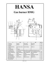
Multifeed-Anwendung 3°-Orbitabstand (Multi-feed application 3° orbital spacing)
Tabelle für Winkel V (Table for angle V)
Satellit (Satellite)
ASTRA/Eutelsat
W2 19,2°/16,0°
Eutelsat W2/
Hotbird 16°/13°
Hotbird/Eutel-
sat W2A 13°/10°
Eutelsat W2A/
W3A 10°/7°
Antlantik Bird 3/2
-5,0°/-8,0°
Deutschland (Germany)
Bad Reichenhall
Breite (Latit.):
47,72°
-4,2° -1,4° 1,3° 4,0° 16,5°
Länge (Longit.):
12,90°
Berlin
Breite (Latit.):
52,50°
-3,2° -0,8° 1,5° 3,7° 14,4°
Länge (Longit.):
13,42°
Bremen
Breite (Latit.):
53,07°
-6,5° -4,2° -2,0° 0,2° 11,1°
Länge (Longit.):
8,83°
Cottbus
Breite (Latit.):
51,75°
-2,6° -0,1° 2,2° 4,5° 15,4°
Länge (Longit.):
14,33°
Dortmund
Breite (Latit.):
51,50°
-7,9° -5,5° -3,2° -0,8° 10,7°
Länge (Longit.):
7,47°
Dresden
Breite (Latit.):
51,05°
-3,1° -0,6° 1,8° 4,2° 15,3°
Länge (Longit.):
13,73°
Emden
Breite (Latit.):
53,35°
-7,6° -5,3° -3,2° -1,0° 9,9°
Länge (Longit.):
7,20°
Erfurt
Breite (Latit.):
50,97°
-5,3° -2,8° -0,4° 2,0° 13,5°
Länge (Longit.):
11,03°
Flensburg
Breite (Latit.):
54,78°
-5,7° -3,5° -1,4° 0,7° 10,8°
Länge (Longit.):
9,45°
Frankfurt/Main
Breite (Latit.):
50,12°
-7,3° -4,8° -2,3° 0,1° 12,2°
Länge (Longit.):
8,68°
Freiburg/Brsg.
Breite (Latit.):
48,00°
-8,6° -5,9° -3,3° -0,6° 12,4°
Länge (Longit.):
7,83°
Greifswald
Breite (Latit.):
54,08°
-3,0° -0,8° 1,3° 3,5° 13,6°
Länge (Longit.):
13,38°
Hamburg
Breite (Latit.):
53,55°
-5,5° -3,3° -1,1° 1,1° 11,7°
Länge (Longit.):
9,98°
Hannover
Breite (Latit.):
52,37°
-5,9° -3,6° -1,3° 1,0° 12,0°
Länge (Longit.):
9,77°
Kassel
Breite (Latit.):
51,30°
-6,4° -4,0° -1,6° 0,7° 12,2°
Länge (Longit.):
9,43°
Kiel
Breite (Latit.):
54,32°
-5,3° -3,1° -1,0° 1,2° 11,5°
Länge (Longit.):
10,13°
Koblenz
Breite (Latit.):
50,33°
-8,2° -5,7° -3,3° -0,8° 11,2°
Länge (Longit.):
7,50°
Leipzig
Breite (Latit.):
51,30°
-4,1° -1,7° 0,7° 3,1° 14,3°
Länge (Longit.):
12,37°
Magdeburg
Breite (Latit.):
52,12°
-4,6° -2,2° 0,1° 2,4° 13,4°
Länge (Longit.):
11,63°
Mönchengladbach
Breite (Latit.):
51,18°
-8,7° -6,4° -4,0° -1,6° 10,1°
Länge (Longit.):
6,45°
München
Breite (Latit.):
48,13°
-5,3° -2,6° 0,1° 2,7° 15,3°
Länge (Longit.):
11,57°
Neubrandenburg
Breite (Latit.):
53,55°
-3,2° -0,9° 1,3° 3,5° 13,8°
Länge (Longit.):
13,25°
Nürnberg
Breite (Latit.):
49,45°
-5,5° -2,9° -0,4° 2,2° 14,2°
Länge (Longit.):
11,05°
Osnabrück
Breite (Latit.):
52,28°
-7,2° -4,9° -2,6° -0,3° 10,9°
Länge (Longit.):
8,05°
Seite/page 29-36