E6581279⑦
- 12 -
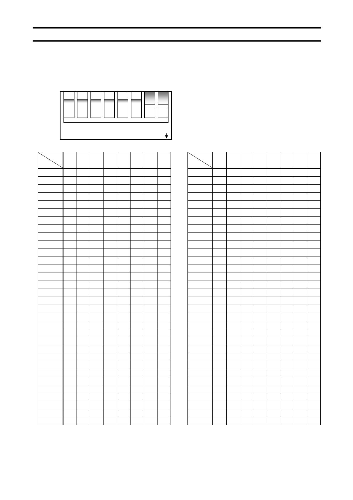
4.2. Setting a station address
The DIP switch on the circuit board of the option is used to set a station address. Each
DIP switch is ON when it is flipped to the lower position. By default, it is
factory-configured to 2.
The station address must be unique and not match any other device on the network.
SW
ID 1 2 3 4 5 6 7 8 SW
ID 1 2 3 4 5 6 7 8
0 OFF OFF OFF OFF OFF OFF OFF OFF 32 OFF OFF ON OFF OFF OFF OFF OFF
1 OFF OFF OFF OFF OFF OFF OFF ON 33 OFF OFF ON OFF OFF OFF OFF ON
2 OFF OFF OFF OFF OFF OFF ON OFF 34 OFF OFF ON OFF OFF OFF ON OFF
3 OFF OFF OFF OFF OFF OFF ON ON 35 OFF OFF ON OFF OFF OFF ON ON
4 OFF OFF OFF OFF OFF ON OFF OFF 36 OFF OFF ON OFF OFF ON OFF OFF
5 OFF OFF OFF OFF OFF ON OFF ON 37 OFF OFF ON OFF OFF ON OFF ON
6 OFF OFF OFF OFF OFF ON ON OFF 38 OFF OFF ON OFF OFF ON ON OFF
7 OFF OFF OFF OFF OFF ON ON ON 39 OFF OFF ON OFF OFF ON ON ON
8 OFF OFF OFF OFF ON OFF OFF OFF 40 OFF OFF ON OFF ON OFF OFF OFF
9 OFF OFF OFF OFF ON OFF OFF ON 41 OFF OFF ON OFF ON OFF OFF ON
10 OFF OFF OFF OFF ON OFF ON OFF 42 OFF OFF ON OFF ON OFF ON OFF
11 OFF OFF OFF OFF ON OFF ON ON 43 OFF OFF ON OFF ON OFF ON ON
12 OFF OFF OFF OFF ON ON OFF OFF 44 OFF OFF ON OFF ON ON OFF OFF
13 OFF OFF OFF OFF ON ON OFF ON 45 OFF OFF ON OFF ON ON OFF ON
14 OFF OFF OFF OFF ON ON ON OFF 46 OFF OFF ON OFF ON ON ON OFF
15 OFF OFF OFF OFF ON ON ON ON 47 OFF OFF ON OFF ON ON ON ON
16 OFF OFF OFF ON OFF OFF OFF OFF 48 OFF OFF ON ON OFF OFF OFF OFF
17 OFF OFF OFF ON OFF OFF OFF ON 49 OFF OFF ON ON OFF OFF OFF ON
18 OFF OFF OFF ON OFF OFF ON OFF 50 OFF OFF ON ON OFF OFF ON OFF
19 OFF OFF OFF ON OFF OFF ON ON 51 OFF OFF ON ON OFF OFF ON ON
20 OFF OFF OFF ON OFF ON OFF OFF 52 OFF OFF ON ON OFF ON OFF OFF
21 OFF OFF OFF ON OFF ON OFF ON 53 OFF OFF ON ON OFF ON OFF ON
22 OFF OFF OFF ON OFF ON ON OFF 54 OFF OFF ON ON OFF ON ON OFF
23 OFF OFF OFF ON OFF ON ON ON 55 OFF OFF ON ON OFF ON ON ON
24 OFF OFF OFF ON ON OFF OFF OFF 56 OFF OFF ON ON ON OFF OFF OFF
25 OFF OFF OFF ON ON OFF OFF ON 57 OFF OFF ON ON ON OFF OFF ON
26 OFF OFF OFF ON ON OFF ON OFF 58 OFF OFF ON ON ON OFF ON OFF
27 OFF OFF OFF ON ON OFF ON ON 59 OFF OFF ON ON ON OFF ON ON
28 OFF OFF OFF ON ON ON OFF OFF 60 OFF OFF ON ON ON ON OFF OFF
29 OFF OFF OFF ON ON ON OFF ON 61 OFF OFF ON ON ON ON OFF ON
30 OFF OFF OFF ON ON ON ON OFF 62 OFF OFF ON ON ON ON ON OFF
31 OFF OFF OFF ON ON ON ON ON 63 OFF OFF ON ON ON ON ON ON
1 2 3 4 5 6 7 8
DIP ON


