
E6581364②
TOSVERT VF-AS1/PS1
Commercial Power Supply Backup and
Commercial Power Supply/Inverter Switching
Instruction Manual
Technical information described in this document is used to explain typical operations and
applications of products, and this is not intended to grant warranty or licensing right on its
use regarding TOSHIBA group or a third party intellectual property and other right.

E6581364
1
- Contents -
1. Commercial Power Supply Backup..................................................................................... 2
1.1. Standard connection diagram...................................................................................................... 2
1.1.1. Switching circuit connection diagram, Time chart, Parameter settings .................................... 3
1.2. Standard connection diagram (Star-delta switching start) ........................................................... 4
1.2.1. Switching circuit connection diagram, Time chart, Parameter settings .................................... 5
1.3. Precautions ................................................................................................................................. 6
2. Commercial Power Supply/Inverter Switching .................................................................... 7
2.1. Standard connection diagram...................................................................................................... 7
2.1.1. Switching circuit connection diagram, Time chart, Parameter settings .................................... 8
2.2. Precautions ................................................................................................................................. 9

E6581364
2
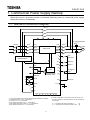
1. Commercial Power Supply Backup
When the inverter’s protective function is activated, switching power to commercial power supply
makes the motor run immediately.
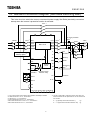
1.1. Standard connection diagram
*1: The control power supply backup option (Model: CPS002Z) is needed.
*2: Observe the Item 1 in 1.3, “Precautions.”
*3: See Item 2 in 1.3, “Precautions.”
*4: Be careful about Items 3 in 1.3, “Precautions.”
*5:
Be careful about Items 5 and 7 in 1.3, “Precautions.”
*6: Be careful about Item 6 in 1.3, “Precautions.
MC1
*2
For motor protection
THR
*4
Motor
FL
G / E
F
RES
CC
R/L1
S/L2
T/L3
U/T1
V/T2
W/T3
FLC
FLB
FLA
Run
command
S1
ST
R
S2
S3
OUT2
P24/PLC
OUT1
RY2
PO
PB
PC/-
PA/+
Main circuit
Stand-by
*7
Reset
*6
Emergency
stop
*5
CCA
RX
VI/II
RR/S4
PP
A
M
FM
OUT1
MCCB
Common
I M
RY1
Protective action
detection
relay
MC3
*2
MC2
*3
+SU
Control
circuit
Control power supply
backup option
*1
NO
CC
*7: VF-AS1's 'WP1/WN1' model and VF-PS1 don't have 'ST'
terminal. Please set next parameter for use 'S3' terminal as
'ST' function.
f110 (Always ON function selection 1) = 0
f117 (Input terminal function selection: S3) = 6

E6581364
3
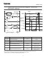
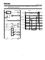
1.1.1. Switching circuit connection diagram, Time chart,
Parameter settings
Title Function Adjustment range Setting value
Output signal selection of commercial
power/inverter switching
0 to 3
1 (Automatic switching in case
of trip)
*3
Inverter side switching waiting time 0.1 to 10.0 seconds Different for each model
*3
Commercial power side switching waiting
time
0.37 to 10.0 seconds 0.62
*1
Input terminal selection #6 (S2) 0 to 135
20
(Emergency stop)
Output terminal selection #1 (OUT1) 0 to 119
46
(Commercial power/inverter
switching output 1)
Output terminal selection #2 (OUT2) 0 to 119
48
(Commercial power/inverter
switching output 2)
*1:Be careful about Items 5 and 7 in 1.3, “Precautions.”
*2:Due to internal processing timing, inverter-side wait time become 0.5 second longer than the setting value of
*3: and are included the operation time of the relay and the magnet contactor.
In almost all cases, it is not necessary to change these parameter settings.
Setting
frequency
Inverter-side switching wait
time
*2
Frequency after speed is
detected
Commercial power
switching wait time
S
p
eed detection time
Inverter run
Commercial power run
P24-OUT1(RY1)
for inverter
run
output
P24-OUT2(RY2)
for commercial
power run
output
Run signal
F-CC
Stand-by signal
ST-CC
ON
ON
ON
ON
ON
0Hz
Reset signal
RES-CC
Inverte
r
trip occurs
ON
Inverter run
Inverter protective
action signal
F L
FLA FLC
FLX
X
F
OFFON
X
MC3
MC2
RY1
(
Inverter
)
X
MC3
MC1
MC2
RY2
(Commercial
p
ower
)
X

E6581364
4
1.2. Standard connection diagram (Star-delta switching start)
This is the circuit to switch the motor to commercial power supply Star Delta (star-delta) connection
startup when the inverter’s protective function is activated.
FL
G / E
F
RES
CC
R/L1
S/L2
T/L3
U/T1
V/T2
W/T3
FLC
FLB
FLA
S1
ST
R
S2
S3
OUT2
P24/PLC
OUT1
RY2
PO
PB
PC/-
PA/+
Main circuit
MCCB
I M
RY1
MC3
*2
MC2
*3
MC1
*2
MCY
MCD
For motor protection
THR
*4
Motor
Run
command
Stand-by
*7
Reset
*6
Emergency
stop
*5
Protective action
detection
relay
Common
+SU
Control
circuit
CCA
RX
VI/II
RR/S4
PP
A
M
FM
OUT1
NO
CC
*1: The control power supply backup option (Model: CPS002Z) is needed.
*2: Observe the Item 1 in 1.3, “Precautions.”
*3: See Item 2 in 1.3, “Precautions.”
*4: Be careful about Items 3 in 1.3, “Precautions.”
*5:
Be careful about Items 5 and 7 in 1.3, “Precautions.”
*6: Be careful about Item 6 in 1.3, “Precautions.
Control power supply
backup option
*1
*7: VF-AS1's 'WP1/WN1' model and VF-PS1 don't have 'ST'
terminal. Please set next parameter for use 'S3' terminal as
'ST' function.
f110 (Always ON function selection 1) = 0
f117 (Input terminal function selection: S3) = 6

E6581364
5
1.2.1. Switching circuit connection diagram, Time chart,
Parameter settings
ON
Setting
frequency
S
p
eed detection time
Inverte
r
trip occurs
Frequency after speed is
detected
P24-OUT1(RY1)
for inverter
run
output
P24-OUT2(RY2)
for commercial
power run
output
Run signal
F-CC
Stand-by signal
ST-CC
Reset signal
RES-CC
Inverter-side switching
wait time
*2
Commercial power
switching wait time
Inverter run
Commercial power run
Inverter run
ON
ON
ON
ON
ON
0Hz
Y- Switching timer
F L
FLA FLC
FLX
X
MC3
MC1
F
OFFON
X
MC2
RY2
(Commercial
power)
MC3
X
X
MC
Y
MCD
MCD
MC
Y
MC1
Inverter protective
action signal
MC2
RY1
(
Inverter
)

E6581364
6
Title
Function Adjustment range Setting value
Output signal selection of commercial
power/inverter switching
0 to 3
1 (Automatic switching when
tripped)
*3
Inverter side switching waiting time 0.1 to 10.0 seconds Different for each model
*3
Commercial power side switching waiting
time
0.37 to 10.0 seconds 0.62
*1
Input terminal selection #6 (S2) 0 to 135
20
(Emergency stop)
Output terminal selection #1 (OUT1) 0 to 119
46
(Commercial power/inverter
switching output 1)
Output terminal selection #2 (OUT2) 0 to 119
48
(Commercial power/inverter
switching output 2)
*1:Be careful about Items 5 and 7 in 1.3, “Precautions.”
*2:Due to internal processing timing, inverter-side wait time become 0.5 second longer than the setting value of
*3: and are included the operation time of the relay and the magnet contactor.
In almost all cases, it is not necessary to change these parameter settings.
1.3. Precautions
1. Make sure to interlock the magnetic contactor (MC3) on the inverter output side with the
commercial power supply magnetic contactor (MC1).
2. Magnetic contactor (MC2) can be omitted for normal operation but this is needed to isolate the
inverter circuit in case a short-circuit fault occurs inside the inverter. Examine whether it should
be installed or not considering the importance of the system concerned.
3. Check to make sure the phase sequence of the inverter and that of the commercial power
supply are the same beforehand to maintain the motor’s rotational direction unchanged before
and after the power switching.
4. In the
(Reverse-run prohibition), do not use the forward direction disable setting
(
=2). Switching to commercial power supply cannot be made because the inverter
cannot run forward.
5. If the cause of the inverter trip was OCL (short-circuit on the load side at startup), E (emergency
stop) or EF1, 2 (ground fault), commercial power supply /inverter switching output 1, 2 (output
terminal selection 46, 48) are both shut off and MC1 and MC3 on both inverter and commercial
power supply sides disabled and unable to turn on.
6. In case an inverter trip occurs, remove the cause of the protective action and then reset the
inverter to start the inverter again.
7. S2 terminal (emergency stop) can be omitted, but it is needed as a circuit to detect a motor
overload when the motor is operated on commercial power supply. Examine whether it should
be installed or not considering the importance of the system concerned.
8. Regarding the selection of MCCB used when the backup circuit starts in star delta configuration,
you have to consider the peak current when star connection is switched to delta connection.
9. In the case the motor’s connection is star-delta, use delta connection when the inverter is
running. (Do not switch star delta connection while the inverter is running.)

E6581364
7
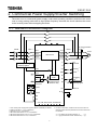
2. Commercial Power Supply/Inverter Switching
The motor runs on commercial power supply under rated operating conditions and when the motor
runs in energy saving mode with its input power frequency lowered, this circuit switches the motor
to the inverter power without stopping the motor.
2.1. Standard connection diagram
*1: The control power supply backup option (Model: CPS002Z) is needed.
*2: Observe the Item 1 in 2.2, “Precautions.”
*3: See Item 2 in 2.2, “Precautions.”
*4: Be careful about Items 3 in 2.2, “Precautions.”
*5:
Be careful about Items 5 and 7 in 2.2, “Precautions.”
*6: Be careful about Item 6 in 2.2, “Precautions.
MC1
*2
For motor protection
THR
*4
Motor
FL
G / E
F
RES
CC
R/L1
S/L2
T/L3
U/T1
V/T2
W/T3
FLC
FLB
FLA
Run
command
S1
ST
R
S2
S3
OUT2
P24/PLC
OUT1
RY2
PO
PB
PC/-
PA/+
Main circuit
Stand-by
*7
Reset
*6
Emergency
stop
*5
CCA
RX
VI/II
RR/S4
PP
A
M
FM
OUT1
MCCB
Common
I M
RY1
Protective action
detection
relay
MC3
*2
MC2
*3
+SU
Control
circuit
Control power supply
backup option
*1
NO
CC
Commercial run
switching signal
*7: VF-AS1's 'WP1/WN1' model and VF-PS1 don't have 'ST'
terminal. Please set next parameter for use 'S3' terminal as
'ST' function.
f110 (Always ON function selection 1) = 0
f115 (Input terminal function selection: S1) = 6

E6581364
8
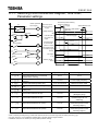
2.1.1. Switching circuit connection diagram, Time chart,
Parameter settings
Title Function Adjustment range Setting value
Output signal selection of commercial
power/inverter switching
0 to 3 2 or 3
Commercial power/inverter switching
frequency
0 to Power supply frequency
*3
Inverter side switching waiting time 0.1 to 10.0 seconds Different for each model
*3
Commercial power side switching waiting
time
0.37 to 10.0 seconds 0.62
Commercial power switching frequency
holding time
0.1 to 10.0 seconds 2.0
*1
Input terminal selection #6 (S2) 0 to 135
20
(Emergency stop)
Input terminal selection #7 (S3) 0 to 135
102
(Commercial power run
switching)
Output terminal selection #1 (OUT1) 0 to 119
46
(Commercial power/inverter
switching output 1)
Output terminal selection #2 (OUT2) 0 to 119
48
(Commercial power/inverter
switching output 2)
*1:Be careful about Items 5 and 7 in 2.2, “Precautions.”
*2:Due to internal processing timing, inverter-side wait time become 0.5 second longer than the setting value of
*3: and are included the operation time of the relay and the magnet contactor.
In almost all cases, it is not necessary to change these parameter settings.
Commercial power
switching frequency
Commercial power switching
frequency hold time
Commercial power
run switching signal
S3-CC
ON
ON
ON
ON
ON
ON
0Hz
ON
Inverter-side switching
wait time
*2
Frequency after speed is
detected
Commercial power
switching wait time
S
p
eed detection time
Inverter run
Commercial power run Inverter run
Setting frequency
P24-OUT1(RY1)
for inverter
run
output
P24-OUT2(RY2)
for commercial
power run
output
Run signal
F-CC
Stand-by signal
ST-CC
F L
FLA FLC
FLX
S3
MC3
MC1
F
(
Inverter
)
(Commercial
power)
S3
RY1(Inverter)
RY2(Commercial
p
ower
)
MC3
Inverter protective
action signal
MC2
MC2

E6581364
9
2.2. Precautions
1. Make sure to interlock the magnetic contactor (MC3) on the inverter output side with the
commercial power supply magnetic contactor (MC1).
2. Magnetic contactor (MC2) can be omitted for normal operation but this is needed to isolate the
inverter circuit in case a short-circuit fault occurs inside the inverter. Examine whether it should
be installed or not considering the importance of the system concerned.
3. Check to make sure the phase sequence of the inverter and that of the commercial power
supply are the same beforehand to maintain the motor’s rotational direction unchanged before
and after the power switching.
4. In the
(Reverse-run prohibition), do not use the forward direction disable setting
(
=2). Switching to commercial power supply cannot be made because the inverter
cannot run forward.
5. If the cause of the inverter trip was OCL (short-circuit on the load side at startup), E (emergency
stop) or EF1, 2 (ground fault), commercial power supply / inverter switching output 1, 2 (output
terminal selection 46, 48) are both shut off and MC1 and MC3 on both inverter and commercial
power supply sides disabled and unable to turn on.
6. When the setting value for (output signal selection of commercial power supply/inverter
switching) is “2”, the system does not work even if the commercial power supply switching
signal is turned on at the time of an inverter trip.
To switch to commercial power supply, remove the cause of the protective action and reset the
inverter and then enter the switching signal to switch to commercial power supply.
7. S2 terminal (emergency stop) can be omitted, but it is needed as a circuit to detect a motor
overload when the motor is operated on commercial power supply. Examine whether it should
be installed or not considering the importance of the system concerned.
-
 1
1
-
 2
2
-
 3
3
-
 4
4
-
 5
5
-
 6
6
-
 7
7
-
 8
8
-
 9
9
-
 10
10


Ask a question and I''ll find the answer in the document
Finding information in a document is now easier with AI
Related papers
-
Toshiba Welding System VF-A7 User manual
-
-
-
-
-
Toshiba VF-AS1 TOSVERT VF-AS1 User manual
-
-
-
Other documents
-
 Sun Mountain Micro Cart User manual
-
 Tacens MC3 Datasheet
-
 Sun Mountain Micro Cart User manual
-
CARLO GAVAZZI VariFlex3 RVFFC3402200F User manual
-
ESAB 200 ULTRA-CUT™ Plasma Cutting System User manual
-
Mitsubishi Electric FR-A7AR/FR-A7AR E kit User manual
-
-
Mitsubishi Electric FR-A540-45K-EC User manual
-
-


