Kramer MTX3-16-M User guide

Category
Gateways/controllers
Type
User guide

Kramer MTX3-16-M is a flexible I/O digital matrix switcher that offers extensive connectivity options and powerful features for routing and managing audio and video signals. With its modular design, it allows for customization by adding up to 8 card modules, providing a wide range of input and output options. The MTX3-16-M excels in switching, processing, and routing audio and video signals, making it ideal for various applications such as conference rooms, auditoriums, and live events.

Kramer MTX3-16-M is a flexible I/O digital matrix switcher that offers extensive connectivity options and powerful features for routing and managing audio and video signals. With its modular design, it allows for customization by adding up to 8 card modules, providing a wide range of input and output options. The MTX3-16-M excels in switching, processing, and routing audio and video signals, making it ideal for various applications such as conference rooms, auditoriums, and live events.

MTX3-16-M Quick Start
P/N:
2900- 301597QS
Rev:
2
Scan for full manual
Step 1: Check what’s in the box
MTX3-16-M Flexible I/O Digital Matrix Switcher
1 Set of rack ears (attached)
1 Quick start guide
2 Power cords
Step 2: Get to know your MTX3-16-M
#
Feature
Function
1
Numeric
Keypad
Numbers
1 to 0
(Backward)
Move the LCD display left (when there is an extended display).
(Forward)
Move the LCD display right (when there is an extended display).
2
Double-Function
Selector Buttons
Area.
Enabled and lit
after pressing
the MENU
button 4 times.
Menu Button
Function
ALL
Connect an input to all outputs.
3
STO
Store the current setup in a preset.
4
EDID
Assign EDID channels.
5
ESC
Exit the current operation.
6
OFF
Turn off an output.
7
RCL
Recall a preset.
8
DELAY
Set the delay between confirming an action and the execution of the
action on an output port.
9
ENTER
Confirm the input-output setup when using a one-digit number instead
of two digits. For example, to enter input 5, you can press either 05 or
5, ENTER.
Press to enter the options in a setup menu.
10
TAKE Button
Confirm action.
11
MENU Button
Enable the ALL, STO, EDID, ESC, OFF, RCL, DELAY and ENTER buttons.
Press again to enter the configuration menu.
When in a menu, press to cycle through the menu items.
#
Feature
Function
12
EXIT MENU Button
Press to exit a menu or return to switching mode.
13
LOCK Button
Press and hold for approximately 2 sec to lock/unlock the front panel buttons.
A short press returns the LCD display to the default window.
14
DEFAULT SETUP Button
Press to open the reset menu on the display.
15
SERVICE Mini USB Connector
Connect to a PC to send Protocol 3000 commands.
16
OUTPUTS/INPUTS
LCD Display
Displays the outputs (upper row) routed to the selected inputs (lower row).
Displays user interface messages and menus.
17
POWER LED (PS-1 / PS-2)
Lights green when the power supply is active.
18
ERROR LED (PS-1 / PS-2)
Lights red when an error is detected. Briefly lights red immediately following a power
disruption (e.g., cable disconnection, power off, and so on).
#
Feature
Function
19
Slots for up to 4 card modules
The left side of MTX3-16-M has 4 slots for insertion of card modules and the right
side (26) has another 4 slots. In total 8 card modules can be inserted.
MTX3-16-M uses hot plugging, so cards can be inserted while the device is
operating, and the card’s ports will automatically be categorized as input or output.
Use the system menus to change input/output designations and to create flexible
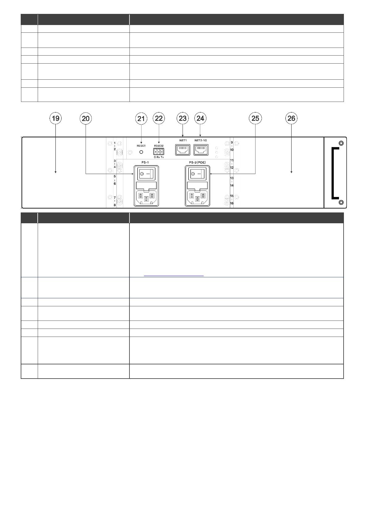
connections between the ports on different cards.
MTX3-16-M identifies ports by the ID numbers it allocates to each card slot:
See MTX3-16-M ID numbers below to understand how they are defined.
20
PS-1 Power Module and Switch
Supplies power to the device and has a fuse holder. The device only operates when
PS-1 is switched on. Connect to the mains supply and switch on to power the device.
The PS1 power LED (17) lights green.
21
RESET Recessed Button
Press to reboot the MTX3-16-M control card.
22
RS-232 3-pin Terminal Block
Connector
Connect to a remote operation PC or a remote controller.
23
NET 1 RJ-45 Connector
Connect to a PC or controller via the Ethernet LAN (100Mb).
24
NET 2-1G RJ-45 Connector
Connect to a PC or controller via the Ethernet LAN (100/1000Mb).
25
PS-2 (POE) Power Module and
Switch
Supplies 48V for inserted cards delivering PoE (power over ethernet) and has a fuse
holder. PoE will be supplied if PS-2 is on and PS-1 is off, but MTX3-16-M itself won’t
operate. Connect PS-2 to the mains supply and switch on if required, the PS2 power
LED (18) lights green.
26
Slots for up to 4 card modules
See (19) for the explanation. The 4 card insertion slots on the right side of the device
use IDs 9 to 16.
MTX3-16-M ID numbers
When a card module is inserted into MTX3-16-M, it is allocated 2 ID numbers which are used to identify the card’s input/output
ports. In total there are 16 ID numbers available, 2 for each inserted card. The ID numbers available for each slot are written
on the chassis, next to the insertion points.
Ports on the left side of an inserted card module receive one ID number and ports on the right side of the card module receive
the next consecutive ID number. Input/output directions are defined per ID number.
Card modules can have up to 4 input/output ports. If one side of a card module has more than 2 ports, those ports have the
same ID and input/output direction.
Step 3: Install the MTX3-16-M
To rack mount the machine, attach both rack ears (by
removing the screws from each side of the machine
and replacing those screws through the rack ears) or
place the machine on a table.
Ensure that the environment (e.g., maximum ambient
temperature & air flow) is compatible for the device.
Avoid uneven mechanical loading.
Make appropriate consideration of equipment nameplate
ratings to avoid overloading the circuits.
Maintain reliable earthing of rack-mounted equipment.
Step 4: Connect the inputs and outputs
Insert the input and output cards into the card slots and then connect the inputs and the outputs.
You can insert cards into slots while the device is powered.
For optimum range and performance use the recommended Kramer cables
available at www.kramerav.com/product/MTX3-16-M.
Using third-party cables may cause damage!
Step 5: Connect the power
Connect the power cord to MTX3-16-M and plug it into the mains electricity.
Safety Instructions (See www.kramerav.com for updated safety information)
Caution:
For products with relay terminals and GPI\O ports, please refer to the permitted rating for an external connection, located next to the terminal or
in the User Manual.
There are no operator serviceable parts inside the unit.
Warning:
Use only the power cord that is supplied with the unit.
Disconnect the power and unplug the unit from the wall before installing.
Do not open the unit. High voltages can cause electrical shock! Servicing by qualified personnel only.
To ensure continuous risk protection, replace fuses only according to the rating specified on the product label which located on the bottom of the
unit.
Step 6: Set operation parameters
To operate MTX3-16-M from the front panel, use the
numeric keypad.
When the unit is powered-on, the last matrix setup
that was used is loaded.
To retrieve another setup, use recall setup (4
presses of the Menu button) to load a stored
configuration from a preset or press Default Setup to
reset the matrix to the default setup or factory default
setup.
VOSW lists video output port IDs and VISW shows
the video input port ID connected to the ID above it.
While powering up, the LCD display shows the following screens
in sequence:
Step 7: Operate the MTX3-16-M
Operate MTX3-16-M via:
Front panel buttons.
Embedded web pages over the Ethernet.
The first time you enter, you will be asked to
set a new password.
Remotely, using RS-232 serial commands
transmitted from a touch screen system, PC
or a serial controller.
Protocol 3000 commands transmitted over
the Ethernet.
Protocol 3000 commands transmitted
through the mini-USB Service port.
RS-232 Control / Protocol 3000
Baud Rate:
115,200
Parity:
None
Data Bits:
8
Command Format:
ASCII
Stop Bits:
1
Example: (Switch video input 2 to output 4): #Vid 2>4<CR>
Default Ethernet Parameters
IP Address:
192.168.1.39
UDP Port #:
50000
Subnet mask:
255.255.0.0
TCP Port #:
5000
Gateway:
192.168.0.1
Default User:
Default Password:
admin
M01@kramer
Using the embedded web pages
Click the navigation pane to open the following pages:
Routing Settings Change the video or audio
input/output routing.
Account Management Create new users with two
levels of authorization.
EDID Management Copy EDIDs from outputs to
inputs.
Settings Change device, card and port
configuration, including IP, firmware and factory reset.
Status Monitor operation status of cards, power
supplies, PoE and fans.
About View current webpage version and
manufacturer information
The terms HDMI, HDMI High-Definition Multimedia Interface, and the HDMI Logo are trademarks or registered trademarks of HDMI Licensing Administrator, Inc.
  • Page 1 1
  • Page 2 2
  • Page 3 3
  • Page 4 4

Kramer MTX3-16-M User guide

Category
Gateways/controllers
Type
User guide

Kramer MTX3-16-M is a flexible I/O digital matrix switcher that offers extensive connectivity options and powerful features for routing and managing audio and video signals. With its modular design, it allows for customization by adding up to 8 card modules, providing a wide range of input and output options. The MTX3-16-M excels in switching, processing, and routing audio and video signals, making it ideal for various applications such as conference rooms, auditoriums, and live events.

Ask a question and I''ll find the answer in the document

Finding information in a document is now easier with AI