Page is loading ...


Kramer Electronics Ltd.
MV-4X – Contents
i
Contents
Introduction 1
Getting Started 1
Overview 2
Typical Applications 3
Controlling your MV-4X 4
Defining MV-4X 4 Window Multi-viewer/4x2 Seamless Matrix Switcher 5
Mounting MV-4X 7
Connecting MV-4X 8
Connecting the Output to a Balanced/Unbalanced Stereo Audio Acceptor 9
Connecting to MV-4X via RS-232 9
Wiring RJ-45 Connectors 9
Operating and Controlling MV-4X 10
Using Front Panel Buttons 10
Controlling and Operating Via the OSD Menu 10
Operating via Ethernet 21
Using Embedded Web Pages 25
General Operation Settings 27
Defining the Matrix Mode Parameters 31
Defining the Multi-View Parameters 34
Defining the Auto-Layout Parameters 40
Managing EDID 41
Defining General Settings 44
Defining Interface Settings 46
Defining MV-4X User Access 47
Defining Advanced Settings 48
Defining OSD Settings 51
Configuring a Logo 52
Viewing the About Page 54
Technical Specifications 55
Default Communication Parameters 56
Default EDID 56
Protocol 3000 59
Understanding Protocol 3000 59
Protocol 3000 Commands 60
Result and Error Codes 71

Kramer Electronics Ltd.
MV-4X – Introduction
1
Introduction
Welcome to Kramer Electronics! Since 1981, Kramer Electronics has been providing a world
of unique, creative, and affordable solutions to the vast range of problems that confront the
video, audio, presentation, and broadcasting professional on a daily basis. In recent years, we
have redesigned and upgraded most of our line, making the best even better!
Getting Started
We recommend that you:
• Unpack the equipment carefully and save the original box and packaging materials for
possible future shipment.
• Review the contents of this user manual.
Go to www.kramerav.com/downloads/MV-4X to check for up-to-date user manuals,
application programs, and to check if firmware upgrades are available (where appropriate).
Achieving Best Performance
• Use only good quality connection cables (we recommend Kramer high-performance,
high-resolution cables) to avoid interference, deterioration in signal quality due to poor
matching, and elevated noise levels (often associated with low quality cables).
• Do not secure the cables in tight bundles or roll the slack into tight coils.
• Avoid interference from neighboring electrical appliances that may adversely influence
signal quality.
• Position your Kramer MV-4X away from moisture, excessive sunlight and dust.
Safety Instructions
Caution:
• This equipment is to be used only inside a building. It may only be connected to other
equipment that is installed inside a building.
• For products with relay terminals and GPI\O ports, please refer to the permitted rating
for an external connection, located next to the terminal or in the User Manual.
• There are no operator serviceable parts inside the unit.
Warning:
• Use only the power cord that is supplied with the unit.
• To ensure continuous risk protection, replace fuses only according to the rating
specified on the product label which is located on the bottom of the unit.

Kramer Electronics Ltd.
MV-4X – Introduction
2
Recycling Kramer Products
The Waste Electrical and Electronic Equipment (WEEE) Directive 2002/96/EC aims to reduce
the amount of WEEE sent for disposal to landfill or incineration by requiring it to be collected
and recycled. To comply with the WEEE Directive, Kramer Electronics has made
arrangements with the European Advanced Recycling Network (EARN) and will cover any
costs of treatment, recycling and recovery of waste Kramer Electronics branded equipment on
arrival at the EARN facility. For details of Kramer’s recycling arrangements in your particular
country go to our recycling pages at www.kramerav.com/il/quality/environment.
Overview
Congratulations on purchasing your Kramer MV-4X 4 Window Multi-viewer/4x2 Seamless
Matrix Switcher.
MV-4X is a high-performance HDMI matrix switcher with integrated scaling technology and
multi-windowing options. It is an ideal solution for monitoring or displaying multiple sources
simultaneously for use in control rooms, conference rooms or classrooms. Video resolutions
up to 4K@60Hz 4:4:4 and LPCM audio up to 7.1 channels and 192kHz are supported on both
input and output. In addition, MV-4X is fully compatible with the HDCP 1.x and 2.3 standards.
The product offers 2 outputs – HDMI and HDBT. Users can choose to display any of the four
HDMI sources individually, in full screen, or in a variety of multi-window modes that include
quad mode, PiP, and PoP on both outputs. Alternatively, MV-4X MV-4Xoffers a seamless
(zero-time video cut) 4x2 matrix switcher option. The product also supports chroma-keying
and includes a logo overlay feature.
You can control and manage the MV-4X, including the input/window routing, position, and
size via the front panel OSD buttons, Ethernet (with embedded webpages), and RS-232.
MV-4X provides exceptional quality, advanced and user-friendly operation, and flexible
control.
Exceptional Quality
• High Performance Multi-Viewer – 18G 4K HDMI product with 4 HDMI inputs and HDBT
and HDMI outputs that supports HDMI up to 4K@50/60Hz 4:4:4 and HDBT up to
4K@50/60Hz 4:2:0.
• Zero-Time Video Cuts – Connect up to four HDMI sources, an HDMI and an HDBT sink,
and seamlessly switch between them.
• HDMI Support – HDR10, CEC (for outputs only), 4K@60Hz, Y420, BT.2020, Deep Color
(for inputs only), x.v.Color™, 7.1 PCM, Dolby TrueHD, DTS-HD, as specified in HDMI
2.0.
• Content Protection – Supports HDCP 2.3.
• Chroma Keying Support – Select to key the video input using a uniform-colored
background.
• Includes numerous filters and algorithms that eliminate picture artifacts.

Kramer Electronics Ltd.
MV-4X – Introduction
3
Advanced and User-friendly Operation
• Matrix Switching – Truly seamless zero-time 4x2 switching in Matrix mode.
• Multiple Display Options – Display any of 4 HDMI sources individually, full screen, with
seamless switching in Matrix mode. Or choose to display the sources using multi-
window modes such as fully customizable standard views like PiP (Picture in Picture)
and PoP (Picture outside of Picture) as well as Quad-window modes.
• 4 Preset Memory Locations – Supports storage of multi-window arrangements as a
preset for later use.
• Auto Layout Support – Auto-window mode that automatically changes the number of
visible windows based on the number of live sources.
• Independent audio source selection in all modes.
• Image Rotation – 90, 180 and 270-degree rotation support for 4K output resolutions on
input 1 in matrix mode.
• Selectable Border Design – Each window can have a border with a selectable color.
• Logo Support – Upload and freely position a graphic logo overlay as well as a boot
screen logo.
• Multi-view window Setup – Intuitive and easy adjustment of window size, position, and
settings.
• User-friendly Control – Via the built-in Web GUI, as well via the OSD-driven front-panel
switches.
• EDID Management – Per-input EDID management with internal or external EDID options.
• Local Monitor View – Matrix mode is ideal for applications where the user requires a
local monitor to view the image on the display before switching it to the remote display.
Flexible Connectivity
• 4 HDMI inputs.
• 1 HDMI output and 1 HDBT output.
• De-embedded analog balanced stereo audio output.
Typical Applications
MV-4X is ideal for these typical applications:
• Meeting rooms - Allows users to show multiple presentations simultaneously.
• Distance learning classrooms – Enables to show the main picture content, while the
teacher shows in the Picture-in-picture (PiP) window.
• Medical – Quad view for operating theatres.
• Shopping malls and residential – Shows multiple images at the same time.
• Video editing, post production and applications that require chroma keying.

Kramer Electronics Ltd.
MV-4X – Introduction
4
Controlling your MV-4X
Control your MV-4X directly via the front panel push buttons, with on-screen menus, or:
• By RS-232 serial commands transmitted by a touch screen system, PC, or other serial
controller.
• Remotely through the Ethernet using built-in user-friendly Web pages.
• Direct connections for HDBT tunneling of IR and RS-232.
• Optional - USB port to upgrade the firmware, upload the EDID, and Logo.

Kramer Electronics Ltd.
MV-4X – Defining MV-4X 4 Window Multi-viewer/4x2 Seamless Matrix Switcher
5
Defining MV-4X 4 Window
Multi-viewer/4x2 Seamless Matrix
Switcher
This section defines MV-4X.
Figure 1: MV-4X 4 Window Multi-viewer/4x2 Seamless Matrix Switcher Front Panel
#
Feature
Function
1
INPUT Selector Buttons (1 to 4)
Press to select an HDMI input (from 1 to 4) to switch to an output.
2
OUTPUT (in
Matrix Mode)
Selector Button
Press to select an output.
LEDs (A and B)
Light green when output A (HDMI) or B (HDBT) are selected.
3
WINDOW (in
Multiview Mode)
Selector Button
Press followed by an input button to connect the selected input to a
window.
For example, select Window 3 and then Input button # 2 to connect
input # 2 to Window 3.
LEDs (1 to 4)
Light green when a window is selected.
4
MATRIX Button
Press to operate the system as a 4x2 matrix switcher.
5
QUAD Button
Press to display all four inputs on each of the outputs. Layouts are
configured via the embedded web pages.
6
PIP Button
Press to display one input in the background and the other images as
PiP (Picture-in-Picture) over that image. Layouts are configured via the
embedded web pages.
7
MENU Button
Press to access the OSD menu, exit the OSD menu and, when in the
OSD menu, move to the previous level in the OSD screen
8
Navigation
Buttons
Press to decrease numerical values or select from several definitions.
Press to move up the menu list values.
Press to increase numerical values or select from several definitions.
Press to move down the menu list.
Enter
Press to accept changes and change the SETUP parameters.
9
RESET TO XGA/1080P Button
Press and hold for about 2 seconds to toggle the output resolution
between XGA and 1080p, alternatively.
10
PANEL LOCK Button
To lock, press and hold PANEL LOCK button for about 3 seconds.
To unlock, press and hold PANEL LOCK and RESET TO buttons for
about 3 seconds.

Kramer Electronics Ltd.
MV-4X – Defining MV-4X 4 Window Multi-viewer/4x2 Seamless Matrix Switcher
6
Figure 2: MV-4X 4 Window Multi-viewer/4x2 Seamless Matrix Switcher Front Panel
#
Feature
Function
11
HDMI IN Connectors (1 to 4)
Connect to up to 4 HDMI sources.
12
AUDIO OUT 5-pin Terminal Block
Connector
Connect to a balanced stereo audio acceptor.
13
HDBT
IR IN RCA Connector
Connect to an IR sensor to control a device connected to the HDBT
receiver via IR Tunneling.
IR OUT RCA Connector
Connect to an IR emitter to control a device that is connected to MV-4X
from the HDBT receiver side via HDBT tunneling.
14
HDBT RS-232 3-pin Terminal Block
Connector
Connect to a device for RS-232 HDBT tunneling.
15
RS-232 3-pin Terminal Block
Connector
Connect to a PC to control the MV-4X.
16
HDMI OUT A Connector
Connect to an HDMI acceptor.
17
HDBT OUT B RJ-45 Connector
Connect to a receiver (for example, TP-580Rxr).
18
PROG USB Connector
Connect to a USB stick to perform firmware upgrades and/or upload a
Logo.
19
ETHERNET RJ-45 Connector
Connect to a PC via a LAN
20
12V/2A DC Connector
Connect to the supplied power adapter.
The terms HDMI, HDMI High-Definition Multimedia Interface, and the HDMI Logo are trademarks or registered trademarks of HDMI Licensing Administrator, Inc.

Kramer Electronics Ltd.
MV-4X – Mounting MV-4X
7
Mounting MV-4X
This section provides instructions for mounting MV-4X. Before installing, verify that the
environment is within the recommended range:
• Operation temperature – 0 to 40C (32 to 104F).
• Storage temperature – -40 to +70C (-40 to +158F).
• Humidity – 10% to 90%, RHL non-condensing.
Caution:
• Mount MV-4X before connecting any cables or power.
Warning:
• Ensure that the environment (e.g., maximum ambient temperature & air flow) is
compatible for the device.
• Avoid uneven mechanical loading.
• Appropriate consideration of equipment nameplate ratings should be used for avoiding
overloading of the circuits.
• Reliable earthing of rack-mounted equipment should be maintained.
• Maximum mounting height for the device is 2 meters.
Mount MV-4X in a rack:
• Use the recommended rack adapter
(see www.kramerav.com/product/MV-4X).
Attach the rubber feet and place the unit on a flat surface.

Kramer Electronics Ltd.
MV-4X – Connecting MV-4X
8
Connecting MV-4X
Always switch off the power to each device before connecting it to your MV-4X. After
connecting your MV-4X, connect its power and then switch on the power to each device.
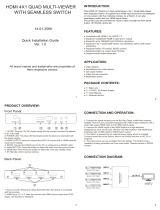
Figure 3: Connecting to the MV-4X Rear Panel
To connect MV-4X as illustrated in the example in Figure 3:
1. Connect up to 4 HDMI sources (for example, Blu-ray players, a work station and set top
box) to the HDMI IN connectors .
2. Connect the HDMI OUT A connector to an HDMI acceptor (for example, a display).
3. Connect the HDBT OUT B RJ-45 port to a Receiver (for example, Kramer
TP-580Rxr).
4. Connect the AUDIO OUT 5-pin Terminal block connector to balanced stereo audio
active speakers.
5. Set IR control from the connected receiver to the Blue-ray player that is connected to
HDMI IN 3 (by pointing the Blu-ray IR remote control to the IR receiver):
▪ Connect an IR receiver cable to the TP-580Rxr receiver.
▪ Connect an IR emitter cable from the IR OUT RCA connector to the IR receiver on
the Blue-ray player.
6. Connect the RS-232 3-pin terminal block connector to a laptop.
7. Connect the power adapter to MV-4X and to the mains electricity (not shown in
Figure 3).
11
16
17
12

Kramer Electronics Ltd.
MV-4X – Connecting MV-4X
9
Connecting the Output to a Balanced/Unbalanced
Stereo Audio Acceptor
The following are the pinouts for connecting the output to a balanced or unbalanced stereo
audio acceptor:
Figure 4: Connecting to a Balanced Stereo Audio
Acceptor
Figure 5: Connecting to an Unbalanced Stereo Audio
Acceptor
Connecting to MV-4X via RS-232
You can connect to MV-4X via an RS-232 connection using, for example, a PC.
MV-4X features an RS-232 3-pin terminal block connector allowing the RS-232 to control
MV-4X.
Connect an RS-232 terminal block on the rear panel of MV-4X to a PC/controller, as follows:
From the RS-232 9-pin D-sub serial port connect:
• Pin 2 to the TX pin on the MV-4X RS-232 terminal block
• Pin 3 to the RX pin on the MV-4X RS-232 terminal block
• Pin 5 to the G pin on the MV-4X RS-232 terminal block
RS-232 Device MV-4X
Wiring RJ-45 Connectors
This section defines the TP pinout, using a straight pin-to-pin cable with RJ-45 connectors.
For HDBT cables, it is recommended that the cable ground shielding be connected/soldered
to the connector shield.
EIA /TIA 568B
PIN
Wire Color
1
Orange / White
2
Orange
3
Green / White
4
Blue
5
Blue / White
6
Green
7
Brown / White
8
Brown
13

Kramer Electronics Ltd.
MV-4X – Operating and Controlling MV-4X
10
Operating and Controlling MV-4X
Using Front Panel Buttons
MV-4X front panel buttons enable the following actions:
• Selecting an HDMI INPUT .
• Selecting an output (A or B) .
• Directing an input to a selected window using the WINDOW button and the INPUT
buttons (from 1 to 4) .
• Selecting operation modes (MATRIX , QUAD or PIP modes).
• Controlling and operating MV-4X via the OSD menu buttons ( and ).
• Resetting the resolution (to XGA/1080p) .
• Locking the front panel .
Controlling and Operating Via the OSD Menu
MV-4X enables controlling and defining the device parameters via the OSD, using the front
panel MENU buttons.
To enter and use the OSD menu buttons:
1. Press MENU.
2. Press:
▪ ENTER to accept changes and to change the menu settings.
▪ Arrow buttons to move through the OSD menu, which is displayed on the video
output.
▪ EXIT to exit the menu.
The default OSD timeout is set to 10 seconds.
Use the OSD menu to perform the following operations:
• Setting the Video Mode on page 11.
• Selecting the Window Layout Mode on page 12.
• Configuring Chroma Key Mode on page 13.
• Setting up the Picture Parameters on page 14.
• Defining the Audio Output Settings on page 14.
• Setting the Input EDID on page 15.
• Configuring HDCP Mode on page 16.
1
2
3
1
4
5
6
7
8
9
10

Kramer Electronics Ltd.
MV-4X – Operating and Controlling MV-4X
11
• Setting OSD Parameters on page 17.
• Configuring the Logo Settings on page 18.
• Setting Ethernet Parameters on page 19.
• Setting the Preset Parameters on page 20.
• Configuring the Setup on page 20.
• Viewing the Information on page 21.
Setting the Video Mode
MV-4X enables setting the video operation mode.
To set the video mode:
1. On the front panel press MENU. The OSD menu appears.
2. Click Video Mode, select:
▪ Matrix, and perform the following actions:
Menu Item
Action
Options
Fade In/Out
Enable or disable crossfading between
sources in Matrix mode.
On, Off (default)
Fade Speed
Set the fade speed (in seconds).
1~10 (5 default)
OUT A/B Source
Select the source for output A (HDMI) and
output B (HDBT).
INPUT 1~4 (IN 1 default)
▪ PiP, PoP or Quad, and perform the following actions:
Menu Item
Action
Options
WIN 1/2/3/4
Source
Select the source for the specified
window. The selected configuration is
routed to output A and output B.
WIN 1 Source
In 1~4 (IN 1 default)
WIN 2 Source
In 1~4 (IN 2 default)
WIN 3 Source
In 1~4 (IN 3 default)
WIN 4 Source
In 1~4 (IN 4 default)
▪ Auto (see also Defining the Auto-Layout Parameters on page 40), and perform the
following actions:
Menu Item
Action
Options
WIN 1 to WIN 4
View the number of active windows.
2 options are displayed:
An active source is present, for
example, WIN 1>INPUT 2.
There is currently no active
source: Window Off.
Auto Layout
Full screen
Auto Layout 2
Select the preferred window
arrangement to use in Auto mode
when there are 2 active sources.
Side by Side (default), PoP or
PiP
Auto Layout 3
Select the preferred window
arrangement to use in Auto mode
when there are 3 active sources.
PoP Side or PoP Bottom
Auto Layout 4
Select the preferred window
arrangement to use in Auto mode
when there are 4 active sources.
Quad, PoP Side or PoP Bottom
▪ Preset 1, Preset 2, Preset 3, or Preset 4 (see Configuring/Recalling a Preset
on page 39).

Kramer Electronics Ltd.
MV-4X – Operating and Controlling MV-4X
12
Selecting the Window Layout Mode
MV-4X enables selecting the window layout for a specific video mode (see Setting the Video
Mode on page 11).
All settings are individually saved for each window and each mode.
To set the window layout mode:
1. On the front panel press MENU. The menu appears.
2. Click Window Layout.
3. Select an input:
▪ When in Matrix mode, select an input and perform the following actions:
Menu Item
Action
Options
Aspect Ratio
Select a fixed aspect ratio for the currently
selected window.
Full stretches the source to fill the output,
regardless of original aspect.
Best Fit automatically sets the ratio based
on the window’s current source resolution.
Full (default), 16:9, 16:10,
4:3, Best Fit
Mirror
Select Yes to flip the currently selected input
horizontally.
No (default), Yes
Rotate
Enable or disable rotating the input
counterclockwise by 90, 180 or 270 degrees.
Off (default), 90 degrees,
180 degrees, 270 degrees
When rotation is active, the output is
forced to full screen and the mirror
and border settings are disabled.
When the output resolution is set to
4K, only input 1 can be rotated.
Border On/Off
Enable or disable the color border around the
currently selected input.
On, Off (default)
Border Color
Select the color to use for the border of the
currently selected input.
Black, Red, Green (Win1
default), Blue (Win 2
default), Yellow (Win 3
default), Magenta (Win 4
default), Cyan, White, Dark
Red, Dark Green, Dark
Blue, Dark Yellow, Dark
Magenta, Dark Magenta,
Dark Cyan or Gray
Window Reset
Reset the current input to its default settings.
No (default), Yes
▪ When in PiP/PoP/Quad mode, select a window and perform the following actions:
Menu Item
Action
Options
Window On/Off
Enable or disable the currently selected
window.
On (default), Off
Position X
Set the X coordinate position of the upper left
corner of the currently selected window.
0~Max H Resolution
Position Y
Set the coordinate position of the upper left
corner of the currently selected window.
0~Max V Resolution
Size Width
Set the width of the currently selected
window.
1~Max H Resolution

Kramer Electronics Ltd.
MV-4X – Operating and Controlling MV-4X
13
Menu Item
Action
Options
Size Height
Set the height of the currently selected
window.
1~Max V Resolution
Priority
Select the layer priority of the currently
selected window. Priority 1 is at the front and
priority 4 is at the back.
Win 1 (layer 4, default),
Win 2 (layer 3, default),
Win 3 (layer 2, default),
Win 4 (layer 1, default)
Aspect Ratio
Select a fixed aspect ratio for the currently
selected window. The aspect ratio is based
on the window’s current height.
Full returns the window to the current
mode’s default size and shape for that
window.
Best Fit automatically sets the ratio based
on the window’s current source resolution.
Full (default), 16:9, 16:10,
4:3, Best Fit, User
Mirror
(Horizontal)
Select Yes to flip the currently selected input
horizontally.
No (default), Yes
Border On/Off
Enable or disable the color border around
the currently selected window.
On, Off (default)
Border Color
Select the color to use for the border of the
currently selected window.
Black, Red, Green (Win1
Default), Blue (Win 2
Default), Yellow (Win 3
Default), Magenta (Win 4
Default), Cyan, White, Dark
Red, Dark Green, Dark
Blue, Dark Yellow, Dark
Magenta, Dark Magenta,
Dark Cyan or Gray
Window Reset
Reset the current window to its default
settings.
No (default), Yes
Configuring Chroma Key Mode
MV-4X enables you to control the chroma key functions of the unit. Several pre-designed
standard key ranges are provided as well as slots to save up to 4 user-created key ranges.
Keying values and ranges are set using the full RGB color space (0~255).
Chroma Key is supported in Matrix Mode only.
To start the Chroma Key mode:
1. On the front panel press MENU. The menu appears.
2. Click Chroma Key and perform the following actions:
Menu Item
Action
Options
Chromakey
Select On to activate chroma keying.
When Chroma Key is active the aspect
ratio is forced to full screen and the
border feature is disabled.
On, Off (default)
User Select
Select the keying preset to use when
chroma key is active.
User 1 (default), User 2, User 3,
User 4, White, Yellow, Cyan,
Green, Magenta, Red, Blue,
Black
Red/Green/Blue
Max/Min:
Set the keying range (the color range
within the IN 2 video to make it
Red Max
0~255 (255 default)
Red Min
0~255 (0 default)

Kramer Electronics Ltd.
MV-4X – Operating and Controlling MV-4X
14
Menu Item
Action
Options
transparent) to use for the currently
selected User Key Preset by setting the
maximum and minimum values for red,
green, and blue.
If a fixed preset is currently selected,
the values are displayed, but cannot be
modified.
Green Max
0~255 (255 default)
Green Min
0~255 (0 default)
Blue Max
0~255 (255 default)
Blue Min
0~255 (0 default)
Chroma key is now configured.
Setting up the Picture Parameters
MV-4X enables setting the image parameters.
To set the picture parameters:
1. On the front panel press MENU. The menu appears.
2. Click Picture.
3. Select an input and perform the following actions:
Menu Item
Action
Options
Contrast
Set the contrast.
0, 1, 2, …100 (default 75)
Brightness
Set the brightness.
0, 1, 2, …100 (default 50)
Saturation
Set the saturation.
0, 1, 2, …100 (default 50)
Hue
Set the hue.
0, 1, 2, …100 (default 50)
Sharpness H/V
Set the H/V sharpness.
H Sharpness
0, 1, 2, …20 (default 10)
V Sharpness
0, 1, 2, …20 (default 10)
Reset
Set the sharpness.
No (default), Yes
Picture parameters are set.
Defining the Audio Output Settings
MV-4X enables defining the device audio output settings.
To define the Audio output settings:
1. On the front panel press MENU. The menu appears.
2. Click Audio and define the video parameters according to the information in the
following table:
▪ Audio: Matrix Mode
Menu Item
Action
Options
OUT A Source
Select the audio source to pair with video
output A.
IN 1 (default), IN 2, IN 3, IN 4,
Window
OUT A Mute
Enable or disable muting audio output A.
On, Off (default)
OUT B Source
Select the audio source to pair with video
output B.
IN 1, IN 2, IN 3, IN 4, Win 1 (default),
Win 2, Win 3, Win 4
OUT B Mute
Enable or disable muting audio output B.
On, Off (default)

Kramer Electronics Ltd.
MV-4X – Operating and Controlling MV-4X
15
▪ Audio: PiP/PoP/Quad/Auto
Menu Item
Action
Options
OUT A Source
Select the audio source to pair with video
output A.
IN 1, IN 2, IN 3, IN 4,
Win 1 (default), Win 2, Win 3, Win 4
OUT A Mute
Enable or disable muting audio output A.
On, Off (default)
OUT B Source
Select the audio source to pair with video
output B.
IN 1, IN 2, IN 3, IN 4,
Win 1 (default), Win 2, Win 3, Win 4
OUT B Mute
Enable or disable muting audio output B.
On, Off (default)
Audio outputs are set.
Setting the Input EDID
MV-4X enables assigning the EDID to all the inputs at once or to each input separately. User
EDID can be uploaded via the PROG USB port using a memory stick.
To set the EDID parameters
1. On the front panel press MENU. The menu appears.
2. Click Input EDID Section and set the EDID according to the information in the following
table:
Menu Item
Action
Options
EDID Mode
Select how to assign the EDID to the device
inputs:
Select All for a single EDID to be assigned to
all the inputs.
Select Appoint for a different EDID to be
assigned to each input.
All (default), Appoint
All EDID
When in All EDID mode, assign the selected
EDID to all the inputs.
1080P (default), 4K2K3G,
4K2K420, 4K2K6G, Sink Output A,
Sink Output B, User 1, User 2,
User 3, User 4
In 1~4 EDID
When in Appoint EDID mode, assign a
selected EDID individually for each input (IN
EDID from 1 to 4).
1080P (default), 4K2K3G,
4K2K420, 4K2K6G, Sink Output A,
Sink Output B, User 1, User 2,
User 3, User 4
User 1~4
Update
Update the USER EDID:
• Copy the desired EDID file
(EDID_USER_*.BIN) to the root directory
of a USB memory stick
• Select Yes for a selected User.
• Insert the USB memory stick into the
PROG USB port on the rear panel.
The EDID stored in the memory stick uploads
automatically.
For each User: No (default), Yes
Input EDID is set.

Kramer Electronics Ltd.
MV-4X – Operating and Controlling MV-4X
16
Configuring HDCP Mode
MV-4X enables configuring HDCP on the inputs and outputs.
To configure the HDCP mode:
1. On the front panel press MENU. The menu appears.
2. Click HDCP Mode and define the video parameters according to the information in the
following table:
Menu Item
Description
Options
IN 1~4
Select the HDCP behavior for each input.
Select Off to disable HDCP support on the
selected input.
Off, On (default)
OUT A/OUT B
Set the HDMI output to follow Input or Output.
Follow Output (default), Follow
Input
HDCP is configured.
Setting the Output Resolution Parameters
MV-4X enables setting output parameters such as the size of the image and output
resolution via the OSD MENU buttons.
OUT A and OUT B have the same resolution.
To set the output parameters:
1. On the front panel press MENU. The menu appears.
2. Click Output Resolution and define resolution
Menu Item
Function
Resolution
Select the video output resolution. 1920x1080p60 is the default resolution.
Native OUT A
1280×800p60
1920×1080p25
4096x2160p30
Native OUT B
1280×960p60
1920×1080p30
4096x2160p50
480p60
1280×1024p60
1920×1080p50
4096x2160p59
576p50
1360×768p60
1920×1080P60
4096x2160p60
640×480p59
1366×768p60
1920×1200RB
3840×2160p50
800×600p60
1400×1050p60
2048×1152RB
3840×2160p59
848×480p60
1440×900p60
3840×2160p24
3840×2160p60
1024×768p60
1600×900p60RB
3840×2160p25
3840×2400p60RB
1280×720p50
1600×1200p60
3840×2160p30
1280×720p60
1680×1050p60
4096x2160p24
1280×768p60
1920×1080p24
4096x2160p25
The output resolution is set.

Kramer Electronics Ltd.
MV-4X – Operating and Controlling MV-4X
17
Setting OSD Parameters
MV-4X enables adjusting OSD MENU parameters.
To set the OSD parameters:
1. On the front panel press MENU. The menu appears.
2. Click OSD Settings and define the OSD parameters according to the information in the
following table:
Menu Item
Action
Options
Menu Position
Set the position of the OSD menu on the
output.
Top Left (default), Top Right,
Bottom Right, Bottom Left
Menu Timeout
Set the OSD timeout in seconds or set to
off to always display the OSD.
Off (Always on), 5~60 (in 1sec
steps) (10 default)
Info. Timeout
Set the Info. timeout in seconds or set to
off to always display the OSD.
Off (Always on), 5~60 (in 1sec
steps) (10 default)
Info. Display
Enable or disable the appearance of
information on the display.
On (default), Off
Transparency
Set the transparency level of the
background of the OSD menu (10 means
fully transparency).
Off (default), 1~10
Background
Set the color of the background of the
OSD menu.
Black, Gray (default), Cyan
Text Color
Set the OSD text color
White (default), Yellow, Magenta
OSD parameters are set.

Kramer Electronics Ltd.
MV-4X – Operating and Controlling MV-4X
18
Configuring the Logo Settings
MV-4X enables uploading and managing a Logo to appear on the screen.
To configure the logo:
1. On the front panel press MENU. The menu appears.
2. Click Logo Settings and define the Logo settings according to the information in the
following table:
Menu Item
Action
Options
Logo On/Off
Enable / disable displaying a logo graphic.
On, Off (default)
Position X/Y
Set the horizontal and vertical position of the
logo’s upper left corner, within the output.
The position values are a relative percentage of
the available output resolution.
Position X
0~100 (10 default)
Position Y
0~100 (10 default)
OSD Logo
Reset
Select Yes to reset the logo and install a default
test image.
The reset process can take a few minutes.
Progress information is displayed on the OSD
while the default logo is being installed. The unit
automatically reboots when installation is
complete.
Yes, No (default)
Logo Update
Update the Logo:
• Copy the desired Logo file
(LOGO_USER_*.BMP) to the root directory
of a USB memory stick. The new logo
graphic file should be 8-bit *.BMP format with
a max resolution of 960×540.
• Select Yes.
• Insert the USB memory stick into the PROG
USB port on the rear panel.
The logo stored in the memory stick uploads
automatically.
Yes, No (default)
Boot Logo
Display
Enable / disable displaying a graphic image during
boot up.
On (default), Off
Boot 4K
Source
Select the Default Logo image or the User
uploaded image while booting, when output
resolution is ≥ 4k.
Default (default), User
Boot 1080P
Source
Select the Default Logo image or the User
uploaded image while booting, when output
resolution is between 1080p and VGA.
Default (default), User
Boot VGA
Source
Select the Default Logo image or the User
uploaded image while booting, when output
resolution is ≤ VGA.
Default (default), User
User 4K
Update
To upload a User 4K boot graphic via USB:
• Copy the desired Logo file
(LOGO_BOOT_4K_*.BMP) to the root
directory of a USB memory stick. The new
logo graphic file should be 8-bit *.BMP format
with a resolution of 1920×1080.
• Select Yes.
• Insert the USB memory stick into the PROG
USB port on the rear panel.
The 4K logo stored in the memory stick uploads
automatically.
Yes, No (default)
/