Page is loading ...

Technical Support
If you need any assistance to get your unit functioning properly, please have your
product information ready and contact Addonics Technical Support at:
Hours: 8:30 am - 6:00 pm PST
Phone: 408-453-6212
Email: http://www.addonics.com/support/query/
T E C H N O L O G I E S
www.addonics.com
User Guide
Snap-In 25 RAID
(AERD25SN35)

www.addonics.com Technical Support (M-F 8:30am - 6:00pm PST) Phone: 408-453-6212 Email: www.addonics.com/support/query/
Overview
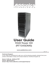
Drive Installation
Open the front panel by pressing the
front panel button on the left side
toward the right. Swing the door open
all the way, then insert drives SATA
connector first, label side up as
shown, until they stop. Drives should
slide into the enclosure easily, do not
force them. Snap the cover closed
over the drives.
Hot Swapping
The cabinet itself may be disconnected from its SATA host, or both drives
may be ejected from the unit without shutting down the operating system.
However, the SATA controller connected to the unit must support the Hot
Swapping feature to avoid malfunction of the controller or operating system,
and any safe removal steps needed must be taken to avoid loss of data.
Port Multiplier Compatibility
When configured as a set of individual drives, the Snap-In 25 RAID will only
work with a Port Multiplier aware host. Identify your host controller and check
with its hardware manufacturer if you are unsure. Addonics offers several Port
Multiplier aware host adapters. If the SATA host adapter is not port multiplier
aware, only the top drive may appear, or none at all.
Using identical drives for RAID 0 or RAID 1 is strongly recommended. Creat-
ing a RAID 0 or 1 using drives that are not all the same size will result in all
members using only as much space as the smallest member. Creating a
RAID using drives that have different performance will degrade the overall
performance of the array.

www.addonics.com Technical Support (M-F 8:30am - 6:00pm PST) Phone: 408-453-6212 Email: www.addonics.com/support/query/
Activity LED
The Activity LED glows to indicate the unit has power and blinks to indicate
activity. It does not show RAID status.
Mode Switch
The Mode switch has four settings, described in detail below:
Jbod
This setting creates a non-RAID array called LARGE.
Number of drives: 2
Unit capacity: 100% of all drives together regardless of differences in size
Fault tolerance: cannot withstand the loss of any drives without losing data.
However, some data may be recovered as long as the top drive carrying the
file system data (boot record, directory, etc.) remain online. LARGE mode is
neither a RAID nor is it a JBOD. It works by declaring the sum of all available
space of the member drives as a single unit, without striping the data. After
the first member is filled, new data is stored on the second.
RAID 1
This setting creates a Mirror Set.
Number of drives: 2
Unit capacity: size of the smallest member.
Fault tolerance: RAID 1 can withstand the loss of one drive without losing
data.
RAID 1 works by duplicating the exact same data on both drives.
RAID 0
This setting creates a Stripe Set.
Number of drives: 2
Unit capacity: size of the smallest member times two.
Fault tolerance: none - if either member is lost all data is lost.
RAID 0 “stripes” the file system across the array by placing “chunks” of data
sequentially between drives in a specific order.
Nor
This setting allows the drives to act independently of each other (“JBOD
mode”).
Number of drives: 1 or 2.
Unit capacity: N/A (100% of each individual drive)
Fault tolerance: none
JBOD mode offers both connected units to the host adapter, no RAID is
defined at all.
NOTE: JBOD mode with two drives requires a SATA controller featuring Port
Multiplier support.

Using the Mode Switch
The unit will only set up a RAID or LARGE array if it is currently set for
independent drives (Mode Switch set to “Nor”). If an array is defined and a
different array setting is desired, the unit must be powered up one time with
the Mode Switch set to “Nor” before a new array will be created. Otherwise,
simply set the switch to the desired setting and power up the unit. Leave the
Mode Switch set to the desired array type.
NOTE: Setting or modifying the mode destroys all data.
Using the JMicron RAID Manager
Windows users may install the JMicron HW RAID Manager application
located on the SATA Controller CD, or download it from
http://addonics.com/drivers/driver_list.php. In the CD, browse to Configura-
tion Utilities → JMB393.
Mac and Linux users may download those versions of the same utility from
http://addonics.com/drivers/driver_list.php under “Port Multiplier & Hub.”
The JMicron RAID Manager can be used to monitor the health status of the
RAID drives, and provide status alerts with dialog boxes and even email.
Using the JMicron RAID Manager to create or modify an array is NOT
recommended. The Mode Switch should be set to the desired type of array at
all times to prevent data loss.
www.addonics.com
Phone: 408-573-8580
Fax: 408-573-8588
Email: http://www.addonics.com/sales/query/
CONTACT US
/