Page is loading ...

M-400, M-400A Luminaires
This luminaire is designed for outdoor lighting service, and should not be used in areas of limited ventilation,
or in high ambient temperatures. Best results will be obtained if installed and maintained according to
the following recommendations.
This luminaire has been properly packed so that no parts should have been damaged during transit.
Inspect to conrm.
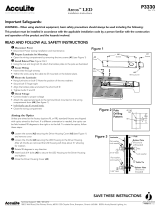
The bird shield behind slip tter clamp comes with an opening for 1 ¼ (1.660 OD) inch pipe. If a larger pipe
size is used, detach knockout to provide a larger opening. Insert pipe carefully through bird-shield and into
back of the luminaire until it hits stop which sticks down from top of housing.
Remove power module ballast door by loosening captive screw, releasing the door latch and opening door
to a vertical position. Pull out polarized disconnect plug which connects top housing wiring with ballast
door. Now grasp door securely in both hands and open door further until it comes free from hinges in top
housing. This occurs at approximately 35 degrees from vertical on pole side of hinge. In this position hinge
pins will easily slide upward out of their hinge cradles in top housing.
The pipe clamp accommodates only 2-inch pipe brackets for MDRA, MDCA and 1 ¼ inch thru 2 inch for
M4AC, M4AR models. If necessary, adjust 4 pipe clamp bolts such that opening is slightly larger than
pipe size being used.
The luminaire may be adjusted up or down with respect to pipe. A pad is provided on top of housing for
convenient application of hand level.
To mount, Insert pipe carefully through birdshield (if required) and into back of the luminaire until it hits
the leveling steps or stop that sticks down from the top of housing.
Hold luminaire approximately level and snug up bolts (4-5 foot-pounds). If more upward tilt of front of
luminaire is needed, rst loosen front two bolts slightly, lift luminaire and re-snug the back two. If downward
tilt is needed, reverse procedure by loosening back two bolts rst.
Once proper level has been achieved, tighten each bolt to 10-12 foot-pounds, alternating front to back
along diagonal of bracket as shown in Figure 1. If a torque wrench is not available, correct torque may
be achieved by turning bolts two to three full turns (or until bottoming occurs) past “snug position’’. This
should be done one turn at a time alternating in pattern according to Figure 1.
Turn power o before servicing
Do not touch operating luminaire
Wear safety glasses and gloves during
installation and servicing
The pipe clamp accommodates only 2-inch pipe. If necessary, adjust 4 pipe clamp bolts such that opening
is slightly larger than pipe size being used.
The luminaire may be adjusted up or down with respect to pipe. A pad is provided on top of housing for
convenient application of hand level.
To mount, Insert pipe and into back of the luminaire until it hits the stop that sticks down from the top
of housing.
Hold luminaire approximately level and snug up bolts (4-5 foot-pounds). If more upward tilt of front of
luminaire is needed, rst loosen front two bolts slightly, lift luminaire and re-snug the back two. If downward
tilt is needed, reverse procedure by loosening back two bolts rst.
Once proper level has been achieved, tighten each bolt to 10-12 foot-pounds, alternating front to back
along diagonal of bracket as shown in Figure 1. If a torque wrench is not available, correct torque may
be achieved by turning bolts two to three full turns (or until bottoming occurs) past “snug position’’. This
should be done one turn at a time alternating in pattern according to Figure 1.
g
GE
Lighting Solutions
These instructions do not purport to cover all details or variations in equipment nor to provide for every possible contingency to be met in connection with installation, operation or maintenance. Should further information
be desired or should particular problems arise which are not covered suciently for the purchaser’s purposes, the matter should be referred to GE Lighting Solutions.

The pipe clamp accommodates 1 1/4 inch through 2-inch pipe. If necessary, adjust the two pipe clamp
bolts so that opening is slightly larger than pipe size being used. Insert pipe carefully through bird shield
(if required) and into back of the luminaire until it hits the leveling steps, which stick down from the top
of housing.
By selecting dierent steps, the luminaire may be adjusted up or down with respect to pipe. A crosshair
pad is provided on top of housing for convenient application of hand level.
To mount, hold luminaire approximately level and snug up bolts (4-5 foot-pounds). If more upward tilt of
front of luminaire is needed, loosen the bolts slightly, lift luminaire and insert it to the next set of leveling
steps. If downward tilt is needed, reverse procedure by extracting the luminaire from the pipe to sit on a
more rearward set of steps.
The pipe clamp accommodates 1 ½ inch through 2-inch pipe. If necessary, adjust the two pipe clamp
bolts so that opening is slightly larger than pipe size being used, Insert pipe carefully through bird shield
(if required) and into back of the luminaire until it hits the leveling steps which stick down from the top
of housing.
By selecting dierent steps, the luminaire may be adjusted up or down with respect to pipe. A crosshair
pad is provided on top of housing for convenient application of hand level.
To mount, hold luminaire approximately level and snug up bolts (4-5 foot-pounds). If more upward tilt of
front of luminaire is needed, loosen the bolts slightly, lift luminaire and insert it to the next set of leveling
steps. If downward tilt is needed, reverse procedure by extracting the luminaire from the pipe to sit on a
more rearward set of steps.
Once the proper level has been achieved, tighten each bolt to 10-12 foot-pounds, alternating between
bolts. If a torque wrench is not available, correct torque may be achieved by turning bolts two to three
full turns (or until bottoming occurs) past their “snug position”.
NOTE: Make all electrical connections in accordance with the National Electrical Code and any
applicable local code requirements including grounding.
NOTE: Verify that supply voltage is correct by comparing it to nameplate.
When used, photoelectric (PE) receptacle should be oriented so that the word “North” is directed toward
true north. This is done by seating a PE control into receptacle, lifting upward on PE control (which will lift PE
receptacle also), and rotating them clockwise until word “North” is directed toward true north. Then lower PE
control and receptacle to rmly seat them into position. No tools are required to make this adjustment.
Alternatively, PE receptacle can be oriented before PE control is installed. This is done by lifting up on rim of
the PE receptacle and rotating it until the word “North” is directed toward true north. Lower PE receptacle
to rmly seat it in this position. Then install PE control.
To close door, swing it shut, hook latch bail over catch in top housing, and press backward on bottom of
latch until latch engages.
Open lower the single door by pulling forward on bottom of latch(s) to release it. Lower door to vertical
and install proper lamp.
To close door, swing it shut, hook latch bail over catch in top housing, and press backward on bottom of
latch until latch engages
To replace door, hold it at an angle of approximately 35 degrees from vertical and toward pole side of
hinge. Carefully insert hinge pin into hinge and allow door to hang free. Note that door is mechanically
interlocked with top housing in all positions except in the vicinity of removal location. All units: The doors
are designed to be assembled to top housing while in upright position with gravity holding hinge pin
properly in the cradle. If door is to be assembled to top housing while lying on its back, extreme care
should be taken to ensure that hinge pin is properly engaged in the cradle by lifting up rear of door.
Otherwise, breakage may occur.
In order to maintain high eciency of reectors and refractors, a regular cleaning cycle should be
established with frequency dependent on local conditions. Use a mild soap or detergent which is essentially
neutral (follow manufacturer’s recommendation; pH approximately 6 to 8), nonabrasive, and which contains
no chlorinated or aromatic hydrocarbons. Wash thoroughly, using a soft cloth, or brush if necessary. Rinse
in clean, cold water and wipe dry.
To remove door glass, rotate refractor clip 90 degrees clockwise. This allows glass to be removed. To
replace, simply reverse procedure.
To remove a plug-in starting aid, grasp it near bottom at nger grips provided and pull it straight out. To
replace, push rmly downward into position.
To remove wired starting aid, unscrew at base and gently remove wires. Take care to reinstall wires on
the same terminal positions from which they were removed.
The socket can be adjusted horizontally by loosening screws on side of support bracket, sliding socket
bracket to desired location, and retighten. To adjust in vertical direction, remove socket, place in desired
position and reinstall.
Flat MC2 200-400W HPS 2E
Flat MC3 200-400W HPS 2C
Prismatic MS2 200-400W HPS 1E+
Prismatic MS3 200-400W HPS 1F
Prismatic MC2 200-400W HPS 3E+
Prismatic MC3 200-400W HPS 2B
Prismatic SC3 200-400W HPS 2D
Clear Sag MC2 200-400W HPS 1F
Clear Sag MC3 200-400W HPS 1C
Clear Sag SC2 200-400W HPS 2F
Clear Sag SC3 200-400W HPS
2A
+ On socket setting indicated a 3/4-inch spacer bracket was added to obtain IES classication. Spacer
is provided when distribution is ordered. Contact factory if spacer is required to obtain a eld socket
setting.
HPS 200 THRU 400 WATT 510 (GLASS) MN-III 2A
HPS 200 THRU 400 WATT 510 (GLASS) MN-IV 3A
HPS 200 THRU 400 WATT 510 (GLASS) MS-II 1C
HPS 200 THRU 400 WATT 510 (GLASS) MS-III 2C
HPS 200 THRU 450 WATT FLAT GLASS MC-III A
HPS 200 THRU 450 WATT FLAT GLASS SC-II C
HPS 200 THRU 400 WATT 510 (GLASS) MS-II 1B
HPS 200 THRU 400 WATT 510 (GLASS) MS-III 2B
HPS 200 THRU 400 WATT 510 (GLASS) MN-III 2A
HPS 200 THRU 400 WATT 510 (GLASS) MN-IV 3A
HPS 200 THRU 400 WATT FLAT GLASS MC-III 1A
HPS 200 THRU 400 WATT FLAT GLASS MC-IV 1 1/2A
HPS 200 THRU 400 WATT FLAT GLASS SC-II 1 1/2C
Allow lamp/xture to cool before handling
NOTE: Use only lamps specied on nameplate. Observe lamp manufacturer’s recommendations and
restrictions on lamp operation; particularly ballast type, burning position, etc.
Open optical door by pulling forward on bottom of latch at the front of luminaire to release it. Lower door
to vertical and install proper lamp.
If the refractor/lens requires assembly to the luminaire in door, it should be installed with its front edge
under two tabs in front area of door. The latch(s) at back of the door should be turned counterclockwise
to secure refractor in place.
To close door, swing it shut, hook latch bail over catch in top housing, and press backward on bottom of
latch until latch engages.
/