INSTALLATION & MAINTENANCE INSTRUCTIONS
115 & 315 SERIES HORIZONTAL LUMINAIRES
(TWO BOLT LOCKING AND LEVELING)
American Electric Lighting a division of Acuity Lighting Group, Inc. Conyers, GA
DRAWING NO. B64877 REV E (FRONT)
©2003 ACUITY LIGHTING GROUP, INC.
PART NUMBER 058-71-64877
WARNING
DISCONNECT POWER BEFORE RELAMPING OR WIRING THE FIXTURE.
READ ALL INSTRUCTIONS COMPLETELY BEFORE STARTING INSTALLATION
TO AVOID THE RISK OF FIRE OR SHOCK, FIXTURE MUST BE INSTALLED IN COMPLIANCE WITH ALL APPLICABLE NATIONAL
AND LOCAL ELECTRICAL/BUILDING CODES. FOR CODE INTERPRETATION, CONSULT LOCAL CODE AUTHORITY
RISK OF FIRE. PRODUCT FOR OUTDOOR INSTALLATION AND USE ONLY.
WARNING
CAUTION
!
!
!
WARNING
ENSURE THAT ALL POWER IS
DISCONNECTED PRIOR TO WIRING
!
REMOVE LOWER HOUSING:
FIXTURES WITH ONE-PIECE LOWER:
Lift lower housing hinge pins out of the hinges in the upper housing.
Slide lower housing off of hinge bar.
FIXTURES WITH POWER-PAD:
Unfasten the power-pad latch screw. NOTE: The power-pad is
HEAVY, and it should not be allowed to drop free and swing.
Disconnect the two sets of electrical connectors, and then unhook
the power-pad from the hinge bar and remove it.
MOUNTING / LEVELING:
Determine the size of the mast arm. This luminaire is designed to
accommodate a mast arm from 1/1/4" to 2" dia. The luminaire is
factory set to mount to the 1-1/4" arm. To mount to a 2" arm, two
modifications must be made.
1. The rear opening must be enlarged. Knockouts are cast-in
around the rear opening for this purpose. To remove this excess
material, strike with a hammer or grasp with pliers and break off.
2. The fitter bracket must be flipped over.
(This will require the complete removal of the fitter bolts.)
STANDARD MOUNTING:
Loosen (DO NOT REMOVE) the fitter bolts. Lift the luminaire into
position in front of the mast arm such that the mast arm enters
through the opening at the rear of the luminaire and between the
fitter bracket and the luminaire housing. The mast arm should rest
against one of the cast-in steps located in this area. Using these
cast-in steps, adjust luminaire to desired mounting angle. Tighten
fitter bolts to 10-12 FT/LBS.
CAUTION
OVER-TORQUING OF FITTER CLAMP BOLTS CAN
CREATE CRACKS IN THE HOUSING CAUSING
THE FIXTURE TO FALL TO THE GROUND.
!
INPUT VOLTAGE:
If the voltage available is different from that shown on the terminal block,
consult the wiring diagram for directions.
WIRING:
Feed the supply wires through the mast arm, dress them so they do not
interfere with any components, and connect them to the proper terminals
on the terminal block. Verify that supply voltage is correct as noted on
the terminal block label. Refer to the wiring diagram and the data on the
ballast for connection information and ratings.
INSTALLING LOWER HOUSING:
FIXTURES WITH ONE-PIECE LOWER:
Insert lower housing hinge pins into the hinge cradles of the upper
housing. Swing the lower housing into position and press firmly upward
until latch snaps into position. NOTE: IT IS NEVER NECESSARY OR
ADVISABLE TO SLAM THE HOUSING CLOSED!
FIXTURES WITH POWER-PAD:
To install the ballastry power-pad, engage the hinge hook with the hinge
bar on the upper housing. Connect the two sets of electrical connectors
firmly together. (These connectors are "polarized" so they will only fit
together one way.) Swing the power-pad closed. Fasten the latch screw
until it is firmly seated, but DO NOT OVERTIGHTEN IT.
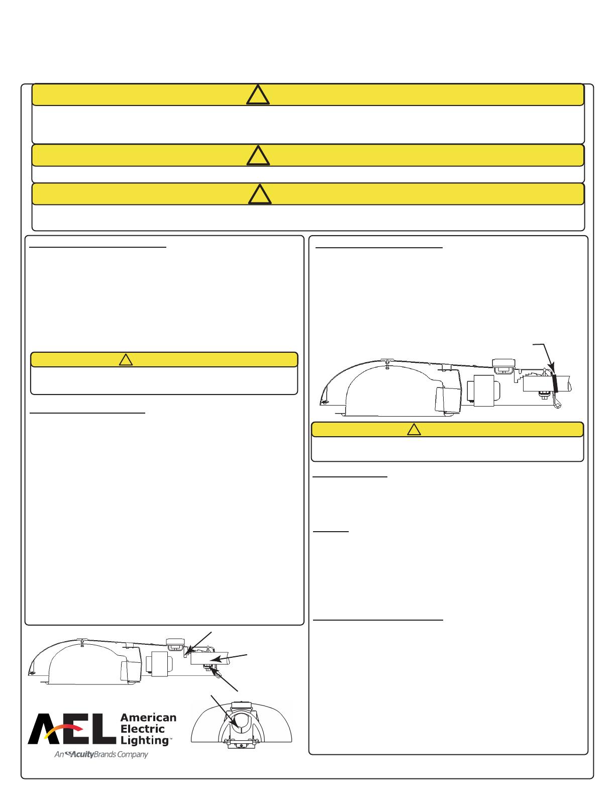
MOUNTING / LEVELING (cont.):
CSA SPECIAL REQUIREMENTS:
Slide the weather guard onto the mast arm first. Carefully fold back the
insulating barrier along the score line to expose the fitter bolts. Install
the fixture as directed in the standard mounting instructions. Once
fixture has been installed, slide the weather guard along the mast arm
until it is firmly seated against the rear of the luminaire housing. Apply
RTV sealant between the weather guard and the housing creating a
water-tight seal. Once wiring has been completed, fold the insulating
barrier back into place.
APPLY RTV BETWEEN
GUARD AND HOUSING
MAST ARM
FITTER BOLTS
LEVELING STEPS
KNOCKOUT


