EDWARDS Genesis High Candela Ceiling Strobe Installation guide
- Category
- Fire protection
- Type
- Installation guide
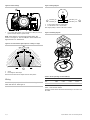
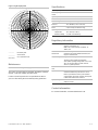
EDWARDS Genesis High Candela Ceiling Strobe is a dependable fire alarm notification appliance for indoor ceilings and walls. It offers various candela output options (95 to 177 cd) and strobe signal outputs, including public and private modes. The strobe features a synchronization circuit that complies with UL 1971 and CAN/ULC-S526 standards for enhanced coordination with compatible synchronization modules. Installation involves setting strobe signal and candela output, connecting to field wiring, mounting, and testing for proper operation.
EDWARDS Genesis High Candela Ceiling Strobe is a dependable fire alarm notification appliance for indoor ceilings and walls. It offers various candela output options (95 to 177 cd) and strobe signal outputs, including public and private modes. The strobe features a synchronization circuit that complies with UL 1971 and CAN/ULC-S526 standards for enhanced coordination with compatible synchronization modules. Installation involves setting strobe signal and candela output, connecting to field wiring, mounting, and testing for proper operation.


-
 1
1
-
 2
2
-
 3
3
-
 4
4


EDWARDS Genesis High Candela Ceiling Strobe Installation guide
- Category
- Fire protection
- Type
- Installation guide
EDWARDS Genesis High Candela Ceiling Strobe is a dependable fire alarm notification appliance for indoor ceilings and walls. It offers various candela output options (95 to 177 cd) and strobe signal outputs, including public and private modes. The strobe features a synchronization circuit that complies with UL 1971 and CAN/ULC-S526 standards for enhanced coordination with compatible synchronization modules. Installation involves setting strobe signal and candela output, connecting to field wiring, mounting, and testing for proper operation.
Ask a question and I''ll find the answer in the document
Finding information in a document is now easier with AI
Related papers
-
EDWARDS Genesis High Candela Ceiling Horn-Strobe Installation guide
-
-
-
-
-
-
-
-
-
Other documents
-
COMFORT-AIRE B-VMH24SU-1 Owner's manual
-
-
COMFORT-AIRE B-VMH30 Unit installation
-
COMFORT-AIRE VMH36SD-1-CY Installation, Operation & Maintenance Manual
-
veratron VMH 14 User manual
-
Heat Controller VMH09SC-1 User manual
-
Ingersoll-Rand Thermo King TracKing Installation guide
-
Gentex WGEC24 Series User manual
-
MGC LT-2078 Wall and Ceiling Mounted Horn User manual
-
 Gentex The Model ST/HS strobe and horn/strobe ST/HS User manual
