Page is loading ...

Document 402-0508-01
Revision B
Lobe Access Unit
User’s Guide
Models 8212 and 8214
®
Andrew Corporation
2235 First Street, Suite #115
Simi Valley, CA 93065
Sales (800) 328-2969
Technical Support (800) 8 ANDREW


© 1997 Andrew Corporation. All rights reserved.
No part of this document may be copied in any form or by any means
without the prior written consent of Andrew Corporation.
All drawings, schematics and artwork used in the manufacture of products
described herein are copyrighted. Reproduction of said drawings,
schematics and artwork or manufacture of said products without written
consent of Andrew Corporation is absolutely prohibited.
IBM is a registered trademark of International Business Machines
Corporation. Belden and Beldfoil are a registered trademark of Belden
Division of Cooper Industries, Inc.
Printed in the U.S.A.
Doc. No. 402-0508-01 Revision B – February 1997

The United States Government Federal Communications Commission has
specified that the following notice be brought to the attention of users of
this product:
Warning
This equipment generates, uses, and can radiate radio frequency
energy and if not installed and used in accordance with the
instruction manual, may cause interference with radio
communications. It has been tested and found to comply with the
limits for a Class A computing device pursuant to Subpart J of Part
15 of FCC Rules, which are designed to provide reasonable protection
against such interference when operated in a commercial
environment. Operation of this equipment in a residential area is
likely to cause interference in which case the user, at his own expense,
will be required to take whatever measures may be required to
correct the interference.

i
TABLE OF CONTENTS
CHAPTER ONE Introduction ............................ 1
1.1 Andrew LAUs ..................................... 1
1.2 Related Publications ................................ 3
CHAPTER TWO Hardware .............................. 5
2.1 Specifications ..................................... 5
Electrical ........................................ 5
Physical ......................................... 5
2.2 LEDs ........................................... 6
2.3 Connectors ....................................... 7
RJ45 Connectors ................................... 7
Data Connectors ................................... 8
2.4 Cable Specifications ............................... 10
Category 5 Cable .................................. 10
Type 3 Cable (RJ45 Connector Modules) ................ 10
Type 1 and Type 2 Cable ............................ 11
Type 1 Cable (Data Connector Modules) ................. 12
Cable Lengths .................................... 12
CHAPTER THREE Installation ............................. 13
3.1 Installation Background ............................. 13
Main Ring ...................................... 14
Backup Path ..................................... 15

ii
Lobe Access Unit User’s Guide
Adjusted Lobe Length .............................. 18
Adjusted Ring Length .............................. 18
Lobe Length ..................................... 19
Cable Type ...................................... 19
Repeaters ....................................... 19
Bridges ......................................... 19
16 Mb Token Rings ................................ 20
3.2 Calculating Distances ............................... 20
Example ........................................ 21
3.3 Distance Charts ................................... 22
4 Mb Distance Charts ............................... 23
16 Mb Distance Charts .............................. 25
3.4 LAU Installation .................................. 27
Setup Aid ....................................... 28
CHAPTER FOUR Problem Determination ................... 29
Procedure ....................................... 29
GLOSSARY ............................................ 31

1
CHAPTER ONE Introduction
1.1 Andrew LAUs
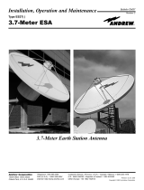
Andrew Lobe Access Units (LAUs) are typically used as Token Ring
network add-on devices, which are installed at the user’s office. They
increase the number of devices that may be attached over a single lobe
access cable to its connected MAU lobe port in the wiring closet.
Figure 1. Typical MAU/LAU configuration

Introduction
2
Lobe Access Unit User’s Guide
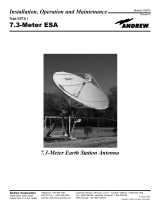
Andrew LAUs are non-powered, with status LEDs powered by the
attaching devices. They are available in four models with either data
connectors or RJ45 connectors. Model 8212 has two port channels with
either data connectors or RJ45 connectors. Model 8214 has four port
channels with either data connectors or RJ45 connectors. The four
different LAU models are shown below.
Figure 2. LAU Models 8212 and 8214

Introduction
3
1.2 Related Publications
The user’s guide for the Multistation Access Unit (MAU) to which the
Lobe Access Unit (LAU) will connect.
Andrew LAU QuickStart Guide, 402-0508-10
Andrew Token Ring Network Planning Guide, Bulletin 1565
Andrew Multistation Access Unit User’s Guide, 402-0067-01
Andrew MAUi/8700 Media Management Program User’s Guide,
402-0118-01
IBM Token-Ring Network Introduction and Planning Guide,
GA27-3677-1
IBM Token-Ring Network Installation Guide, GA27-3678
IBM Token-Ring Network Telephone Twisted-Pair Media Guide,
GA27-3714-4

Introduction
4
Lobe Access Unit User’s Guide

5
CHAPTER TWO Hardware
2.1 Specifications
The Andrew LAU’s specifications are listed below.
Electrical
Power: Andrew LAUs are non-powered
Physical
Height: Model 8212, 1.75 inches; model 8214, 1.75 inches.
Width: Model 8212, 6.5 inches; model 8214, 11.35 inches
Depth: Model 8212, 6 inches; model 8214, 6 inches
Lobe Ports: 2 or 4, RJ45 or data connectors
Main Ring Port: 1, RJ45 or data connector
Humidity: Up to 95% non-condensing
Operating Temperature: 0ºC to 55ºC
Altitude: 10,000 feet (3 km) maximum

Hardware
6
Lobe Access Unit User’s Guide
2.2 LEDs
Andrew LAUs provide a Port Channel LED for each Port Channel
connector as shown in the illustration below.
Figure 3. Port Channel LEDs
The Port Channel LED illuminates only when the device that is attached
to the channel is powered up and is connected with a working cable. The
Port Channel LED receives its power from the phantom voltage generated
by the attaching device. If the device is powered down or the cable
between the device and the port channel is broken, the Port Channel LED
will not illuminate.

Hardware
7
2.3 Connectors
Each LAU model is equipped with one Main port connector and either
two or four port channel connectors. The Main port must be connected to
a lobe port on the MAU. The attaching device must be connected to the
LAU port channel connectors.
The type of connector (RJ45 or data connector) installed on your LAU
depends on the particular Andrew LAU model that you purchased.
RJ45 Connectors
The diagram shows the transmit and receive pins in the Main and Port
Channel RJ45 connectors.
Main Port
Connector
Channel Port
Connector
Pin 1 Pin 1
Transmit
Pins 3 & 6
Receive
Pins 3 & 6
Transmit
Pins 4 & 5
Receive
Pins 4 & 5
Figure 4. RJ45 connector transmit and receive pins
RJ11 male connectors may be used instead of RJ45 male connectors on
the twisted pair cables used in the network. Both types will work in the
female connectors on the LAUs. Whether RJ45 or RJ11 male connectors
are used, the transmit and receive pins are always the four center pins in
the connector as shown in the illustration above..

Hardware
8
Lobe Access Unit User’s Guide
Important Note:
The RJ45 connector cable used with your LAUs must have at least
two twisted pairs of wire for data, no matter what cable type is used.
The cable must be wired straight-through, as shown in Figure 5. Do
not connect transmit and receive wires in the same twisted pair; the
illustration below shows how to avoid this.
Figure 5. Correct RJ45 connector and cable wiring
Data Connectors
The diagram below shows the transmit and receive pins in the Main and
Port Channel data connectors.
Figure 6. Data connector transmit and receive pins

Hardware
9
Important Note:
The data connector cable used with your LAUs must have at least two
twisted pairs of wire for data. The cable must be wired straight-
through, as shown in Figure 7. Do not connect transmit and receive
wires in the same twisted pair of wires; the illustration below shows
how to avoid this.
Figure 7. Straight-through data connector and cable wiring

Hardware
10
Lobe Access Unit User’s Guide
2.4 Cable Specifications
The following paragraphs list specifications for the different kinds of
cables which can be used with Andrew LAUs.
Category 5 Cable
This cable has been defined by the EIA/TIA as the cable of choice for
data applications up to 100 Mbps. See EIA/TIA specification #568 A/B
for building wiring recommendations.
• UTP and STP available
• 22 and 24 gauge generally available
• Impedance 100 ohms ± 15% from 512 kHz to 100 MHz
• Maximum attenuation is 67.0 dB per 1,000 at 100 MHz.
Type 3 Cable (RJ45 Connector Modules)
The UTP Type 3 (levels 3 and 4) cable used with RJ45-equipped LAUs
should be standard twisted pair telephone building wire. Recommended
wire gauge is 24 or 22 AWG, Belden 9562 or equivalent. The following
requirements should be met:
• Solid copper twisted pairs, with at least two twists per foot
• A maximum DC resistance of 28.6 ohms per 1000 feet for level
3, and 27 ohms per 1000 feet for level 4
• Characteristic impedance for level 3
—
90 to 120 ohms at 256 kHz
—
87 to 117.5 ohms at 512 kHz
—
85 to 114 ohms at 772 kHz
—
84 to 113 ohms at 1000 kHz
• Characteristic impedance for level 4 is 100 ohms at 1 – 16 MHz
• Maximum attenuation per 1000 feet for level 3
—
4.00 dB at 256 kHz
—
5.66 dB at 512 kHz
—
6.73 dB at 772 kHz
—
8.00 dB at 1000 kHz

Hardware
11
• Maximum attenuation per 1000 feet for level 4
—
5.00 dB at 1 MHz
—
22.00 dB at 16 MHz
NOTE:
Commonly available consumer telephone cable, sometimes called
“flat cable” or “silver satin,” should not be used. This type of cable
can drastically reduce the cable lengths possible in your network.
Exceptions to this are the patch cables used to connect MAUs in the
same wiring closet in 4 Mbps networks; they may be made of this
type of cable, but they should be no more than three feet in length. In
16 Mbps networks, however, silver satin of any length should not be
used.
Electrical Interference
Because Type 3 cable is unshielded, care must be taken to avoid areas of
electrical disturbance. Some examples of sources of electrical disturbance
are:
• Fluorescent lights
• Power cables
• Electric motors
• Radio transmitters.
Type 1 and Type 2 Cable
Type 1 is the IBM Cabling System term for shielded twisted pair (STP)
data cable. It consists of two twisted pairs of 22 AWG solid conductor
wire enclosed in a tinned copper braid shield, and it's covered with an
appropriate sheath. The sheath material varies according to whether or not
the cable will be used in an environmental air duct. There is also a variety
of Type 1 for outdoor use.
Type 2 cable is the same as Type 1 cable in that it has two shielded
twisted pairs of 22 AWG wire for data communication. It differs from
Type 1 in that the cable sheath also contains four twisted pairs of
unshielded 22 AWG solid conductor wire for telephones.

Hardware
12
Lobe Access Unit User’s Guide
Types 1 and 2 cable must be used with data connectors (also known as
IEEE 802.5 Medium Interface Connectors) because of the need to
terminate the cable shielding. Types 1 and 2 cable and data connectors are
available from IBM distributors and from other suppliers such as Belden
or Alpha.
Type 1 Cable (Data Connector Modules)
Standard non-plenum and plenum IBM Type 1 cables should be used with
LAUs equipped with data connectors. Recommended wire gauge is 22
AWG. The following requirements should be met:
• Solid copper in two pairs
• A maximum DC resistance of 17.4 ohms per 1000 feet
• Characteristic impedance of 150 ohms at 3-20 MHz
• Maximum attenuation per 1000 feet
—
7 dB at 4 MHz
—
14 dB at 16 MHz
• Maximum continuous current per conductor at 2.3 amp
• UL specification
—
UL Type CM (non-plenum)
—
UL Type CMP (plenum)
• Beldfoil shield type at 100% coverage
• Data connector model number ADC-205
Cable Lengths
The maximum lengths of the cables that connect the attaching devices to
the LAU port Channels and the Main port of the LAU to a MAU lobe port
depend on the data rate (4 or 16 Mbps), the type of token ring device, and
the type of port from which the cable is connected. See
Section 3.1,
Installation Background.

13
CHAPTER THREE Installation
3.1 Installation Background
This section gives general information on planning the network using
Andrew LAUs along with one or more MAUs.
Careful network planning is important before installing your MAUs,
LAUs, and attaching devices. The most important factors for the physical
part of the network are:
• Main ring length and distance between MAUs
• Length of the lobes attaching MAUs to devices, including any
adjusted lobe lengths adjustments that may need to be made to
include LAU lobe lengths.
• Number of wiring closets
• Verifying that the proper type of cable is used (see Section 2.4,
Cable Specifications.)
• Safeguarding against electrical interference, especially when
UTP cable is used.
A copy of the floor plans of the buildings that will use the token ring
network will help greatly in planning the installation. For more
information, see Section 1.2, Related Publication.
NOTE:
When using Type 3 cable with 4 Mb token rings, Andrew CTD-440C
Media Filters must be used to take full advantage of the lobe lengths
stated in this chapter. When using Type 3 cable at 16 Mb, Andrew
CTD-416C Media Filters must be used. Using another brand of media
filter may result in decreased lobe length.

Installation
14
Lobe Access Unit User’s Guide
Main Ring
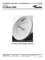
When multiple MAUs are used in a token ring network, the main ring
consists of the cable between the MAUs. The length of the main ring is
critical to proper network operation. The main ring does not include the
cable from MAUs to their LAUs or attaching devices (these cables are
called lobes).
Figure 8. Main Ring
If there is only one MAU for the entire ring, the main ring can be
considered to have no length for installation purposes.
/