
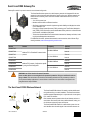
GatewayPro models for protocol conversion or web-based configuration
2.4 GHz
900 MHz
The SureCross® wireless system is a radio frequency network with integrated I/O that can
operate in most environments and eliminate the need for wiring runs. Wireless networks are
formed around a Gateway, which acts as the wireless network master device, and one or
more Nodes.
• 10 to 30V dc power input
• Modbus serial interface and Ethernet interface
• Site Survey analyzes the network’s signal strength and reliability and displays the results
on the Gateway's LCD
• Frequency Hopping Spread Spectrum (FHSS) technology and Time Division Multiple Ac-
cess (TDMA) control architecture ensure reliable data delivery within the unlicensed Indus-
trial, Scientific, and Medical (ISM) band
• Transceivers provide bidirectional communication between the Gateway and Node, includ-
ing fully acknowledged data transmission
For additional information, updated documentation, and accessories, refer to Banner Engi-
neering's website, www.bannerengineering.com/surecross.
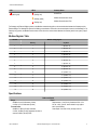
Models Feature Frequency Antenna
DX80P9T6S
Modbus/TCP or EtherNet/IP communication
protocol
900 MHz ISM Band
External
DX80P9T6W Internal
DX80P2T6S
2.4 GHz ISM Band
External
DX80P2T6W Internal
DX80P9A6S
Modbus/TCP protocol, Configuration capabil-
ity using the Web Configurator
900 MHz ISM Band
External
DX80P9A6W Internal
DX80P2A6S
2.4 GHz ISM Band
External
DX80P2A6W Internal
WARNING: Not To Be Used for Personnel Protection
Never use this device as a sensing device for personnel protection. Doing so could lead to serious
injury or death. This device does not include the self-checking redundant circuitry necessary to allow its
use in personnel safety applications. A sensor failure or malfunction can cause either an energized or de-
energized sensor output condition.
The SureCross® DX80 Wireless Network
Gateway
Node
Node
FlexPower Node
and Battery Supply Module
The SureCross® DX80 wireless I/O network provides reliable moni-
toring without wiring or conduit installation. The SureCross wireless
network operates independently or in conjunction with a host system,
PLC, and/or PC software.
Each wireless network system consists of one Gateway and one or
more Nodes. Devices ship with factory-defined discrete, analog, or a
mix of discrete and analog inputs and outputs.
The SureCross® DX80 network is a deterministic system—the net-
work identifies when the radio signal is lost and drives relevant out-
SureCross DX80 GatewayPro
P/N 131933 Rev. F 5/23/2013
0 131933 1

puts to user-defined conditions. After the radio signal is reacquired,
the network returns to normal operation.
SureCross® DX80 Gateways and Nodes
A Gateway is the master device within each radio network. Every wireless network must have one Gateway, which schedules communi-
cation traffic and controls the I/O configuration for the network, and one or more Nodes. Similar to how a gateway device on a wired
network acts as a “portal” between networks, the SureCross Gateway acts as the portal between the wireless network and the host
controller. When the Gateway, using its Modbus RTU RS-485 connection, is a Modbus slave to a Modbus RTU host controller, the wire-
less network may contain up to 47 Nodes in a single wireless network. The Gateway holds the Modbus registers of all wireless devices
within the network.
A Node is a wireless network end-point device used to provide sensing capability in a remote area or factory. The Node collects data
from sensors and communicates the data back to the Gateway. Nodes are available in a wide variety of power or input/output options.
SureCross® DX80 GatewayPro
The SureCross® DX80 GatewayPro combines the function of a SureCross® DX80 Gateway with the ability to interface to Ethernet using
Modbus/TCP or EtherNet/IP™ protocols. The GatewayPro has a serial port and an industrial Ethernet port. There are two basic models
of the GatewayPro:
• DX80P*T6*. The T6 model acts as a protocol converter only, offering the Modbus/TCP or EtherNet/IP communication protocols.
• DX80P*A6*. The A6 model includes DX80 wireless network configuration, Modbus RTU master, Modbus/TCP client/server, Script
Basic, e-mail, data logging, and trending.
Connect a host system to the GatewayPro using its industrial Ethernet connection. To connect the GatewayPro to the host system with-
out using an Ethernet switchbox/hub, some host systems may require a crossover cable. By default, the GatewayPro is configured to use
Modbus/TCP server. To use EtherNet/IP, connect the GatewayPro to a managed switch. For more information, see SureCross Wireless
I/O Product Manual or Host Configuration Manual.
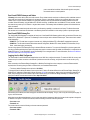
Logging into the Web Configurator
The SureCross® Pro and DX83 Ethernet Bridge devices use an XML file to configure the network. To access the XML file, use any web
browser set up for a direct connection to the Internet. If problems occur while connecting, verify the browser is not set to use a proxy
server.
When connecting to the Ethernet Bridge, GatewayPro, or MultiHop Pro directly from a host computer, a crossover Ethernet cable is
required; when connecting through a switch or Ethernet hub, use a standard Ethernet cable.
• The factory default IP address for the devices is: 192.168.0.1.
To change the device’s default IP address, first set up the host PC with an IP address different from the Ethernet Bridge, GatewayPro, or
MultiHop Pro IP addresses. (Please refer to Banner document 133116 for instructions on setting up the host computer’s network IP ad-
dress.) After changing the host’s IP address, open a web browser and log into the Ethernet Bridge, GatewayPro, or MultiHop Pro by
typing the IP address in the browser location window: http://192.168.0.1.
After entering the IP address, the home web page for the SureCross device displays. To log in, click on any tab at the top of the page. To
log out, close the browser.
Admin-level access allows administrators to set up system users and their passwords. Admin-level access is also required to change the
IP address of the system. For Admin-level access, enter the following as the user name and password:
• User name: root
• Password: sxi
For user-level access, enter the following as the user name and password.
• User name: system
• Password: admin
SureCross DX80 GatewayPro
2 www.bannerengineering.com - tel: 763-544-3164 P/N 131933 Rev. F

Setting Up Your Wireless Network
To set up and install your wireless network, follow these steps:
1. Configure the DIP switches of all devices.
2. Connect the sensors to the SureCross devices.
3. Apply power to all devices.
4. Form the wireless network by binding the Nodes to the Gateway. If the binding instructions are not included in the datasheet, refer to
the product manual for binding instructions.
5. Observe the LED behavior to verify the devices are communicating with each other.
6. Conduct a site survey between the Gateway and Nodes. If the site survey instructions are not included in this datasheet, refer to the
product manual for detailed site survey instructions.
7. Install your wireless sensor network components. If installation instructions are not included in this datasheet, refer to the product
manual for detailed installation instructions.
For additional information, including installation and setup, weatherproofing, device menu maps, troubleshooting, and a list of accesso-
ries, refer to one of the following product manuals.
• SureCross Quick Start Guide: Banner part number 128185
• SureCross Wireless I/O Network Manual: 132607
• Web Configurator Manual (used with "Pro" and DX83 models): 134421
• Host Configuration Manual 132114
Configuring the DIP Switches
Before making any changes to the DIP switch positions, disconnect the power. DIP switch changes will not be recognized if power isn't
cycled to the device.
For parameters not set via DIP switches, use the User Configuration Tool (UCT) to make configuration changes. For parameters set
using the DIP switches, the DIP switch positions override any changes made using the User Configuration Tool.
Accessing the Internal DIP Switches
To access the internal DIP switches, follow these steps:
1. Unscrew the four screws that mount the cover to the bottom housing.
2. Remove the cover from the housing without damaging the ribbon cable or the pins the cable plugs into.
3. Gently unplug the ribbon cable from the board mounted into the bottom housing.
4. Remove the black cover plate from the bottom of the device's cover.
The DIP switches are located behind the rotary dials.
After making the necessary changes to the DIP switches, place the black cover plate back into position and
gently push into place. Plug the ribbon cable in after verifying that the blocked hole lines up with the missing
pin. Mount the cover back onto the housing.
SureCross DX80 GatewayPro
P/N 131933 Rev. F www.bannerengineering.com - tel: 763-544-3164 3

DIP Switch Settings
Switches
Device Settings 1 2 3 4
Rotary dial address mode OFF*
Extended address mode ON
* Default configuration
Address Mode
The SureCross wireless devices may use one of two types of addressing modes: rotary dial addressing or extended addressing. In
rotary dial address mode, the left rotary dial establishes the network ID and the right rotary dial sets the device ID. The wireless network
is restricted to a maximum of 16 devices.
Extended address mode uses a security code to "bind" Nodes to a specific Gateway. Bound Nodes can only send and receive informa-
tion from the Gateway to which they are bound. In extended address mode, wireless networks may contain up to 48 radio devices. For
more information on extended address mode, refer to the SureCross™ Wireless I/O Network product manual.
The device ships in rotary dial address mode by default, with the DIP switch in the OFF position. To use extended address mode, change
the DIP switch to the ON position.
Wiring Your SureCross® Device
Use the following wiring diagrams to first wire the sensors and then apply power to the SureCross devices.
5-pin Euro-Style Hookup
Wiring the 5-pin Euro-style connector depends on the model and power requirements of the device. Connecting dc power to the commu-
nication pins will cause permanent damage.
Wire No. Wire Color Description
1
2
3
4
5
1 Brown 10 to 30V dc
2 White RS485 / D1 / B / +
3 Blue dc common (GND)
4 Black RS485 / D0 / A / –
5 Gray Comms Gnd
Industrial Ethernet Wiring
Use the 4-pin industrial Ethernet connection to connect the radio network to an Ethernet-based host system.
Wire No. Wire Color Description
1 White/Orange +Tx
2 White/Blue +Rx
3 Orange -Tx
4 Blue -Rx
LED Behavior for the Gateways
After powering up and binding the Gateway and its Nodes, verify all devices are communicating properly. When testing communication
between the Gateway and Node, all radios and antennas should be at least two meters apart or the communications may fail.
LED 1 LED 2 Gateway Status
(solid green)
Power ON
SureCross DX80 GatewayPro
4 www.bannerengineering.com - tel: 763-544-3164 P/N 131933 Rev. F

LED 1 LED 2 Gateway Status
(flashing red) (flashing red)
Device Error
(flashing yellow)
Modbus Communication Active
(flashing red)
Modbus Communication Error
For Gateway and Ethernet Bridge systems, active Modbus communication refers to the communication between the Gateway and the
Ethernet Bridge. For GatewayPro systems, the Modbus communication LEDs refer to the communication internal to the GatewayPro. For
Gateway only systems, the Modbus communication LEDs refer to the communication between the Gateway and its host system (if appli-
cable).
Modbus Register Table
I/O Point
Modbus Holding Register
Gateway Any Node
1 1 1 + (Node# × 16)
2 2 2 + (Node# × 16)
3 3 3 + (Node# × 16)
4 4 4 + (Node# × 16)
5 5 5 + (Node# × 16)
6 6 6 + (Node# × 16)
7 7 7 + (Node# × 16)
8 8 8 + (Node# × 16)
9 9 9 + (Node# × 16)
10 10 10 + (Node# × 16)
11 11 11 + (Node# × 16)
12 12 12 + (Node# × 16)
13 13 13 + (Node# × 16)
14 14 14 + (Node# × 16)
15 15 15 + (Node# × 16)
16 16 16 + (Node# × 16)
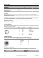
Specifications
Radio and General
Range
900 MHz: Up to 4.8 kilometers (3 miles)
2.4 GHz: Up to 3.2 kilometers (2 miles)
Transmit Power
900 MHz: 21 dBm (150 mW) conducted
2.4 GHz: 18 dBm (65 mW) conducted, less than or
equal to 20 dBm (100 mW) EIRP
Power
Requirements: +10 to 30V dc (Outside the USA: +12 to
24V dc, ±10%). (See UL section below for any applica-
ble UL specifications)
Consumption: Less than 2.9 W (120 mA) at 24V dc
SureCross DX80 GatewayPro
P/N 131933 Rev. F www.bannerengineering.com - tel: 763-544-3164 5

Radio and General
900 MHz Compliance (150 mW Radios)
FCC ID TGUDX80 - This device complies with FCC
Part 15, Subpart C, 15.247
IC: 7044A-DX8009
2.4 GHz Compliance
FCC ID UE300DX80-2400 - This device complies with
FCC Part 15, Subpart C, 15.247
ETSI/EN: In accordance with EN 300 328: V1.7.1
(2006-05)
IC: 7044A-DX8024
Spread Spectrum Technology
FHSS (Frequency Hopping Spread Spectrum)
Link Timeout
Gateway: Configurable
Node: Defined by Gateway
Radio range is with the 2 dB antenna that ships with the product.
High-gain antennas are available, but the range depends on the
environment and line of sight. To determine the range of your wire-
less network, perform a Site Survey.
Housing
Polycarbonate housing and rotary dial cover; polyester
labels; EDPM rubber cover gasket; nitrile rubber, non-
sulphur cured button covers
Weight: 0.26 kg (0.57 lbs)
Mounting: #10 or M5 (SS M5 hardware included)
Max. Tightening Torque: 0.56 N·m (5 lbf·in)
Antenna Connection
Ext. Reverse Polarity SMA, 50 Ohms
Max Tightening Torque: 0.45 N·m (4 lbf·in)
Interface
Indicators: Two bi-color LEDs
Buttons: Two
Display: Six character LCD
Wiring Access
One 5-pin Euro-style male connector and One 4-pin fe-
male industrial Ethernet connection
For European applications, power the DX80 from a Limited Power
Source as defined in EN 60950-1.
Communication and Environmental
Hardware (RS-485)
Interface: 2-wire half-duplex RS-485
Baud rates: 9.6k, 19.2k (default), or 38.4k
Data format: 8 data bits, no parity, 1 stop bit
Protocol
Modbus RTU
Modbus/TCP and EtherNet/IP
4-wire Industrial Ethernet
10/100 Mbps, full or half duplex, auto sensing
Refer to the SureCross DX80 Wireless I/O Network Product Man-
ual (p/n 132607) for installation and waterproofing instructions. Op-
erating the devices at the maximum operating conditions for exten-
ded periods can shorten the life of the device.
Rating
IEC IP67; NEMA 6; (See UL section below for any ap-
plicable UL specifications)
Operating Conditions
Temperature: −40 to +85 °C (Electronics); −20 to +80
°C (LCD)
Humidity: 95% max. relative (non-condensing)
Radiated Immunity: 10 V/m, 80-2700 MHz
(EN61000-6-2)
Shock and Vibration
IEC 68-2-6 and IEC 68-2-7
Shock: 30g, 11 millisecond half sine wave, 18 shocks
Vibration: 0.5 mm p-p, 10 to 60 Hz
Certifications
Included with Device ('Pro Models)
The following items ship with the 'Pro radios.
• BWA-HW-001: Mounting Hardware Kit, containing four M5-0.8 x 25mm SS screws, four M5-0.8 x 16mm SS screws, four M5-0.8mm
SS hex nuts, and four #8-32 x 3/4" SS bolts
• BWA-9O2-C (900 MHz) or BWA-2O2-C (2.4 GHz): Antenna, 2 dBd Omni, Rubber Swivel RP-SMA Male. (Not included with Internal
antenna models)
• Quick Start Guide (128185 for DX80 Gateways or 152653 for MultiHop models)
• MQDC1-506: 5-Euro (single ended) straight cable, 2m (Not included with FlexPower devices)
• BWA-EX2M: Ethernet crossover cable, M12 industrial/RJ45, 2 meter
SureCross DX80 GatewayPro
6 www.bannerengineering.com - tel: 763-544-3164 P/N 131933 Rev. F

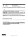
Ethernet Cables
Part No. Model No. Description
77669 BWA-E2M Ethernet cable, RSCD RJ45 440, 2M
78469 BWA-E8M Ethernet cable, RSCD RJ45 440, 8M
78467 BWA-EX2M Ethernet cable, crossover, RSCD RJ45CR 440, 2M
Use a crossover cable to connect the DX80 GatewayPro or DX83 Ethernet Bridge to a host system without using an Ethernet switchbox
or hub. When using a switchbox or hub, use a straight cable.
Warnings
Antenna Installations. Install and properly ground a qualified surge suppressor when installing a remote antenna system. Remote antenna
configurations installed without surge suppressors invalidate the manufacturer's warranty. Keep the ground wire as short as possible and make all
ground connections to a single-point ground system to ensure no ground loops are created. No surge suppressor can absorb all lightning strikes; do
not touch the SureCross® device or any equipment connected to the SureCross device during a thunderstorm.
Exporting SureCross Radios. It is our intent to fully comply with all national and regional regulations regarding radio frequency emissions. Custom-
ers who want to re-export this product to a country other than that to which it was sold must ensure the device is approved in the destina-
tion country. A list of approved countries appears in the Radio Certifications section of the product manual. The SureCross wireless products were
certified for use in these countries using the antenna that ships with the product. When using other antennas, verify you are not exceeding the transmit
power levels allowed by local governing agencies. Consult with Banner Engineering Corp. if the destination country is not on this list.
Violating Warnings. The manufacturer does not take responsibility for the violation of any warning listed in this document. Make no modifications to
this product; any modifications to this product not expressly approved by Banner Engineering could void the user’s authority to operate the product.
All specifications published in this document are subject to change; Banner reserves the right to modify product specifications or to update docu-
mentation at any time. For the most recent version of any documentation, refer to: www.bannerengineering.com. © 2006-2013 Banner Engineering
Corp. All rights reserved.
Banner Engineering Corp Limited Warranty
Banner Engineering Corp. warrants its products to be free from defects in material and workmanship for one year following the date of shipment. Banner Engineering
Corp. will repair or replace, free of charge, any product of its manufacture which, at the time it is returned to the factory, is found to have been defective during the
warranty period. This warranty does not cover damage or liability for misuse, abuse, or the improper application or installation of the Banner product.
THIS LIMITED WARRANTY IS EXCLUSIVE AND IN LIEU OF ALL OTHER WARRANTIES WHETHER EXPRESS OR IMPLIED (INCLUDING, WITHOUT LIMITATION,
ANY WARRANTY OF MERCHANTABILITY OR FITNESS FOR A PARTICULAR PURPOSE), AND WHETHER ARISING UNDER COURSE OF PERFORMANCE,
COURSE OF DEALING OR TRADE USAGE.
This Warranty is exclusive and limited to repair or, at the discretion of Banner Engineering Corp., replacement. IN NO EVENT SHALL BANNER ENGINEERING CORP.
BE LIABLE TO BUYER OR ANY OTHER PERSON OR ENTITY FOR ANY EXTRA COSTS, EXPENSES, LOSSES, LOSS OF PROFITS, OR ANY INCIDENTAL,
CONSEQUENTIAL OR SPECIAL DAMAGES RESULTING FROM ANY PRODUCT DEFECT OR FROM THE USE OR INABILITY TO USE THE PRODUCT, WHETH-
ER ARISING IN CONTRACT OR WARRANTY, STATUTE, TORT, STRICT LIABILITY, NEGLIGENCE, OR OTHERWISE.
Banner Engineering Corp. reserves the right to change, modify or improve the design of the product without assuming any obligations or liabilities relating to any product
previously manufactured by Banner Engineering Corp.
SureCross DX80 GatewayPro
www.bannerengineering.com - tel: 763-544-3164
-
 1
1
-
 2
2
-
 3
3
-
 4
4
-
 5
5
-
 6
6
-
 7
7


Banner SureCross DX80P2A6S GatewayPro Quick start guide
- Type
- Quick start guide
Ask a question and I''ll find the answer in the document
Finding information in a document is now easier with AI
Related papers
-
Banner SureCross DX80P2A6W GatewayPro User manual
-
Banner SureCross Performance GatewayPro Series User manual
-
-
-
-
-
-
-
-
Other documents
-
LumenRadio W-Modbus User manual
-
-
-
 ETS-Lindgren 3164-07 Owner's manual
-
AMP FSR1 Quick start guide
-
Aceinna eB2110 User manual
-
Munters RS Product information
-
Omron E8M-A1-S User manual
-
Takstar E8M User manual
-
SYNAPSE Bridge 485 Wireless Sensor Interface Installation guide
