Toro 60in Chute Gate Kit, Z Master 4000 Series Riding Mower Installation guide
- Category
- Lawnmowers
- Type
- Installation guide
This manual is also suitable for
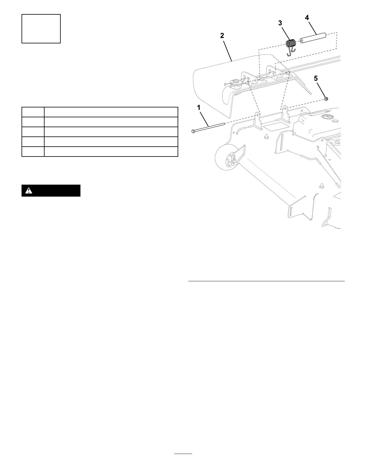
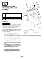
Toro 60in Chute Gate Kit, Z Master 4000 Series Riding Mower allows you to easily switch between side discharge and mulching or bagging with its innovative gate system, providing versatility for different mowing conditions and preferences. The kit includes a side discharge chute with gate, control box, cables, and mounting hardware for seamless installation. Additionally, the chute gate can be conveniently opened and closed from the operator's seat, enhancing user-friendliness.
Toro 60in Chute Gate Kit, Z Master 4000 Series Riding Mower allows you to easily switch between side discharge and mulching or bagging with its innovative gate system, providing versatility for different mowing conditions and preferences. The kit includes a side discharge chute with gate, control box, cables, and mounting hardware for seamless installation. Additionally, the chute gate can be conveniently opened and closed from the operator's seat, enhancing user-friendliness.


-
 1
1
-
 2
2
-
 3
3
-
 4
4
-
 5
5
-
 6
6
-
 7
7
-
 8
8


Toro 60in Chute Gate Kit, Z Master 4000 Series Riding Mower Installation guide
- Category
- Lawnmowers
- Type
- Installation guide
- This manual is also suitable for
Toro 60in Chute Gate Kit, Z Master 4000 Series Riding Mower allows you to easily switch between side discharge and mulching or bagging with its innovative gate system, providing versatility for different mowing conditions and preferences. The kit includes a side discharge chute with gate, control box, cables, and mounting hardware for seamless installation. Additionally, the chute gate can be conveniently opened and closed from the operator's seat, enhancing user-friendliness.
Ask a question and I''ll find the answer in the document
Finding information in a document is now easier with AI
Related papers
-
Toro Chute Gate Kit, 34in and 40in Mowers for Z300 Series Z Master Riding Mowers Installation guide
-
-
Toro Bagger Kit, Z Master 4000 Series Riding Mower User manual
-
-
-
-
-
-
-