Toro 48in Chute Gate Kit, Z Master 4000 Series Riding Mower Installation guide

Category
Lawnmowers
Type
Installation guide
FormNo.3444-969RevA
ChuteGateKit
ZMaster
®
4000SeriesRidingMower
ModelNo.144-2688
ModelNo.144-6571
ModelNo.144-6572
InstallationInstructions
Safety
SafetyandInstructional
Decals
Safetydecalsandinstructionsare
easilyvisibletotheoperatorandare
locatednearanyareaofpotential
danger.Replaceanydecalthatis
damagedormissing.
decal99-8936
99-8936
1.Machinespeed4.Neutral
2.Fast5.Reverse
3.Slow
decal144-6593
144-6593
1.Chutegate3.Openthechutegate.
2.Closethechutegate.4.ReadtheOperator’s
Manual.
©2021—TheToro®Company
8111LyndaleAvenueSouth
Bloomington,MN55420
Registeratwww.Toro.com.
OriginalInstructions(EN)
PrintedintheUSA
AllRightsReserved
*3444-969*
Installation
LooseParts
Usethechartbelowtoverifythatallpartshavebeenshipped.
ProcedureDescription
Qty.
Use
1
Nopartsrequired
Preparethemachine.
2
Nopartsrequired
Removetheexistingsidedischarge
chute.
Dischargebafe
1
Baggerbafe
1
Carriagebolt(3/8x7/8inch)
4
Locknut(3/8inch)
4
Carriagebolt(5/16x7/8inch)
1
3
Locknut(5/16inch)
1
Preparethemowerdeck.
Sidedischargechutewithgate
1
Hex-headbolt(5/16x7-1/2inches)
1
Locknut(5/16inch)
1
Spacer
1
4
Spring
1
Installthesidedischargechutewiththe
gate.
Controlboxassembly
1
Carriagebolt(3/8x7/8inch)
2
Locknut(3/8inch)
2
Cabletie
3
5
Adhesivecabletie1
Installthecontrolbox.
Note:Determinetheleftandrightsidesofthemachinefromthenormaloperatingposition.
1
PreparingtheMachine
NoPartsRequired
Procedure
1.Parkthemachineonalevelsurface.
2.Disengagetheblade-controlswitch.
3.Movethemotion-controlleversoutwardtotheNEUTRAL-LOCKposition.
4.Engagetheparkingbrake.
5.Shutofftheengineandremovethekey.
2
2
RemovingtheExistingSide
DischargeChute
NoPartsRequired
Procedure
Removethebolt,spring,spacer,andlocknutsecuring
thedischargechuteandremovethedischargechute
(Figure1).
g348922
Figure1
1.Bolt
4.Spacer
2.Dischargechute5.Locknut
3.Spring
3
PreparingtheMowerDeck
Partsneededforthisprocedure:
1
Dischargebafe
1
Baggerbafe
4
Carriagebolt(3/8x7/8inch)
4
Locknut(3/8inch)
1
Carriagebolt(5/16x7/8inch)
1
Locknut(5/16inch)
Procedure
1.Removetheexistingdischargebafe,2carriage
bolts,and2locknuts(Figure2).
Discardthefasteners.
g348992
Figure2
1.Carriagebolt
3.Locknut
2.Existingdischargebafe
3
2.Removethe2carriageboltsand2locknutsat
thefrontofthemowerdeck(Figure3).
Discardthefasteners.
g348993
Figure3
1.Locknut
2.Carriagebolt
3.Installthebaggerbafetothemowerdeckand
deckbumperusing2carriagebolts(3/8x7/8
inch),2locknuts(3/8inch),1carriagebolt(5/16
x7/8inch),and1locknut(5/16inch)asshown
inFigure4andFigure5.
g348990
Figure4
60-inchdeckshown
1.Locknut(3/8inch)3.Carriagebolt(3/8x7/8
inch)
2.Baggerbafe
g348994
Figure5
1.Baggerbafe3.Carriagebolt(5/16x7/8
inch)
2.Locknut(5/16inch)
4.Deckbumper
4
4.Installthenewdischargebafeusing2carriage
bolts(3/8x7/8inch)and2locknuts(3/8inch)
asshowninFigure6.
g348991
Figure6
1.Carriagebolt(3/8x7/8
inch)
3.Locknut(3/8inch)
2.Newdischargebafe
5
4
InstallingtheSide
DischargeChutewith
theGate
Partsneededforthisprocedure:
1
Sidedischargechutewithgate
1
Hex-headbolt(5/16x7-1/2inches)
1
Locknut(5/16inch)
1
Spacer
1
Spring
Procedure
WARNING
Anuncovereddischargeopeningcouldallow
themachinetothrowobjectstowardyouor
bystanders,resultinginseriousinjury.Also,
contactwiththebladecouldoccur.
Neveroperatethemachineunlessyouinstall
amulchplate,dischargedeector,orgrass
collectionsystem.
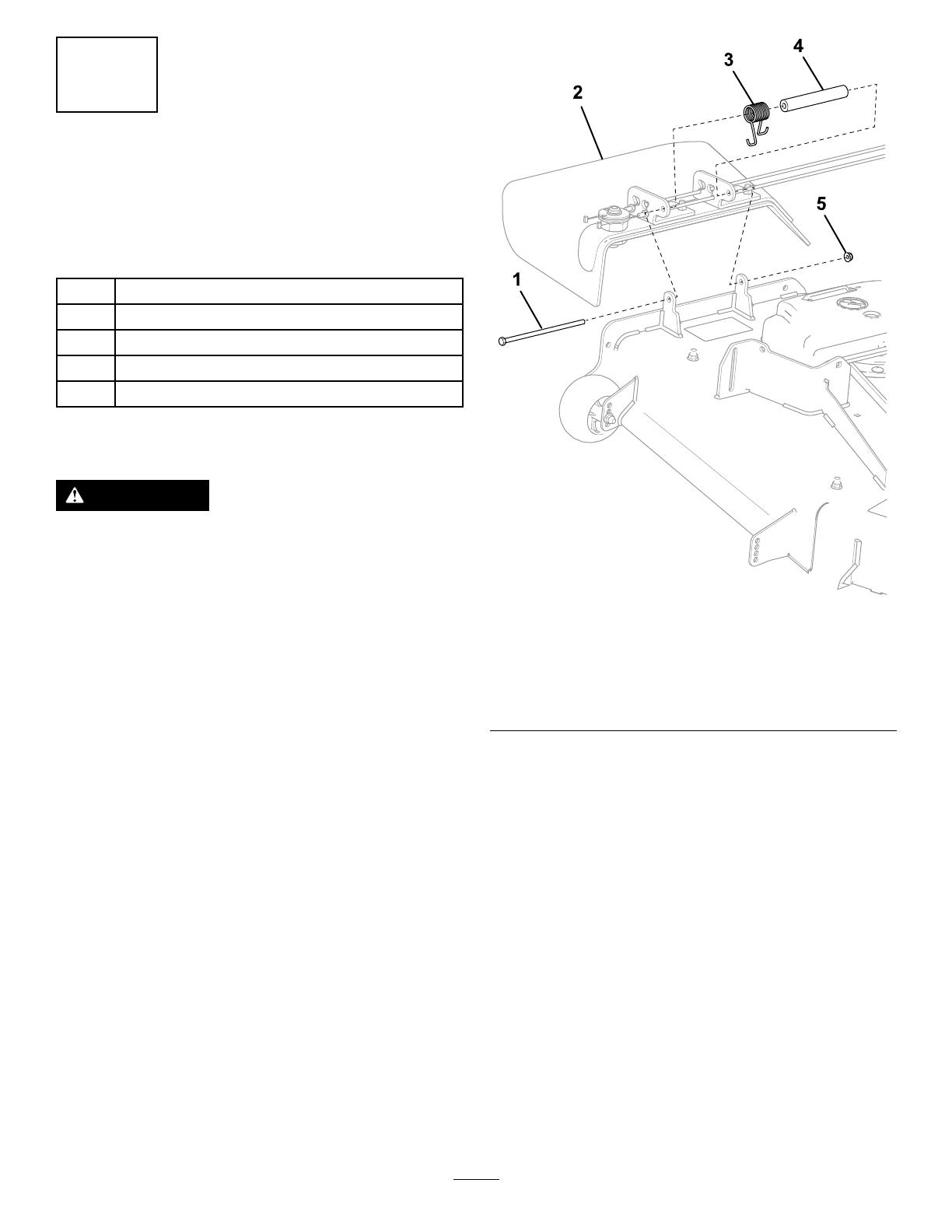
1.Placethenewspacerandspringontothe
dischargechute(Figure7).
Place1endofthespringbehindthedeckedge.
Note:Ensurethattheendofthespringis
installedbehindthedeckedgebeforeinstalling
thehex-headbolt(5/16x7-1/2inches).
2.Installhex-headbolt(5/16x7-1/2inches)and
locknut(5/16inch)asshowninFigure7.
Placetheendofthespringaroundthedischarge
chute.
3.Tightenthelocknut(5/16inch)untiltheendof
thehex-headbolt(5/16x7-1/2inches)isush
withtheendofthelocknut(5/16inch).
Donotovertightenthelocknut.
Important:Thedischargechutemust
beabletolowerdownintoposition.Lift
thechuteuptotestthatitlowersintothe
fully-downposition.
g349056
Figure7
1.Hex-headbolt(5/16x
7-1/2inches)
4.Spacer
2.Dischargechute
5.Locknut(5/16inch)
3.Spring
6
5
InstallingtheControlBox
Partsneededforthisprocedure:
1
Controlboxassembly
2
Carriagebolt(3/8x7/8inch)
2
Locknut(3/8inch)
3
Cabletie
1Adhesivecabletie
Procedure
1.Routethecablesbetweenthecontrolbox
anddischargechuteasshowninFigure8to
avoiddamagingthecablesthroughtheentire
height-of-cutrange.
Important:Ensurethatyouroutethecables
awayfromthefrontofthedeck-liftpedalas
showninFigure8sothatyoudonotdamage
thecables.
g349011
Figure8
2.Removetheself-threadingscrewfromtheright
motion-controlcover(Figure9).
Retaintheself-threadingscrew.
g349074
Figure9
1.Rightmotion-controlcover
2.Self-threadingscrew
3.Removethe4shoulderscrewssecuringthe
rightsidepod(Figure10).
Retainthe4shoulderscrewsandrightsidepod
forlaterinstallation.
4.Removetherightsidepod(Figure10).
g345495
Figure10
1.Rightsidepod
2.Shoulderscrew
7
5.Securethecontrolboxtotherightmotion-control
coverusing2carriagebolts(3/8x7/8inch)and
2locknuts(3/8inch)asshowninFigure11.
g349073
Figure11
1.Locknut(3/8inch)3.Controlbox
2.Carriagebolt(3/8x7/8
inch)
6.Installthepreviouslyremovedself-threading
screwtotherightmotion-controlcover(Figure
9).
7.Securetherightsidepodusingthepreviously
removed4shoulderscrews(Figure10).
8.Installtheadhesivebackplasticmountona
smooth,cleansurface.
Threadthecabletiethroughtheplasticmount
andsecurethecableswiththecabletie.
9.Slowlymovethemowerdeckthroughthe
height-of-cutrangetoensurethatthecablesdo
notstretchorkinkwhenyouareoperatingthe
machine.
8
  • Page 1 1
  • Page 2 2
  • Page 3 3
  • Page 4 4
  • Page 5 5
  • Page 6 6
  • Page 7 7
  • Page 8 8

Toro 48in Chute Gate Kit, Z Master 4000 Series Riding Mower Installation guide

Category
Lawnmowers
Type
Installation guide

Ask a question and I''ll find the answer in the document

Finding information in a document is now easier with AI