
AIT Drive
4-679-249-17(1)
2003 Sony Corporation
AIT-4 TAPE DRIVE
AITi520
AIT-3 Ex TAPE DRIVE
AITi390
AIT-3 TAPE DRIVE
AITi260
AIT-2 TAPE DRIVE
AITi130
AIT-1 TAPE DRIVE
AITi90
User’s Guide

2
This document contains proprietary
information which is protected by
copyright.
All rights reserved. No part of this
document may be photocopied,
reproduced or translated to another
language without prior written consent
of Sony.
The information contained in this
document is subject to change without
notice.
SONY MAKES NO WARRANTY
OF ANY KIND WITH REGARD TO
THIS DOCUMENT.
Sony shall not be liable for errors
contained herein, indirect, special,
incidental or consequential damages in
connection with the furnishing,
performance or use of this document.
Your AITi90, AITi130 is assigned a
Model No. ATDNA2 for regulatory
compliance certifications.
Your AITi260 is assigned a Model No.
ATDNA3 for regulatory compliance
certifications.
Your AITi390, AITi520 is assigned a
Model No. ATDNA4 for regulatory
compliance certifications.
The number is indicated on the model
number label on your drive along with
the rated voltage and current.
VORSICHT
Für Kunden in Deutschland
Diese Ausrüstung erfüllt die
Europäischen EMC-Bestimmungen für
die Verwendung in folgender /
folgenden Umgebung(en):
• Wohngegenden
• Gewerbegebiete
• Leichtindustriegebiete
(Diese Ausrüstung erfüllt die
Bestimmungen der Norm EN55022,
Klasse B.)

3
IMPORTANT SAFEGUARDS
For your protection, please read these
safety instructions completely before
operating the appliance, and keep this
manual for future reference.
Carefully observe all warnings,
precautions and instructions on the
appliance, or the one described in the
operating instructions and adhere to
them.
USE
Power Sources – This unit should be
operated only from the type of power
source indicated on the marking label.
If you are not sure of the type of
electrical power, consult your dealer or
local power company.
For the unit with a three-wire
grounding type ac plug:
If you are unable to insert the plug into
the outlet, contact your electrician to
have a suitable plug installed. Do not
defeat the safety purpose of the
grounding plug.
AC Power cord: (for AC mains
operating unit only)
The AC power cord should have
appropriate safety approvals or
marking for the country in which the
equipment will be used. Consult your
dealer or local power company.
Cleaning – Unplug the unit from the
wall outlet before cleaning or
polishing it. Do not use liquid
cleaners or aerosol cleaners.
Use a cloth lightly dampened with
water for cleaning the exterior of the
unit.
Object and Liquid Entry – Never
push objects of any kind into the unit
through openings as they may touch
dangerous voltage points or short out
parts that could result in a fire or
electric shock. Never spill liquid of
any kind on the unit.

4
INSTALLATION
Water and Moisture – Do not use
power-line operated units near water -
for example, near a bathtub,
washbowl, kitchen sink, or laundry
tub, in a wet basement, or near a
swimming pool, etc.
Power-Cord Protection – Route the
power cord so that it is not likely to be
walked on or pinched by items placed
upon or against them, paying
particular attention to the plugs,
receptacles, and the point where the
cord exits from the appliance.
Accessories – Do not place the unit on
an unstable cart, stand, tripod, bracket,
or table. The unit may fall, causing
serious injury to a child or an adult,
and serious damage to the unit. Use
only a cart stand tripod, bracket, or
table recommended by the
manufacturer.
Ventilation – The slots and openings
in the cabinet are provided for
necessary ventilation. To ensure
reliable operation of the unit, and to
protect it from overheating, these slots
and openings must never be blocked or
covered.
• Never cover the slots and openings
with a cloth or other materials.
• Never block the slots and openings
by placing the unit on a bed, sofa,
rug or other similar surface.
• Never place the unit in a confined
space, such as a bookcase, or built-
in cabinet, unless proper ventilation
is provided.
SERVICE
Damage Requiring Service – Unplug
the unit from the wall outlet and refer
servicing to qualified service
personnel under the following
conditions:
• When the power cord or plug is
damaged or frayed.
• If liquid has been spilled or objects
have fallen into the unit.
• If the unit has been exposed to rain
or water.
• If the unit has been subject to
excessive shock by being dropped,
or the cabinet has been damaged.
• If the unit does not operate normally
when following the operating
instructions. Adjust only those
controls that are specified in the
operating instructions. Improper
adjustment of other controls may
result in damage and will often
require extensive work by a
qualified technician to restore the
unit to normal operation.
• When the unit exhibits a distinct
change in performance - this
indicates a need for service.
Servicing – Do not attempt to service
the unit yourself as opening or
removing covers may expose you to
dangerous voltage or other hazards.
Refer to all servicing to qualified
service personnel.

5
Contents
Overview .................................................................................................................. 6
Introduction .............................................................................................................. 7
About AIT Drives ............................................................................................ 7
Precautions .....................................................................................................10
Installation ..............................................................................................................12
SCSI Connection/Setting the SCSI ID ...........................................................12
Option Switches (DIP Switch) .......................................................................13
Mounting Holes..............................................................................................17
Reconfiguring from 5.25" Model to 3.5" Model............................................19
Orientation......................................................................................................20
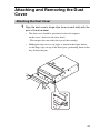
Attaching and Removing the Dust Cover ...............................................................21
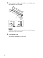
Attaching the Dust Cover ............................................................................... 21
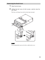
Removing the Dust Cover .............................................................................. 23
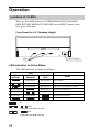
Operation ................................................................................................................24
Location of 3 LEDs ........................................................................................ 24
Drive Operation..............................................................................................25
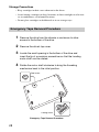
Emergency Tape Removal Procedure ............................................................ 28
WORM Function ....................................................................................................30
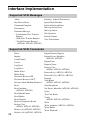
Interface Implementation........................................................................................ 32
Supported SCSI Messages .............................................................................32
Supported SCSI Commands........................................................................... 32
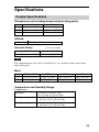
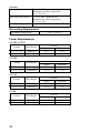
Specifications .........................................................................................................33
Product Specifications....................................................................................33
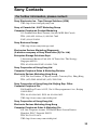
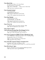
Sony Contacts ......................................................................................................... 35
• Sony cannot accept liability for data written to cartridges lost as a result of using this product.
• Sony bears no responsibility for any financial damages, lost profits, or claims made by third
parties arising from the use of this product.

6
Overview
The Sony AITi520, AITi390, AITi260, AITi130 and AITi90 drives are
high capacity data storage devices using Advanced Intelligent Tape (AIT)
technology. The AITi260, AITi130 and AITi90 drives achieve high data
reliability through third-level Error Correction Code (second-level Error
Correction Code for the AITi520 and AITi390).
The Sony AITi520, AITi390, AITi260, AITi130 and AITi90 drives store
data on tape using standard formats called AIT (Advanced Intelligent Tape)
and ALDC formats.

7
Introduction
About AIT Drives
The AITi520 is an internal AIT drive unit that uses data cartridges
conforming to the AIT-4 format. The AITi390 is an internal AIT drive unit
that uses data cartridges conforming to the AIT-3 Ex format. The AITi260
is an internal AIT drive unit that uses data cartridges conforming to the
AIT-3 format. The AITi130 is an internal AIT drive unit that uses data
cartridges conforming to the AIT-2 format. The AITi90 is an internal AIT
drive unit that uses data cartridges conforming to the AIT-1 format. The
AITi520 supports AIT-4 format. The AITi390 supports AIT-1 (Read only),
AIT-2 (Read only), AIT-3 and AIT-3 Ex formats. The AITi260 supports
AIT-1, AIT-2 and AIT-3 formats. The AITi130 supports AIT-1 and AIT-2
formats. The AITi90 supports only AIT-1 format.
Features
The AIT Drive Unit AITi520 has the following features:
• Supports reading and writing to data cartridges conforming to the AIT-4
format.
• The second-level error correction code guarantees high data reliability
writing to data cartridges conforming to the AIT-4 format.
• Data compression provides 520 gigabytes of storage on SDX4-200C.
*1
The native capacity is 200 gigabytes of storage on SDX4-200C.
• Stored data are automatically checked for compression.
• Ultra 160 SCSI LVD/SE interface is fully supported for host computer
access.
*1
This is assuming 2.6 : 1 compression ratio.
The degree of data compression attained while recording data varies according to
system environment and data type.

8
The AIT Drive Unit AITi390 has the following features:
• Supports reading and writing to data cartridges conforming to the AIT-3
and AIT-3 Ex formats.
• Supports reading from data cartridges conforming to the AIT-1 and
AIT-2 formats.
• The second-level error correction code guarantees high data reliability
writing to data cartridges conforming to the AIT-3 Ex format.
• The third-level error correction code guarantees high data reliability
writing to data cartridges conforming to the AIT-1, AIT-2 and AIT-3
formats.
• Data compression provides 390 gigabytes of storage on SDX3X-150C.
*1
The native capacity is 150 gigabytes of storage on SDX3X-150C.
• Stored data are automatically checked for compression.
• Ultra 160 SCSI LVD/SE interface is fully supported for host computer
access.
The AIT Drive Unit AITi260 has the following features:
• Supports reading and writing to data cartridges conforming to the AIT-1,
AIT-2 and AIT-3 formats.
• The third-level error correction code guarantees high data reliability.
• Data compression provides 260 gigabytes of storage on SDX3-100C.
*1
The native capacity is 100 gigabytes of storage on SDX3-100C.
• Stored data are automatically checked for compression.
• Ultra 160 SCSI LVD/SE interface is fully supported for host computer
access.
The AIT Drive Unit AITi130 has the following features:
• Supports reading and writing to data cartridges conforming to the AIT-1
and AIT-2 formats.
• The third-level error correction code guarantees high data reliability.
• Data compression provides 130 gigabytes of storage on SDX2-50C.
*1
The native capacity is 50 gigabytes of storage on SDX2-50C.
• Stored data are automatically checked for compression.
• Wide Ultra SCSI LVD/SE interface is fully supported for host computer
access.
*1
This is assuming 2.6 : 1 compression ratio.
The degree of data compression attained while recording data varies according to
system environment and data type.

9
The AIT Drive Unit AITi90 has the following features:
• Supports reading and writing to data cartridges conforming to the AIT-1
format.
• The third-level error correction code guarantees high data reliability.
• Data compression provides 91 gigabytes of storage on SDX1-35C.
*1
The native capacity is 35 gigabytes of storage on SDX1-35C.
• Stored data are automatically checked for compression.
• Wide Ultra SCSI LVD/SE interface is fully supported for host computer
access.
*1
This is assuming 2.6 : 1 compression ratio.
The degree of data compression attained while recording data varies according to
system environment and data type.

10
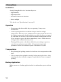
Precautions
Installation
Avoid placing the drive in a location subject to:
– high humidity
– high temperature
– mechanical shock and vibration
– direct sunlight
*
For details, see “Specifications” on page 33.
Operation
• Do not move the drives while they are operating. It may cause
malfunctions.
• Avoid exposing the drives to sudden changes from low to high
temperatures. This may cause condensation to collect inside the drives. If
the ambient temperature should suddenly rise while the drives are turned
on, turn them off and wait at least one hour before turning them back on.
If you attempt to operate the drives immediately after a sudden increase
in temperature, malfunctions may occur.
• Turning off the power to the drives while they are writing to tape may
cause the tape to become unreadable. All previously negotiated
parameters will be lost, whenever power to the drives is cycled.
Transportation
• Keep the original packing materials to facilitate safe transportation of the
drive.
• Always remove the tape/media cartridge before moving the drive. After
removing the drive from the computer, repack the drive into its original
packing.
Backup Application
Make sure to use a backup application that is confirmed to operate with an
ISV.

11
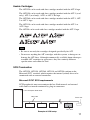
Usable Cartridges
The AITi520 can be used with data cartridges marked with the AIT-4 logo.
The AITi390 can be used with data cartridges marked with the AIT-1 (read
only), AIT-2 (read only), AIT-3 or AIT-3 Ex logo.
The AITi260 can be used with data cartridges marked with the AIT-1, AIT-
2 or AIT-3 logo.
The AITi130 can be used with data cartridges marked with the AIT-1 or
AIT-2 logo.
The AITi90 can be used with data cartridges marked with the AIT-1 logo.
Note
• Be sure to use only the cartridges designed specifically for AIT.
• Do not use anything but AIT cartridges with this system, as doing so can
damage the AIT drive. Although commercially available 8mm videotapes
resemble AIT cartridges in appearance, they have entirely different
specifications and cannot be used.
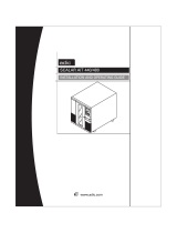
SCSI Termination
The AITi520, AITi390, AITi260, AITi130 and AITi90 conform to the
Microsoft PC97 standard, which requires the internal (naked) drive to be
terminated with an external terminator.
Microsoft PC97 SCSI requirements
SCSI peripherals must not terminate the bus. Both internal and external
cable ends are instead terminated by plug-in connectors.
Terminato
r
68p cable
Host Computer Wide SCSI
This drive
Example of SCSI setup

12
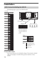
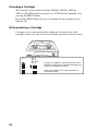
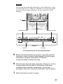
Installation
SCSI Connection/Setting the SCSI ID
The following figures apply to the AITi520 model.
SCSI 68pin Connector
5 V
Power Connector
1234
GND GND 12 V
Disable
Enable
Parity
Note :
=
=
= CLOSED/Jumper
Don’
t care
OPEN/Jumper not
installed
Parity Disable
No Connection
SCSI ID 3
SCSI ID 2
SCSI ID 1
SCSI ID 0
Jumpers
SCSI ID
SCSI ID
0
1
2
3
4
5
6
7
8
9
10
1
1
12
13
14
15
2
1
0
P.D.
N.C.
3
Parity Disable Jumper
Parity check function can be disabled by Jumper. Parity check is disabled
while left end jumper is installed. Parity generate function is always
enabled.

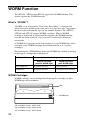
13
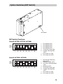
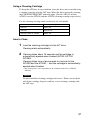
Option Switches (DIP Switch)
DIP Switch Positions
Default (AITi90, AITi130, AITi260)
ON
OFF
12345678
1 Drive Mode (OFF)
2 Drive Mode (OFF)
3 Drive Mode (OFF)
4 Drive Mode (OFF)
5 Terminator Power (ON)
6 Periodic Cleaning Req
(OFF)
7 DC Control (1) (ON)
8 DC Control (2) (OFF)
DIP Switch
Default (AITi390, AITi520)
1 DR (Disaster Recovery)
Mode (OFF)
2 Emulation Mode (OFF)
3 AIT Library Interface Mode
(ON)
4 Reserved (OFF)
5 Terminator Power (ON)
6 Periodic Cleaning Req
(OFF)
7 DC Control (1) (ON)
8 DC Control (2) (OFF)
ON
OFF
12345678

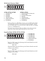
14
DR (Disaster Recovery
*
) Mode
ON
OFF
12345678
*
In Disaster Recovery (DR) Mode, the drive enters the DR Standby Mode
15 seconds after you insert a write-protected tape into the drive, and all
the drive LEDs blink. If you restart the drive while the LEDs are blinking,
it starts as a CD-ROM device.
For details about the Disaster Recovery Mode, refer to the instruction
manual that came with the application software you are using.
Emulation Mode
*
(AITi90, AITi130, AITi260)
ON
OFF
12345678
*
Emulation Mode returns the following in the Product Identification field
of Inquiry of the AITi260.
SDX-700C
*
Emulation Mode returns the following in the Product Identification field
of Inquiry of the AITi130.
SDX-500C
*
Emulation Mode returns the following in the Product Identification field
of Inquiry of the AITi90.
SDX-400C
AITi90, AITi130, AITi260
1 Drive Mode (ON)
2 Drive Mode
3 Drive Mode
4 Drive Mode
5 Terminator Power
6 Periodic Cleaning Req
7 DC Control (1)
8 DC Control (2)
1 Drive Mode (ON)
2 Drive Mode (ON)
3 Drive Mode (ON)
4 Drive Mode (ON)
5 Terminator Power
6 Periodic Cleaning Req
7 DC Control (1)
8 DC Control (2)
AITi390, AITi520
1 DR (Disaster Recovery) Mode (ON)
2 Emulation Mode
3 AIT Library Interface Mode
4 Reserved
5 Terminator Power
6 Periodic Cleaning Req
7 DC Control (1)
8 DC Control (2)

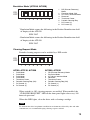
15
AITi90, AITi130, AITi260
1 Drive Mode
2 Drive Mode
3 Drive Mode
4 Drive Mode
5 Terminator Power
6 Periodic Cleaning Req (ON)
7 DC Control (1)
8 DC Control (2)
Emulation Mode
*
(AITi390, AITi520)
ON
OFF
12345678
*
Emulation Mode returns the following in the Product Identification field
of Inquiry of the AITi520.
SDX-700C
*
Emulation Mode returns the following in the Product Identification field
of Inquiry of the AITi390.
SDX-700C
Cleaning Request Mode
Periodic cleaning requests can be enabled by a DIP switch.
ON
OFF
12345678
When switch 6 is ON, cleaning requests are enabled. When enabled, the
“CLEANING REQUEST” LED on the front panel lights after every 100
hours of operation.
When this LED lights, clean the drive with a cleaning cartridge.
Note
To maintain the drive in optimum condition in environments affected by dust and other
contaminants, we recommend keeping cleaning requests enabled.
1 DR (Disaster Recovery)
Mode
2 Emulation Mode (ON)
3 AIT Library Interface Mode
4 Reserved
5 Terminator Power
6 Periodic Cleaning Req
7 DC Control (1)
8 DC Control (2)
AITi390, AITi520
1 DR (Disaster Recovery) Mode
2 Emulation Mode
3 AIT Library Interface Mode
4 Reserved
5 Terminator Power
6 Periodic Cleaning Req (ON)
7 DC Control (1)
8 DC Control (2)

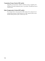
16
Terminator Power Control DIP switch
This DIP switch determines whether terminator power is supplied to the
SCSI bus. To enable terminator power, set position 5 [Terminator Power]
switch to ON.
Data Compression Control DIP switch
Data compression can be selected by DIP switches. Data compression is
enabled when position 7 [DC Control (1)] is ON. Control by host can be
disabled when position 8 [DC Control (2)] is ON.

17
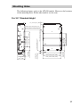
Mounting Holes
The following figures apply to the AITi520 models. However, the locations
of the mounting holes for the other models are the same.
For 3.5" Standard Height
155.0 0.5mm [6.10" 0.02"]
90.0 0.3mm [3.54" 0.01"]
60.0 0.3mm
[2.36" 0.01"]
70.0 0.3mm [2.76" 0.01"]
31.0 0.3mm
[1.22" 0.01"]
21.0 0.3mm
[0.83" 0.01"]
41.2 0.5mm
[1.62" 0.02"]
4.8 0.5mm
[0.19" 0.02"]
6-M3 (depth 2.5mm [0.10"] max.)
6-M3 (depth 2.5mm [0.10"] max.)
42.0 0.3mm
[1.65" 0.01"]
94.0 0.5mm [3.70" 0.02"]
101.6 0.5mm [4.00" 0.02"]
+
_
+
_
+
_
+
_
+
_
+
_
+
_
+
_
+
_
+
_
+
_
+
_
+
_
+
_
+
_
+
_
+
_
+
_
+
_
+
_
+
_
+
_
7.6 0.5 mm [0.3" 0.02"]
+
_
+
_
9.8 0.6 mm
[0.39" 0.02"]
+
_
+
_
7.4 0.6mm [0.29" 0.02"]
+
_
+
_

18
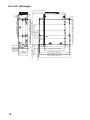
For 5.25" Half Height
79.2 0.3mm [3.12" 0.01"]
79.2 0.3mm [3.12" 0.01"]
47.5 0.3mm
[1.87" 0.01"]
7.0mm
[0.28"]
79.2 0.3mm [3.12" 0.01"]
47.5 0.3mm
[1.87" 0.01"]
94.0 0.5mm [3.70" 0.02"]
21.8 0.5mm
[0.86" 0.02"]
41.2 0.5mm
[1.62" 0.02"]
9.9 0.5mm
[0.39" 0.02"]
139.6 0.5mm [5.50" 0.02"]
146.0 0.5mm [5.75" 0.02"]
149.0 0.5mm [5.87" 0.02"]
155.0 0.5mm [6.10" 0.02"]
70.0 0.3mm [2.76" 0.01"]
42.0 0.3mm
[1.65" 0.01"]
4-M3
6-M3
+
_
+
_
+
_
+
_
+
_
+
_
+
_
+
_
+
_
+
_
+
_
+
_
+
_
+
_
+
_
+
_
+
_
+
_
+
_
+
_
+
_
+
_
+
_
+
_
+
_
+
_
31.0 0.3mm [1.22" 0.01"]
+
_
+
_
+
_
+
_
+
_
+
_
7.6 0.5 mm [0.3" 0.02"]
+
_
+
_
9.8 0.6 mm
[0.39" 0.02"]
+
_
+
_
7.4 0.6mm [0.29" 0.02"]
+
_
+
_

19
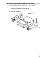
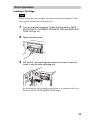
Reconfiguring from 5.25" Model to 3.5" Model
You can reconfigure the 5.25" model to the 3.5" model yourself.
1 Remove the 2 screws for each side rail.
2 Take the side rail off.
Side Rail (L)
Side Rail (R)

20
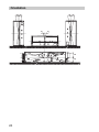
Orientation
10
10
10
10
10 10
10
10
Page is loading ...
Page is loading ...
Page is loading ...
Page is loading ...
Page is loading ...
Page is loading ...
Page is loading ...
Page is loading ...
Page is loading ...
Page is loading ...
Page is loading ...
Page is loading ...
Page is loading ...
Page is loading ...
Page is loading ...
Page is loading ...
Page is loading ...
-
 1
1
-
 2
2
-
 3
3
-
 4
4
-
 5
5
-
 6
6
-
 7
7
-
 8
8
-
 9
9
-
 10
10
-
 11
11
-
 12
12
-
 13
13
-
 14
14
-
 15
15
-
 16
16
-
 17
17
-
 18
18
-
 19
19
-
 20
20
-
 21
21
-
 22
22
-
 23
23
-
 24
24
-
 25
25
-
 26
26
-
 27
27
-
 28
28
-
 29
29
-
 30
30
-
 31
31
-
 32
32
-
 33
33
-
 34
34
-
 35
35
-
 36
36
-
 37
37


Sony AITI390 Owner's manual
- Type
- Owner's manual
- This manual is also suitable for
Ask a question and I''ll find the answer in the document
Finding information in a document is now easier with AI
Related papers
Other documents
-
 ADIC Tool Storage 6-00025-01 User manual
-
Overland Storage PowerLoaders AIT-LP3L219T/RB User & Installation Manual
-
 ADIC Oven 5.4 User manual
-
Compaq AIT 35 LVD Owner's manual
-
TEAC GX-1 User manual
-
Quantum AML/2 User guide
-
 ADIC Scalar AIT 440 Installation guide
-
Topcon AIT-250W User manual
-
RM dualserv pro series User manual
-
Compaq AIT 35 LVD Reference guide


