Polaris Ranger Installation guide

Type
Installation guide

Polaris Ranger, a versatile and powerful side-by-side vehicle, offers exceptional performance for various outdoor activities and tasks. With its robust construction and impressive capabilities, the Polaris Ranger can handle challenging terrains, making it an ideal choice for hunting, farming, construction, and recreational adventures. Its spacious cargo bed allows for easy transportation of gear and equipment, while its comfortable seating and intuitive controls ensure a smooth and enjoyable ride.

Polaris Ranger, a versatile and powerful side-by-side vehicle, offers exceptional performance for various outdoor activities and tasks. With its robust construction and impressive capabilities, the Polaris Ranger can handle challenging terrains, making it an ideal choice for hunting, farming, construction, and recreational adventures. Its spacious cargo bed allows for easy transportation of gear and equipment, while its comfortable seating and intuitive controls ensure a smooth and enjoyable ride.

POLARIS RANGER XP 900/570
Winch Mount
Part #: 
Hardware Kit: 

ITEM # QTY DESCRIPTION
1 (1x) Winch Mount Plate
2 (1x) Replacement Grill Wide
3 (1x) Fairlead Converter Bracket

ITEM # QTY DESCRIPTION
4.1 (3x) 5/16”-18 x 1” Hex Flange Bolt
4.2 (1x) 5/16”-18 Hex Flange Nylock Nut
4.3 (2x) M10x1.50 x 25mm Hex Head Bolt
4.4 (2x) M10 Lock Washer
4.5 (2x) 3/8”-16 x 1.00” Carriage Bolt
4.6 (2x) 3/8”-16 Hex Flange Nylock Nut
4.7 (1x) HK-031 (UTV Mini-Rocker Hardware)
4.8 (1x) 22-18GA Spade Insulated Terminal
4.9 (1x) M10x1.50 x 35mm Hex Head Bolt
4.10 (1x) M10x1.50 Hex Nut
* Note: This is the standard location for contactor with
standard length winch wires; if your wires are too
short, you can drill holes on the opposite side of the
hood compartment and ax contactor as needed. Use
caution when drilling holes, there is a radiator hose
directly under this location.

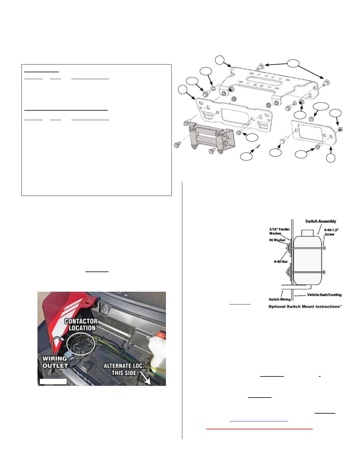
4. For all wide winches with leads on the   
 in a  orientation, you will need to
 the  so they do not interfere with the
bumper frame once re-assembled. If your winch has
leads on the inside (near the spool), then move to
Step 5, otherwise see  and continue.
In general, to rotate the leads, loosen the two screws
on the endcap in , then rotate the entire
motor housing 90 or 45 degrees (depending on your
winch). For detailed instructions go to the Support
section at www.kproducts.com and download
Winch Motor Lead Rotaon Instrucons.
Page 1 of 5Copyright ©2021 - Kappers Fabricating, Inc. E - 3/8/2021
3. Use included Mini- Rocker Switch Hardware Kit (HK-
031) to fasten a handle bar mounted mini-rocker switch
to the dash or any desired location.
a. Remove handlebar mount
hardware from the switch.
b. Locate desired mounting
location.
c. Mark & drill 2 switch holes
through dash using switch
housing as a template.
d. Drill a 3rd hole for switch
wiring.
e. Assemble per .
Figure 2.


1. Begin by turning machine o and disconnect the
battery cables. Locate the battery compartment under
the passenger or rear passenger seat. Lift bench seat
up and pull out storage compartment. First remove
the ground(Black), then positive(Red) terminal.
2. Open the hood and nd the recommended contactor
location shown in . Ax the contactor to the
recommended location with hardware included with
your winch.
*Fairlead and fairlead bolts supplied with winch*
Figure 1
Figure A.
2
3
1
4.1
4.5
4.3
4.4
4.6
4.1
4.2
4.8
4.10
4.9

5. Connect the shortest wires (usually  & )
to the motor end of the winch per the ALTERNATE
WIRING DIAGRAM shown in    .
Connect  wire to NEG(-)  winch post;
connect  wire to POS(+)  winch post.
6. Assemble your winch to the mount plate. Depending
on your winch there are three dierent bolt pattern’s
shown in the following images. Use the hardware
included with your winch. Most winches will be
installed upside down with the clutch end on the
passenger side of the machine and the motor to the
drivers side once bolted to the machine.
Page 2 of 5Copyright ©2021 - Kappers Fabricating, Inc. E - 3/8/2021
Front Lower
View from Side
Figure 3.

7. Remove the front bumper. Remove the 4 bolts
attaching front bumper (B) and (C) as shown in
Figure 4. (See inset) views. Remove OEM plastic
grill from bumper frame held in place by 2 Torx head
screws (D). Discard OEM grill.
WIDE Rollers
Discard Fairlead Converter
Two Hole Winch Install
3.100” Bolt-up Pattern
CABLE
Front
Sandard Winch Install
3.00”X4.875” Bolt-up Pattern
CABLE
WIDE Winch Install
3.00”X6.60” Bolt-up Pattern
CABLE
Figure 5
Figure 4
10. Lift assembled winch and mount into position on
machine frame as shown in Figure 7. Fasten to frame
using two M10 bolts & lock washers at positions (E)
and two 3/8” carriage bolts & ange nuts at positions
(F). Loosely start the top bolts rst to make install
easier. Install carriage bolts (F) with the head to the
rear of the frame and nut on the front side with the
mount plate as shown in Figure 7 and Figure A (pg.1).
Tighten all hardware evenly.
8. Install replacement grill to bumper as shown in
Figure 5&6 using original Torx screws (D). Do not
fully tighten.
Note: If you have a two hole, or a standard winch you will
need the converter bracket. If you have a wide winch
discard the converter bracket, shown in (Figure 6).
Without the bracket Install bolt (Y&X) directly to the
grill & fairlead using hole (Z).
9. Install fairlead to grill & bumper assembly as shown in
Figure 5&6. FOR STANDARD WINCH: At X, Pass
bolt (4.9) through fairlead, converter bracket, grill,
and bumper frame rails, then tighten with nut (4.10).
If using Converter bracket install fairlead bolt supplied
with winch (Y) directly to the converter bracket. Use
Bolt (4.1) and Flange Nylock Nut (4.2) from hardware
kit to fasten grill to bumper frame at location (Z).
Page 3 of 5Copyright ©2021 - Kappers Fabricating, Inc. E - 3/8/2021
11. Re-assemble bumper to frame, using bolts removed
in step 7. Loosely ax nuts to bolts allowing for
nal adjustment of grill to mount plate. Fasten grill
to mount using two 5/16” Flange Bolts included in
hardware kit (See Figure A pg.1). Evenly tighten all
mount and frame hardware.

12. If you have a Crew model, you will need to use the
extended 11’ cables included with the Crew Kit
(KFI#: UTV-WEK Sold Separately)
Locate starter solenoid next to battery as shown
in Figure 8. Using the ALTERNATE WIRING
DIAGRAM (Figure 15, pg.5) as a guide, attach the
 wire to the battery fed solenoid
as shown in Figures 8&9. Then, attach the 
 wire to the ground post as shown in Figure 9.
Figure 9.
D
D
Y
Standard Roller
Needs Fairlead Converter
z
X
Figure 8
Figure 10
F
E
F
E
Figure 7
Figure 6
G
H
J
Page 4 of 5Copyright ©2021 - Kappers Fabricating, Inc. E - 3/8/2021

17. Attach the ignition fed wire (RED) from your switch
to the post labelled (J) in Figure 14, using the 22-
18GA Spade Insulated Terminal included in the
winch mount hardware kit.
18. Connect wire to contactor according to 
 shown in .
19.   ,    
cable, and  and shrouds
removed.
13. Remove plastic shroud covering center oor console
by taking out the the 4 plastic rivets (A) shown in
Figure 10. Route the longest wires (usually 
& ) included with your winch from the
battery to the contactor location by passing through
the opening to the battery compartment and through
the front foot well as shown in Figure 11.
13. Finish routing longest wires up along frame and
through outlet noted in Figures 1 (pg1) and 12. Do
NOT connect wires to contactor at this time.
15. Route wires from winch motor end to the contactor
location () by running them in front of
the radiator. Do NOT connect wires to contactor at
this time.
16. Route switch wiring behind front dash and through
a wiring grommet located behind the glove box. See
grommet (G) located in Figure 13. You may remove
the top access panel (H) to aid in routing and securing
wiring.
H
G
J
Figure 11
Figure 12
Figure 13
Figure 14
Figure 15.
E - 3/8/2021Page 5 of 5Copyright ©2021 - Kappers Fabricating, Inc.
  • Page 1 1
  • Page 2 2
  • Page 3 3
  • Page 4 4
  • Page 5 5

Polaris Ranger Installation guide

Type
Installation guide

Polaris Ranger, a versatile and powerful side-by-side vehicle, offers exceptional performance for various outdoor activities and tasks. With its robust construction and impressive capabilities, the Polaris Ranger can handle challenging terrains, making it an ideal choice for hunting, farming, construction, and recreational adventures. Its spacious cargo bed allows for easy transportation of gear and equipment, while its comfortable seating and intuitive controls ensure a smooth and enjoyable ride.

Ask a question and I''ll find the answer in the document

Finding information in a document is now easier with AI