Trane TRECEIV5AHA0DA Installation guide

Type
Installation guide

Trane TRECEIV5AHA0DA is a wireless control receiver designed for use with U-Match Inverter Systems and MultiSplit Inverter Systems. It allows for remote control of compatible indoor units, providing convenient operation and enhanced comfort. With the ability to receive signals from a wireless remote controller, you can easily adjust settings such as temperature, fan speed, and mode, from anywhere within range. Installation is straightforward, with the receiver featuring an oblong hole and screw installation holes for secure mounting on a wall or ceiling.

Trane TRECEIV5AHA0DA is a wireless control receiver designed for use with U-Match Inverter Systems and MultiSplit Inverter Systems. It allows for remote control of compatible indoor units, providing convenient operation and enhanced comfort. With the ability to receive signals from a wireless remote controller, you can easily adjust settings such as temperature, fan speed, and mode, from anywhere within range. Installation is straightforward, with the receiver featuring an oblong hole and screw installation holes for secure mounting on a wall or ceiling.

Wireless Control Receiver for Concealed Unit
UMatch Inverter Systems
MultiSplit Inverter Systems
Installation and operation manual
SAFETY WARNING
Only qualified personnel should install and service the equipment. The installation, starting up, and servicing of
heating, ventilating, and air-conditioning equipment can be hazardous and requires specific knowledge and training.
Improperly installed, adjusted or altered equipment by an unqualified person could result in death or serious injury.
When working on the equipment, observe all precautions in the literature and on the tags, stickers, and labels that are
attached to the equipment.
April 2021
Confidential and proprietary Trane information
MS-SVX080A-EN
Control system
2
Before Installation and Operation
The packaging contains the following items. Check the contents and the number of pieces.
Name Quantity Comments
Remote receiver 1 With connection cable
Belt 1 To x the cable
Screw 2 To x the receiver to the
wall or ceiling(M4,25mm)
Installation
Step1:
Make sure there are one oblong hole and two screw installation holes on the installation place(ceiling or
wall or winding outlet nearby).
Control system
3
Step2:
Remove the cover by a at-blade screwdriver
Control system
4
Step3:Pass the connecting wiring through the groove and pass it through the hole slit (the groove not
provided)
connecting Wire
Step4:
Fix the receiver to the choosen installation place by 2 M4 screw(provided).
Step5: Install the cover
Control system
5
Wiring method
To nd the remote receiver port on indoor unit PCB(please refer to the indoor unit wiring diagram)
Ports and functions
COMP: Compressor
indicator(light when
compressor running )
Installation hole
Wire: connect the
indoor unit PCB and
receiver
TIMER: timer indicator(light
when set the timer function)
OPER: Power indicator(light
when the indoor unit was set
to on state)Emergency switch:
Press to shut down the units
when the indoor unit was in ON
state (Press to start the units
in auto mode when the indoor
unit was in OFF state(setting
temperature 24)
Signal receive window
Control system
6
Malfunction indication
Indication of indoor unit alarm code.
The indoor unit malfunction can be indicated by the controller’s LED light “OPER”:
LED “OPER” ash times correspond to the indoor unit error code, for example:“OPER” ash 3 times,the
unit error code will be 3.
Flash times stand for indoor
unit error code(the premise is
TIMER is not ashing)
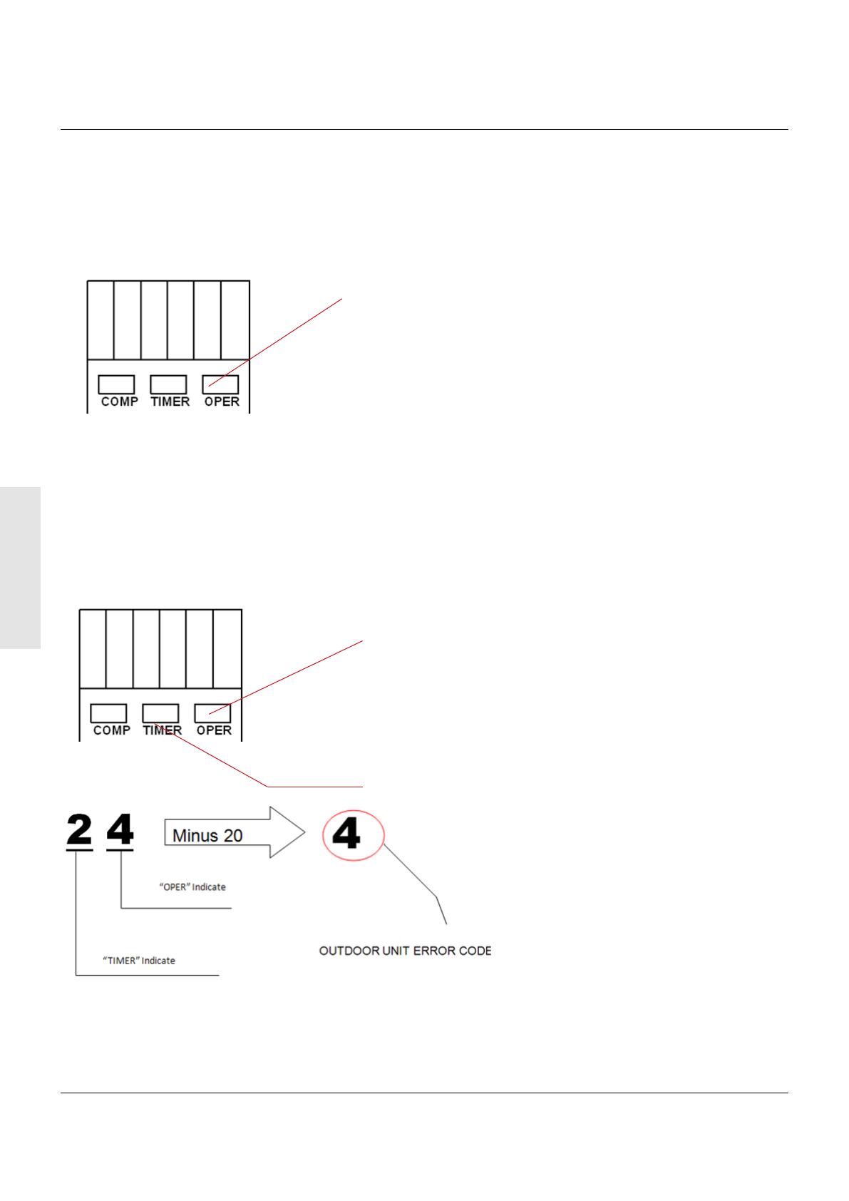
Indication of outdoor unit alarm code.
For the outdoor failure, timer LED and running LED will indicate, the method as follows:
Flash times of the “TIMER” stands for ten's place and ash times of the “OPER” stands for one's place.
“TIMER”will ash rstly,2 seconds later, “OPER”will ash too. After that,4 seconds later, they will ash in
turns again. Flash times equals to the outdoor unit error code plus
20.For example, if the failure code of outdoor is 4,the LED “TIMER”will ashes 2 times, then
“OPER”ashes 4 times.
Flash times stands for one's place
Flash times stands for ten's place
Refer to the maintenance manual or the trouble shooting list to get the information about the error code.
Note:
this malfunction indication is used for R410a super match classic series, Smart power series,
R32 match plus series.
©2020 Trane
Confidential and proprietary Trane information
Trane has a policy of continuous product and product data improvement and reserves the right to change design and specifications without
notice. We are committed to using environmentally conscious print practices.
Trane - by Trane Technologies (NYSE: TT), a global climate innovator - creates comfortable, energy
efficient indoor environments for commercial and residential applications. For more information,
please visit trane.com or tranetechnologies.com.
  • Page 1 1
  • Page 2 2
  • Page 3 3
  • Page 4 4
  • Page 5 5
  • Page 6 6
  • Page 7 7

Trane TRECEIV5AHA0DA Installation guide

Type
Installation guide

Trane TRECEIV5AHA0DA is a wireless control receiver designed for use with U-Match Inverter Systems and MultiSplit Inverter Systems. It allows for remote control of compatible indoor units, providing convenient operation and enhanced comfort. With the ability to receive signals from a wireless remote controller, you can easily adjust settings such as temperature, fan speed, and mode, from anywhere within range. Installation is straightforward, with the receiver featuring an oblong hole and screw installation holes for secure mounting on a wall or ceiling.

Ask a question and I''ll find the answer in the document

Finding information in a document is now easier with AI