Page is loading ...

REVISION A
Form No. 3309583.049 10/16
(French 3309584.047_A)
©2016 Dometic Corporation
LaGrange, IN 46761
INSTALLATION & OPERATION
SUPPLEMENT
USA
SERVICE OFFICE
Dometic Corporation
1120 North Main Street
Elkhart, IN 46514
CANADA
Dometic Corporation
46 Zatonski, Unit 3
Brantford, ON N3T 5LB
CANADA
SERVICE CENTER &
DEALER LOCATIONS
Please Visit:
www.eDometic.com
RECORD THIS UNIT INFORMATION
FOR FUTURE REFERENCE:
Model Number
Serial Number
Date Purchased
This manual must be read and
understood before installation, ad-
justment, service, or maintenance
is performed. Modication of this
product can be extremely hazard-
ous and could result in personal
injury or property damage.
Lire et comprendre ce manuel avant de
procéder à l'installation, à des réglages,
de l'entretien ou des réparations. Toute
modication de cet appareil peut être ex-
trêmement dangereuse et entraîner des
blessures ou dommages matériels.
Important: This Supplement must stay with unit.
Owner read carefully.
Model
954086.000
954091.000
Patent Pending

2
X TEND A-ROOM
TM
INSTALLATION AND OPERATION SUPPLEMENT
SPECIFICATIONS
A
B
C
D
E
SAFETY INSTRUCTIONS
This manual has safety information and instruc-
tions to help users eliminate or reduce the risk
of accidents and injuries.
RECOGNIZE SAFETY INFORMATION
This is the safety-alert symbol. When you see this
symbol in this manual, be alert to the potential
for personal injury.
Follow recommended precautions and safe op-
erating instructions.
UNDERSTAND SIGNAL WORDS
A signal word , WARNING OR CAUTION is used
with the safety-alert symbol. They give the level
of risk for potential injury.
indicates a potentially hazard-
ous situation which, if not avoided, could result
in death or serious injury.
indicates a potentially hazard-
ous situation which, if not avoided, may result in
minor or moderate injury.
used without the safety alert
symbol indicates, a potentially hazardous situa-
tion which, if not avoided, may result in property
damage.
Read and follow all safety information and in-
structions.
Model 954086.000
Min./Max.
954091.000
Min./Max.
A = Length 81-1/2" 88-1/2"
B = Front (Height) 75" 75"
C = Rear (Height) 79-1/2"/86-1/2" 86-1/2"/96-1/2"
D = Expandable
Rear Width
86"/91" 91"/99"
E = Ramp Stand
*Range
16"/28" 16"/28"
Capacity 1,200 lbs. 1,200 lbs.
* Ramp stand adjusts with one inch increments.

3
X TEND A-ROOM
TM
INSTALLATION AND OPERATION SUPPLEMENT
GENERAL INSTRUCTIONS
These instructions must be read and under-
stood before installation of this kit. Modica-
tion of this product can be extremely hazard-
ous and could result in personal injury and/or
property damage.
The X Tend A-Room
TM
is designed to be installed around
the loading ramp opening of a cargo type trailer, allowing
users to enjoy the extra living space.
Product features and specications as described or il-
lustrated are subject to change without notice. Installation
methods not described in this manual must have written
approval from Dometic Corporation.
Important: Read the entire Installation and Operating
Instructions carefully before starting the installation.
Contents:
(1) Instructions (4) Snap Fasteners
(1) Roll of Hook Tape (1) Fabric Assembly.
(1) Oxford Storage Bag (4) Ramp Floor J-Hooks
(1) Ctr Roof Pole Assm. (1) Front Pole Assm.
(2) Ramp Stand (1) Rear Pole Assm.
(1) Pole Storage Bag (4) #8 x 3/4" Screws
(1) Tread Plate Set
Tools Required:
Power Drill/Screwdriver
INSTALLATION
Park the trailer on at and level surface for the initial instal-
lation. This will insure that the X Tend A-Room
TM
will be
straight and square with the trailer.
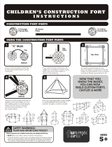
A. Ramp Stand Assembly
1. Find the channel with a threaded nylon insert .
Place the threaded nylon insert with the notch
up.
2. Place the second channel with a hole across the
rst channel with the hole on top forming the letter
"X".
3. The stand pole with the stud bolt is screwed into the
nylon insert through the channel with the hole. This
should be tightened so there is no movement.
4. The top stand pole slides on the bottom assembly
and is locked in place with the ball pin. See Fig.
1.
Note: Each ramp stand has a rubber coating on the top
plate to prevent scratching of the ramp. There is also a
tread plate set included to protect ramp's surface where
ramp rests on ramp stands.
B. Ramp Preparation
1. Place ramp stands at the approximate positions for
each corner of the ramp. If terrain is not level, add
leveling blocks as necessary to even out weight
and level to ramp stands.
2. Pull the ball pin and raise/lower each ramp stand
to the approximate position where the ramp will
be approximately level. Align stand extension with
the closest hole in the base and replace the stand
pin.
3. Lower the ramp and move the ramp stands in posi-
tion under ramp's door frame corners, where ramp
is strongest. Mark this spot. Screw tread plates,
one on each side, onto the ramp where ramp stand
location had been marked. Then place stands under
door frame corners where tread plates are located.
Tread plates are provided to prevent scratching of
ramp surface with ramp stand tops.
4. To reduce the possibility of ramp stands acciden-
tally getting kicked over insert tent stakes through
each of the 2 holes on both ramp stands.
Failure to place stands under ramp's door
frame could cause damage to door's outer
berglass surface when ramp is placed under
load.
FIG. 1
Ball Pin
Channel With
Nylon Insert
Stand Pole
Stud Bolt
Top Stand
Pole
Lower Stand
Pole
Channel With
Hole
C. Description Of Pole Assemblies
There are 3 pole assemblies:
• Center Roof Pole Assembly
• Rear/Frame Pole Assembly
• Front Pole Assembly
Some pole assemblies are shock corded; all are num-
bered with stickers to identify matching assembly poles
and all are painted to make it easier to identify pole
assemblies: Center roof pole assembly is white, front
pole assembly is white, and rear/frame pole assembly
is black. See Figs. 2, 3 & 4.

4
X TEND A-ROOM
TM
INSTALLATION AND OPERATION SUPPLEMENT
b. Front pole assembly
The front pole contains 11 pieces. When as-
sembled, the horizontal poles will form an
arch between the vertical poles. The vertical
poles have a ball which is inserted into an
end ball base and attached to the ramp oor.
See Fig. 3.
Extend the vertical telescoping poles to their
longest length. Lock in place with the lock lever.
See Fig. 3.
c. Rear/Frame Pole Assembly
The rear/frame pole when assembled, will form
a square. The vertical poles will be capped on
the bottom end with rubber caps to prevent
slipping and will be placed on the trailer oor.
See Fig. 4.
D. X Tend A-Room
TM
Assembly
1. Spread the X Tend A-Room
TM
fabric on the cargo
ramp. The zippers should be on the inside and
the open end of the room towards the trailer
opening.
2. Locate the fabric sleeves on each side of the
open end on the rear of fabric assembly. Assem-
ble the vertical side poles 1C, 1D and 1E of the
rear pole assembly. Place the lock levers in the
down/locked position. Feed the vertical side pole
caps down through the two side panel sleeves,
starting at the top panel.
3. Assemble the horizontal poles (1A & 1B) of the
rear pole assembly. Place the lock levers in
the down position and slide them through the 4
sleeves across the roof panel of the fabric. See
Fig. 4.
4. Insert the horizontal pole assembly into the verti-
cal side poles to form the rear frame.
5. The fabric and rear pole assembly are moved in-
side the trailer door opening. Extend the horizon-
tal frame of the rear pole assembly equally until
they touch the trailer side walls. Place the levers
in the locked position.
Note: The width of the room can be increased by unzip-
ping the dart (extra fabric) in the center of the roof fabric.
6. Raise each vertical side pole until the horizontal
pole touches the trailer ceiling. Place the levers in
the locked position.
7. The rear pole assembly will hold the X Tend A-
Room
TM
in place inside the trailer.
1. Extend all 3 pole assemblies to their longest
length.
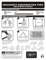
a. Center Pole Assembly
The center pole assembly is made of 3 piec-
es and rest along the expansion zipper on the
center of the roof of the inside of the X Tend
A-Room TM and parallel with the zipper. The
pole has a "C" clip on one end and a J-sup-
port on opposite end. See Fig. 2.
FIG. 2
3A
3B
"C" Clip
Ball End
w/J-Support
Lock
Lever
3C
Center Pole Assembly
FIG. 3
2A
2B
2C
2D
2E
2F
Ball Ends
w/Bases
Front Pole Assembly
Lock
Levers
FIG. 4
1A
1B
1C
1D
1E
Rear/Frame Pole Assembly
Caps
Caps

5
X TEND A-ROOM
TM
INSTALLATION AND OPERATION SUPPLEMENT
8. Assemble the front pole assembly inside the X
Tend A-Room
TM
.
9. Grasp the center of the front pole assembly arch,
place it against the roof fabric; and walk towards
the end of the ramp. Place the arch at the front
top stitch line. Wrap the 5 hook/loop belts around
the arch poles to hold place.
10. Keep ball ends of side poles at ramp opening/
hinge and extend the side poles as much as pos-
sible without lifting the X Tend A-Room
TM
off the
ramp. The side poles should be at an angle.
11. Clip the center pole J-support in the center of the
horizontal frame on the rear frame pole assem-
bly. The ball socket must be facing toward room.
See Fig. 5.
12. Assemble the center rafter roof pole and place
the ball end into the socket on the Center pole
support. See Fig. 5.
FIG. 5
Clip The Center
Pole J-Sup-
port In Center
Of Horizontal
Frame Of Rear
Pole
Face Ball Socket
Toward Room
Fabric
13. Unlock the lever and pull the center rafter pole
until C-Clip can be snapped onto the center of the
arch of the front pole assembly. Stretch the roof
fabric taut and lock lever.
Note: The center rafter pole will pop out of the ball socket
if too much tension is added.
14. A fabric ap 3" wide with loop tape sewn in, sur-
rounds the door opening of the X-Tend A-Room-
TM
. The hook tape must be placed where it will
stretch the fabric and seal around the door frame.
Place this fabric ap against the walls and ceil-
ing and mark the location. Peel the backing off
the hook tape (approximately 12" at a time), and
press it in place on the walls and ceiling.
Note: To ensure adhesion of the tape to the walls and ceil-
ing, the surfaces must be clean and dry.
15. Locate a place for the ball end bases on the ramp
surface, where they will be out of the way; but al-
low the ramp to close. The "OPEN" cutout should
face the direction of the ramp end to allow for the
pole rotation to different angles.
16. Attach the two ball end bases, one on each side
of the ramp with 2 #8 x 3/4" screws. Snap the front
pole assembly ball ends into the bases. Loosen
the lock and extend each side equally until the
fabric is taut.
17. The fabric is held against the ramp with an elastic
cord stretched in a sleeve sewn into the bottom
hem of the fabric assembly. At the ends of the
elastic cord is a rubber coated hook that is to be
attached to the ramp.
If the elastic cord hook is not large enough to t
on the edge of the ramp, four large rubber coat-
ed J-hooks are provided. Place the J-hook on the
ramp edge and the elastic cord hook is secured
in the J-hook.
18. Pull the front bottom corners taut and mark the lo-
cation where the eyelet grommet makes contact
to the ramp. This is repeated for both sides. Drill
1/8" pilot hole (9/64" in metal) and install a snap
fastener on each side.
19. The corners of the roof fabric has web belts with
buckles. Fasten the web belt to the corners of the
rear/frame pole assembly and stretch the fabric
tight to reduce water pooling.
20. Water Bags/Weights 3105851.004 (available at
your Dometic Dealer) can be added along the
bottom for added bug protection.
E. Operating Tips
1. Privacy panels can be unzipped and rolled up to
allow air circulation.
2. The front panel can be unzipped and rolled up;
however, this will open the end of the room and
the possible danger of someone stepping off the
ramp.
3. Storage pockets are located on both sides of the
X Tend A-Room
TM
for personal items.
Important: If trailer is equipped with a bed, DO NOT
ROLL BED DOWN if room poles are in place.

6
X TEND A-ROOM
TM
INSTALLATION AND OPERATION SUPPLEMENT
7. Roll the fabric assembly tightly around the poles
in the pole storage bag squeezing out the air. In-
sert the fabric and poles into the X Tend A-Room-
TM
storage bag. Store in a dry place.
8. Disassemble ramp stands in reverse of assembly
(see section "A" on page 3), and place in the stor-
age bag.
6. The room is folded by bringing the sides into the
middle. Fold the each side again to the middle
until the fabric is the width of the pole storage
bag.
TO REDUCE THE RISK OF DEATH, PERSONAL INJURY, FIRE OR DAMAGE:
1. The stands support the X Tend A-Room
TM
and ramp. The stands are designed to support
a total of 1,200 pounds including persons, equipment and ramp.
2. Do not use grills, hibachis, camp stove or gas burning lamps inside the X Tend A-Room-
TM
.
3. Never operate generators, motorcycles, any internal combustion engines inside the X Tend
A-Room
TM
.
4. Close attention is necessary when used by or near children. Do not allow children or adults
to lean against the sides or front of the X Tend A-Room
TM
.
5. Do not suspend electrical lights from rafter poles or allow them to come in contact with
the X Tend A-Room
TM
fabric.
6. Do not modify or change the installation of this X Tend A-Room
TM
.
7. Follow all trailer manufacturers instructions regarding ramp use and limitations.
8. Use only as described in this manual.
Personal injury may result from falling or
stepping off the end of the cargo ramp when
the room is installed.
F. Room Storage
Note: If room is put away when conditions are wet, it
should be set up and allowed to dry as soon as possible
to prevent mold and mildew.
1. Loosen and unfasten buckle straps at rear top
corners of the X Tend A-Room
TM
.
2. Unfasten hooks on the elastic cord and snap fas-
teners at bottom of room front corners.
3. Remove center roof pole assembly by un-clip-
ping the C-clip from arched front pole assembly.
Remove the Center pole support with ball socket
from rear/frame pole assembly. Disassemble
center pole and place in pole storage bag.
4. Carefully pull the ball ends out of the ball end
bases. Loosen the lock levers and shorten the
side poles to the shortest length and lock the
levers. The front fabric will start to collapse. Re-
move the ve hook/loop straps from the arch and
the pole assembly is free and the fabric will fall
to the ramp. Disassemble front pole and place in
pole storage bag.
5. Loosen the lock levers and lower the rear/frame
pole assembly to its shortest height. Place levers
in the lock position. The entire X Tend A-Room
TM
will be completely on the ramp. Loosen the locks
on the horizontal pole and collapse to the short-
est length. Remove vertical side pole from the
horizontal pole and slide it out of the sleeves on
the fabric. Repeat for other side. Do the same
with the horizontal pole and take apart the entire
rear/frame pole to be placed into the pole storage
bag. Tie the pole storage bag closed.

7
X TEND A-ROOM
TM
INSTALLATION AND OPERATION SUPPLEMENT
THE SELLER NAMED BELOW MAKES THE FOLLOWING WARRANTY WITH
RESPECT TO THE DOMETIC PRODUCT:
1. This Warranty is made only to the rst purchaser (hereinafter referred to as the “Original Purchaser”) who acquires the product for his own use
and is installed and operated within the continental United States and Canada.
2. This Warranty will be in effect for one (1) year from the date of purchase by the original purchaser. It is suggested that the original purchaser
retain a copy of the dated bill of sale as evidence of the date of purchase.
3. This Warranty covers only specied parts which shall be free from defects in material and workmanship under normal use. This warranty does
NOT cover conditions unrelated to the material and workmanship of the product. Such unrelated conditions include, but are not limited to: (a)
damage not reported within seven (7) days of ownership; (b) failure or damage caused by storms, rain, water pooling, or any acts of God; (c)
faulty installation and any damage resulting from such; (d) the need for normal maintenance and any damage resulting from the failure to
provide such maintenance; (e) failure to follow Sellers instructions for use of this product; (f) any accident to or misuse of any part of this product
and any alteration by anyone other than the Seller or its authorized representative; (g) damage or failure caused by installation of accessories
not manufactured and marketed by the Seller; and (h) normal wear and product abuse.
4. The specied parts covered by this warranty, where applicable, are as follows: (a) Roller tube against rust, corrosion and extrusion defects; (b)
Fabric free from quality defects (normal wear is not covered); (c) Screen assemblies free from quality defects (normal wear is not covered); (d)
Torsion assemblies, including motor-driven assemblies, against extrusion defects, electrical faults, or breakage; and (d) Hardware against extru-
sion defects.
5. In order to obtain the benets of this warranty, you should return the product which you nd defective to the Seller named below or to a Dometic
Authorized Service Center during the period that this warranty is in effect. The original owner is responsible for all charges incurred in delivery
of the product to the Seller, or Dometic Authorized Service Center, and in pick up after the warranty service has been completed. To obtain the
location of the nearest Authorized Service Center, please call 1-800-544-4881. In Canada, call 1-519-720-9578.
6. Any item returned in the manner described in paragraph 5 will be examined by the Seller or the Authorized Dometic Service Center. If it is found
that the returned item was defective in material and workmanship, the Seller or the Authorized Dometic Service Center will repair the product
per the terms of this one (1) year limited warranty without charge for material or labor during the rst year of ownership by the original purchaser.
CONFIRM THE SERVICE AGENCY IS AN AUTHORIZED DOMETIC SERVICE CENTER. DO NOT PAY THE SERVICE AGENCY FOR WAR-
RANTY REPAIRS. SUCH PAYMENTS WILL NOT BE REIMBURSED.
7. Dometic Corporation will pay freight on replacement parts during the rst ninety (90) days of ownership by the original purchaser.
8. The Seller does not authorize any person or company to create any warranty obligations or liability on their behalf. This warranty is not extended
by the length of time which you are deprived of the use of the product. Repairs and replacement parts provided under the terms of this warranty
shall carry only the non-expired portion of this warranty.
9. In no event shall either Seller be liable for incidental or consequential damages. This includes any damage to another product or products result-
ing from such a defect. Some states do not allow the exclusion or limitation of incidental or consequential damages, so the above limitations may
not apply.
10. Any implied warranty, including the implied warranty of merchantability and tness for any purpose, is limited to the duration of this limited war-
ranty. Some states do not allow limitations on how long an implied warranty can last, so the above limitation may not apply.
11. THIS WARRANTY GIVES YOU SPECIFIC LEGAL RIGHTS, YOU MAY ALSO HAVE OTHER RIGHTS WHICH VARY FROM STATE TO STATE.
No action to enforce this warranty shall be commenced later than ninety (90) days after the expiration of the warranty period. Claims must be
submitted in writing to the Dometic Warranty Department for arbitration.
12 All products (except those specically built for commercial use) are warranted only when installed on vehicles built to R.V.I.A. and C.R.V.A., Z-240
Standards.
13. The Seller reserves the right to change the design of any product without notice and with no obligation to make corresponding changes in products
previously manufactured.
DOMETIC CORPORATION
Warranty Department
1120 North Main Street
Elkhart, Indiana 46514
LIMITED ONE (1) YEAR WARRANTY
/