Page is loading ...

OPERATING INSTRUCTIONS
Proler™ 2
SHORT RANGE DISTANCE SENSOR

2 © SICK AG • Subject to change without notice. • 8017035/ZMO9/2017-06-08
Copyright protection!
This work is copyright-protected. The rights founded by
this shall remain with company SICK AG. Reproduction
of the work or parts of this work shall only be permissible
within the limits of the legal provisions of copyright law.
Changes and abbreviations of this work are prohibited
without the express written agreement of SICK AG.

8017035/ZMO9/2017-06-08 • © SICK AG • Subject to change without notice. 3
Table of contents
1 Introduction ........................................................................................ 8
1.1 Warranty .....................................................................................8
2 Safety Precautions............................................................................. 9
2.1 Safety Precaution Symbols .......................................................9
2.2 Mandatory Precautions .............................................................9
2.3 Precautions for Laser Use ...................................................... 10
2.3.1 Installation Precautions.......................................... 10
2.4 Warning Labels ....................................................................... 11
3 Information Before Use ................................................................... 12
3.1 General Description ................................................................ 12
3.2 Package Contents ................................................................... 13
3.2.1 Included Items ........................................................ 13
3.2.2 Options .................................................................... 13
3.3 Names and Functions of Parts .............................................. 14
3.3.1 Sensor ..................................................................... 14
3.3.2 Laser Emission and Measurement Ranges .......... 15
3.3.3 Cable Wire Colors and Roles .................................. 16
3.4 Installation .............................................................................. 17
3.4.1 Notes for installation .............................................. 17
3.4.2 Installing the Sensor ............................................... 17
4 Setup and Measurement Procedures ............................................. 18
4.1 Before Using the Proler 2 ..................................................... 18
4.1.1 Procedure for Using the Sensor ............................. 18
4.1.2 Setup and Measurement Process ......................... 19
4.2 Quick Setup ............................................................................. 20
4.2.1 Basic Measurement Settings ................................. 20
4.2.2 Return to Main Menu/Measurement Screen ........ 21
4.2.3 Initialize Settings ..................................................... 22
5 Operating the Sensor ....................................................................... 23
5.1 Sensor Screen ......................................................................... 23
5.1.1 Details of the Screen .............................................. 23
5.1.2 Screen Types and Switching Between Screens .... 24
5.1.3 Key Lock Function ................................................... 25
5.2 Main Screen ............................................................................ 25

4 © SICK AG • Subject to change without notice. • 8017035/ZMO9/2017-06-08
5.2.1 Main ......................................................................... 25
5.2.2 Input/Trigger ........................................................... 26
5.2.3 Storage .................................................................... 27
5.2.4 Other ........................................................................ 30
5.3 Setting ..................................................................................... 32
5.3.1 Camera .................................................................... 32
5.3.2 Prole ....................................................................... 35
5.3.3 Area .......................................................................... 38
5.4 Graph/Calc .............................................................................. 40
5.4.1 Graph Items (Area 1 to area 4) .............................. 41
5.4.2 Calc Items (Calculation 1 and calculation 2) ........ 42
5.5 Output ...................................................................................... 43
5.5.1 Output Items (OUT1 to OUT3) ................................ 44
5.5.2 Output Items (OUTA) ............................................... 45
6 PRO2-Navigator Setup Software ..................................................... 47
6.1 Setup Software Requirements ............................................... 47
6.1.1 Operating Environment ........................................... 47
6.2 Software Setup ....................................................................... 48
6.2.1 Installing the Driver ................................................. 48
6.2.2 Install the Software................................................. 49
6.2.3 Settings for High-speed Communication .............. 50
6.3 PRO2-Navigator Screen and Operating ................................. 51
6.3.1 Start PRO2-Navigator .............................................. 51
6.3.2 Main Screen (Measurement Screen) .................... 51
6.3.3 Common Setup ....................................................... 53
6.3.4 How to Change Settings ......................................... 54
6.4 Setup Procedure ..................................................................... 55
6.4.1 Connecting to the Sensor Head ............................. 55
6.4.2 Input/Trigger Settings ............................................. 56
6.4.3 Camera Settings ..................................................... 57
6.4.4 Prole Settings ........................................................ 59
6.4.5 Area Settings ........................................................... 61
6.4.6 Calculation Settings ................................................ 63
6.4.7 Output Settings ....................................................... 64
6.5 Storage Function ..................................................................... 65

8017035/ZMO9/2017-06-08 • © SICK AG • Subject to change without notice. 5
6.5.1 Storage Settings ...................................................... 65
6.5.2 Data storage ............................................................ 66
6.5.3 Prole storage ......................................................... 67
7 Functions .......................................................................................... 69
7.1 Settings Lists and Factory Settings ....................................... 69
7.2 Input/Trigger Settings ............................................................. 74
7.2.1 IN1/IN2/IN3/IN4 .................................................... 74
7.2.2 Reset/Inner hold/Inner trig .................................... 74
7.2.3 Input polar, Inp lter ................................................ 75
7.2.4 Trig action ................................................................ 75
7.2.5 Oset target ............................................................ 75
7.3 Storage Settings ..................................................................... 76
7.3.1 Storage .................................................................... 76
7.3.2 Start cond ................................................................ 76
7.3.3 Intermittent ............................................................. 77
7.3.4 Repeat ..................................................................... 77
7.4 Camera Settings ..................................................................... 78
7.4.1 Camera Mode ......................................................... 78
Operation of the camera mode ................................................................ 80
Mandatory settings when using HDR ..................................................... 82
7.4.2 Image Brightness (Shutter Time and Gain) ........... 83
7.4.3 Camera Range ........................................................ 84
7.4.4 Received Light Waveform and Measurements ..... 85
7.5 Prole Settings ........................................................................ 86
7.5.1 Prole Extraction Settings ...................................... 86
7.5.2 Save Master ............................................................ 89
7.5.3 Prole Correction .................................................... 90
7.6 Area Settings ........................................................................... 95
7.6.1 Measurement Areas ............................................... 95
7.6.2 Measurement functions ......................................... 96
7.7 Calculation Settings .............................................................. 100
7.7.1 Average .................................................................. 100
7.7.2 Hold........................................................................ 100
7.7.3 Span....................................................................... 101
7.7.4 Calculation Formulas ............................................ 101

6 © SICK AG • Subject to change without notice. • 8017035/ZMO9/2017-06-08
7.8 Output Settings ..................................................................... 102
7.8.1 Out target .............................................................. 102
7.8.2 Thresholds and Output ......................................... 102
7.8.3 Out action .............................................................. 104
7.8.4 Oset/Oset Value ............................................... 105
7.8.5 Analog Output Range ............................................ 107
7.9 Common Settings ................................................................. 108
7.9.1 Banks ..................................................................... 108
7.9.2 Baud rate ............................................................... 108
7.9.3 Axis dir ................................................................... 109
7.9.4 On Timing .............................................................. 109
7.9.5 Lang/言語 .............................. 109
7.9.6 Screen Saver ......................................................... 110
7.9.7 Brightness ............................................................. 110
7.9.8 Initialize ................................................................. 110
7.9.9 Version ................................................................... 110
8 Serial Communication ...................................................................111
8.1 Communication Specications ............................................ 111
8.1.1 Communication Specications ............................ 111
8.1.2 Timing Chart During Communication .................. 111
8.1.3 Command Format ................................................. 112
8.2 How to Acquire Measured Values ........................................ 113
8.2.1 Commands for Acquiring Measured Values ........ 113
8.2.2 Communication Command Examples ................. 113
8.3 How to Acquire Proles ......................................................... 114
8.3.1 Commands for Acquiring Prole Data ................. 114
8.3.2 How to Acquire Prole Data .................................. 114
8.4 Storage Data Acquisition Method ........................................ 116
8.4.1 Commands for Acquiring Storage Data ............... 116
8.4.2 How to Acquire Storage Data ............................... 117
8.5 Setting Acquisition and Change Commands ...................... 119
8.5.1 Communication Command Examples ................. 119
8.5.2 Writing Settings to EEPROM ................................. 120
8.5.3 Camera Settings ................................................... 120
8.5.4 Prole Settings ...................................................... 122

8017035/ZMO9/2017-06-08 • © SICK AG • Subject to change without notice. 7
8.5.5 Area Settings ......................................................... 123
8.5.6 Calculation Settings .............................................. 125
8.5.7 Output Settings ..................................................... 127
8.5.8 Input Settings ........................................................ 130
8.5.9 Storage Settings .................................................... 131
8.5.10 Other Settings ....................................................... 133
9 Specications.................................................................................134
9.1 Specications ........................................................................ 134
9.2 Connection diagram ............................................................. 135
9.2.1 Input Circuit Diagram ............................................ 135
9.3 Dimensions ........................................................................... 136
9.4 Timing Charts ........................................................................ 137
9.4.1 Measurement ........................................................ 137
9.4.2 I/O .......................................................................... 139

Introduction
8 © SICK AG • Subject to change without notice. • 8017035/ZMO9/2017-06-08
1 Introduction
Before using this product, conrm that the product you have received is the
product that you requested.
• Read this manual thoroughly, and then keep this manual at hand so that
it can be used whenever necessary.
• If you lose this manual or if you have any questions regarding the
contents contained herein, contact our distributor from whom you pur-
chased the product or download PDF from www.sick.com.
• Trademarks and registered trademarks appearing in this manual are the
property of their respective owners.
• The copyright of this manual is owned by SICK AG. All the contents
contained herein are protected by copyright law. Unauthorized copying of
this manual is strictly prohibited.
1.1 Warranty
SICK AG products have undergone strict inspections. However, should your
product malfunction, conrm the symptoms of the malfunction, and then
contact our distributor from whom you purchased the product.
• The warranty period of this product is 1 year from the time of purchase.
• If a malfunction occurs attributable to the manufacturer, the product will
be replaced free of charge (a replacement will be sent).
However, the following cases are not covered by the warranty.
1. Malfunction caused by improper handling or usage.
2. Malfunction caused by something other than this product.
3. Malfunction caused by unapproved modications or repairs.
4. Malfunction caused by a natural disaster.
The warranty described here is limited to the delivered product.
SICK AG accepts no responsibility for any subsequent damages caused
by a product malfunction.

8017035/ZMO9/2017-06-08 • © SICK AG • Subject to change without notice. 9
Safety Precautions
2 Safety Precautions
Read this manual carefully to ensure safe and correct use of this product.
This manual contains safety precautions that are designed to protect your
health and property as well as the health and property of any other users
of this product. Follow the installation and operating procedures described
in this manual, and do not use this product in any manner not described
herein.
2.1 Safety Precaution Symbols
WARNING
Indicates that incorrect use may lead to a hazardous
situation resulting in injury or death.
CAUTION
Indicates that incorrect use may lead to a hazardous
situation resulting in injury or property damage.
2.2 Mandatory Precautions
WARNING
• Do not look directly at the laser beam or intentionally
shine the laser beam in another person’s eyes. Doing
so may cause eye damage.
• This product cannot be used as protective equipment
for the purpose of protecting the human body.
• Disassembling or modifying this product may cause
injury, re, or electric shock.
• If you detect smoke or a strange odor during operation,
stop operating the product, and then stop the power
supply. If repairs are necessary, inform the distributor
that you purchased the product from.
• Use the product with the voltage indicated in the
specications.
• Do not touch the product or its cable with wet hands.
Doing so may lead to electric shock.
• Do not perform wiring while the power supply is on.

Safety Precautions
10 © SICK AG • Subject to change without notice. • 8017035/ZMO9/2017-06-08
2.3 Precautions for Laser Use
WARNING!
• This product emits a Class 2 (II) visible laser beam that
is compliant with JIS/IEC/FDA laser safety standards.
• A Class 2 (II) warning and explanation label is axed
to the sides of this product.
• If you install this product in a piece of machinery that
will then be exported to the United States, you rst
need the approval of the American Food and Drug
Administration (FDA).
• If you install this product in your own equipment, clearly
indicate to the end user that this is a laser product and
provide explanations that ensure correct handling of
the product.
2.3.1 Installation Precautions
WARNING!
• Installing this product in a location with any of the
following conditions may lead to re, electric shock,
or malfunction:
• High humidity
• High temperatures caused by direct sunlight, etc.
• Very dusty
• Poor ventilation
• High static electricity
• Corrosive or ammable gas is present
• Product is exposed to liquids such as water, oil,
and chemicals
• Product is directly subjected to vibration or shock
• Leave the power supply o during wiring.
CAUTION
• Avoid wiring in parallel with or in the same piping
as high-voltage wires or power lines.
Doing so may lead to malfunctions caused by noise.
Also, shorten the power supply and signal wires as
much as possible.
• Be careful to avoid damaging the cables by pulling
on or applying unnecessary force on them.

8017035/ZMO9/2017-06-08 • © SICK AG • Subject to change without notice. 11
Safety Precautions
2.4 Warning Labels
This section explains the contents and axing position of the warning label
used on this product.
A laser beam is used in the location where this warning label is axed.
Looking directly at the laser beam may lead to loss of eyesight. Be sure
to follow the precautions shown below.
1. Do not look at the laser beam.
2. Do not remove the protective cover.
3. All individuals other than the proper operator must not
approach the product.
EN/IEC 60825-1:2014
Laser radiation – Do not look into the
laser beam – Laser class 2 (EN/IEC
60825-1:2014)
Complies with 21CFR1040.10 and
1040.11 except for deviations pursu-
ant to laser notice No. 50, date June
24, 2007
Identical laser class for issue EN/IEC
60825-1:2007
(IEC 60825-1:2014)
(IEC 60825-1:2014)

Information Before Use
12 © SICK AG • Subject to change without notice. • 8017035/ZMO9/2017-06-08
3 Information Before Use
3.1 General Description
The Proler 2 is a high-precision prole measurement sensor.
The characteristics of this product are shown below.
• This product achieves high-precision measurement by emitting a band-
shaped laser beam and using a light-plane-intersecting method that
triangulates the reected light.
• Settings can be congured, measurements can be performed,
and output can be generated from the sensor. No amplier unit
or other auxiliary devices are necessary.
• Various settings can be set from the sensor or from the dedicated setup
software (PRO2-navigator).
• It is possible to measure 4 areas with a single measurement. For each
area, there are 13 types of measurement functions to select from.
• There are 4 camera modes available. This enables you to select
the optimum settings to match the environment of the production line
to be measured and the state of the target object.
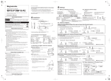
With the light-plane-intersecting method, the reected light from the
emitted band-shaped laser beam is received by the light receiving element
(CMOS), and the prole is then measured from the resulting image data.
With the light-plane-intersecting method, two processes are used to
determine the height and position.
• Triangulation: To determine the height, this process obtains the received
light waveform (the waveform of the reected light) for each vertical line
of the image.
• Projection transformation: To determine the horizontal position,
this process mathematically calculates the actual position from
the image data.
Projection
transformation
Light recieving element (CMOS)
Prole (distance data)
Recieved light waveform
Image (image data)
Figure: Schematic diagram of Proler 2 series measurement

8017035/ZMO9/2017-06-08 • © SICK AG • Subject to change without notice. 13
Information Before Use
3.2 Package Contents
3.2.1 Included Items
Before using this product, conrm that the following items are contained
in the package:
• Sensor
• Mounting screws, M4 × 50 mm (2 pieces)
• Quickstart
• Setup software PRO2-navigator and User manual (USB ash drive)
• Laser warning labels (2 pieces)
3.2.2 Options
Prepare the following options as necessary.
Main cable Communication cable
(USB)
Communication cable
(discrete wire)
6053017,
STL-0H12-G02M (2 m)
6053018,
STL-0H12-G05M (5 m)
6053019,
STL-0H12-G10M (10 m)
6053020,
DSL-DH06-G1M8 (1.8 m)
6053021,
DOL-SH06-G02M (2 m)
6053196,
DOL-SH06-G05M (5 m)
6053197,
DOL-SH06-G10M (10 m)

Information Before Use
14 © SICK AG • Subject to change without notice. • 8017035/ZMO9/2017-06-08
3.3 Names and Functions of Parts
3.3.1 Sensor
1
2
3
4
5
6
7
8
9
ß
à
Number Name Function
1
LCD display This part displays measured results and setting screens.
2
Mounting holes Screws are inserted into these holes to x the sensor in place.
(Diameter: 4.2 mm)
3
Connector for
communi cation cable
Insert a communication cable into this connector to connect the PC and
the sensor.
4
Female connector, HRS, 12-
pin cable
Insert the main cable for power, I/O, and analog output into this connector.
5
Sender area, z-axis The laser beam is emitted from this window.
6
Field of view, x-axis The reected laser light is enters this window.
7
LED Indicator for power on
(green)
This indicator lights when the power is on.
8
LED Indicator for Laser on
(green)
This indicator lights during laser emission.
9
Cursor keys Use these keys to select setting items.
ß
EXIT button Press this button to cancel setting details. Hold down this button (> 1 s) to switch
to the main menu.
à
SET button Press this button to conrm setting details.

8017035/ZMO9/2017-06-08 • © SICK AG • Subject to change without notice. 15
Information Before Use
WARNING
When using the sensor, never look into the laser
exposure window 5. Looking directly at the laser beam
may lead to loss of eyesight.
WARNING
Put the rubber cap on the connector which is not used to
protect from dust and water.
Note!
When using the sensor, do not cover the Sender area 5
or the Field of view 6.
3.3.2 Laser Emission and Measurement Ranges
The sending and receiving area of this product are shown below.
75
(2.95)
0
100
(3.94)
125
(4.92)
Measuring distance
in mm (inch
)
Approx. 32
(1.26)
Measuring widt
h
in mm (inch)
Sending area Receiving area
Measuring width
in mm (inch)
75
(2.95)
0
100
(3.94)
125
(4.92)
Measuring distance
in mm (inch
)
17 (0.67)
22 (0.87)
27 (1.06)

Information Before Use
16 © SICK AG • Subject to change without notice. • 8017035/ZMO9/2017-06-08
3.3.3 Cable Wire Colors and Roles
This section explains the colors of the wires and the roles of the Proler 2
cables.
Main cable This cable is used to supply power to the Proler 2 and for I/O connections.
Color Input or output Description
Purple Input Bank 1/reset
Orange Input Bank 2/hold
Gray
(narrow)
Input Bank 3/trigger
White Input Oset/stop laser emission
Gray
(coaxial core)
Output Analog output (4 to 20 mA)
Gray
(coaxial shield)
— Analog GND
Green — Ground GND
Yellow Output OUT1
Black Output OUT2
Red Output OUT3
Blue — Power supply GND
Brown — 12 to 24 V input
RS-485 cable This cable is used for RS-485 communication between the Proler 2
and a PLC or similar device.
Color Input or output Description
Orange — +A
Yellow — -A
Black — GND
Red — (N.C.)
Brown — (N.C.)
Green — (N.C.)
Reference: For the I/O circuit diagram, see “9.2 Connection diagram.”

8017035/ZMO9/2017-06-08 • © SICK AG • Subject to change without notice. 17
Information Before Use
3.4 Installation
3.4.1 Notes for installation
When you install this product, ensure that there is sucient space around
the product in order to prevent overheating.
Space between sensors
40 mm or more
Space required
above the sensor
40 mm or more
Laser exposure
direction
Laser exposure
direction
The Proler 2 performs measure-
ments by emitting a parallel laser
beam and receiving the reected
light.
During measurement, ensure that
the laser beam and reected light
is not blocked by the target object.
迷光
Stray light
Before using the product, check
that stray light, which is reected
by a wall or by highly reective
objects, does not have an eect
on the measurements.
3.4.2 Installing the Sensor
1. Insert the included mounting screws (two M4 × 50 mm screws)
into the mounting holes to temporarily ax the sensor to a location
that is roughly in the desired location.
2. Measure the distance between the sensor and the detection
target object. Please make sure the measuring object is within the
measuring area.
3. Adjust the sensor position on the basis of the measurement result,
and then use the included nuts and washers to x the screws in place.

Setup and Measurement Procedures
18 © SICK AG • Subject to change without notice. • 8017035/ZMO9/2017-06-08
4 Setup and Measurement Procedures
4.1 BeforeUsingtheProler2
4.1.1 Procedure for Using the Sensor
Before you use the Proler 2, install and setup the sensor according
to the procedure shown below.
1. Installation and light
axis adjustment
Install the sensor such that you can perform accurate measurements
of the measurement target.
Reference: For details on the installation of the sensor, see “3.4 Installation.”
2. Wiring Connect the cables.
3. Settings Congure the settings related to measurement. You can use one of the
following methods to congure the settings.
1. Sensor
• Congure all the settings from the Proler 2.
2. PRO2-Navigator
• Use the dedicated PRO2-Navigator setup software to intuitively
view and change all the settings.
3. Serial communication
• Use RS-485 communication to view and change all the settings
of the Proler 2.
4. Measurement Perform measurements.
With the Proler 2, measurement results can be output using one of the
following methods.
1. Judgment output (control output)
• The Proler 2 is equipped with three judgment outputs (control outputs).
2. Analog current output (4 to 20 mA)
3. Serial communication (RS-485 communication)
4. PRO2-Navigator (monitor display of measured values)
Tips: • Serial communication or PRO2-Navigator is required to output and check
stored data.

8017035/ZMO9/2017-06-08 • © SICK AG • Subject to change without notice. 19
Setup and Measurement Procedures
4.1.2 Setup and Measurement Process
The Proler 2 performs measurements according to the following ow.
Settings are also performed for each of these items.
Laser control input
Trigger signal
Output is
stopped
during
settings.
Camera imaging
Camera settings
Profile
Profile settings
Area measurement
Area settings
Area calculation
Calculation settings
Result judgment and output
Output settings
Out 1
Out 2
Out 3
Analog
Judgment output (control output)
Analog output
1. Trigger
• Images are captured when the set conditions are met.
2. Camera
• An image is captured based to the settings.
3. Prole acquisition
• The prole (the sectional prole made by the reected laser light)
is acquired from the image.
4. Area measurement
• The specied position within the prole is measured.
5. Area calculation
• If necessary, the measured result of the area is calculated. e. g. Area
1 – Area 2 = Calc 1)
6. Result judgment and output
• The measured result is compared against the threshold, and then the
judgment result is output.
Tips: • With the Proler 2, you can save settings related to measurements
in “banks.” Up to eight banks can be saved.
Reference: For details on banks, see “7.9.1 Banks.”

Setup and Measurement Procedures
20 © SICK AG • Subject to change without notice. • 8017035/ZMO9/2017-06-08
4.2 Quick Setup
4.2.1 Basic Measurement Settings
You can take basic measurements simply by setting the following three
items. Congure the settings from the sensor or from the PRO2-Navigator
setup software.
• Shutter time
• Area
• Output conditions
Reference: For the actual screens and for information on the operations,
see the following pages.
Conguring settings from the sensor
→ “5.3 Setting.”
Using PRO2-Navigator
→ “6.3 PRO2-Navigator Screen and Operating.”
1. Set the shutter time Position the measurement target, and then perform automatic adjustment.
The optimum shutter time will be set.
2. Set the area Use the area setting to specify what part you will measure and how that
part will be measured.
1. Measurement area
• Set what part within the measurement range will be measured.
The set area must intersect the prole (the sectional waveform).
2. Measurement function
• Set the measurement function. You can select from functions
such as height and width.
Reference: For details on the area settings, see “7.6 Area Settings.”
3. Set the output conditions Congure the settings related to the output of the measured results.
First, specify the judgment and output target area.
• Output target
Select the target area (area 1 to area 4 and calculation 1 and
calculation 2).
1. Measurement output
The product judges whether the measurement is a pass or a fail,
and then outputs the result.
• Upper limit/lower limit
2. Analog current output (4 to 20 mA)
• 4 mA/20 mA
Set the lower and upper limits of the analog output range.
/