Page is loading ...

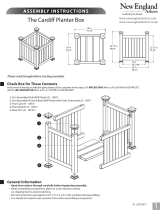
1. Posts (2) 4”x 4“ x 54” (10 cm x 10 cm x 137 cm) - 10126
2. Top Rails (2) 2“ x 3.5” x 44.5“ (5 cm x 9 cm x 113 cm) - 10103
3. Bottom Rails (2) 2“ x 3.5” x 43.5“ (5 cm x 9 cm x 110 cm) - 10104
4. Pickets (4) Length 29.25“ (74 cm) - 10105
Pickets (2) Length 30“ (76 cm)- 10107
Pickets (2) Length 31.5“ (80 cm) - 10108
Pickets (2) Length 32.75“ (83 cm) - 10109
Pickets (2) Length 34.25“ (87 cm) - 10110
Pickets (2) Length 36.25“ (92 cm) - 10111
Pickets (2) Length 38.25“ (97 cm) - 10112
Pickets (2) Length 41“ (104 cm) - 10113
5. External Post Caps (2) 4” x 4” (10 cm x 10 cm) - 10735-1
6. Post Trim Caps (2) 4” x 4” (10 cm x 10 cm)- 10737-1
7. Base Moldings (2) 5” x 5” (13 cm x 13 cm) - BM20022
8. Rail Mount Brackets (8) 2” x 3.5” (5 cm x 9 cm)- 10045
Hardware Kit (Includes):
9. 5/8” (16 mm) Self-tapping stainless Screws (24) - 20016
10. 1 1/2” (38 mm) Stainless Steel Screws (8) - 20005
11. Rail end spacers (2) 2“ x 3.5” x .5” (5 cm x 9 cm x 13 mm)- 10217
12. Tube of vinyl cement (1) - 20000
Tools You Will Need
• Cordless Drill with #2 Phillips bit
• Tape measure
• Pencil
• Level
• Shovel
• Two bags of pre-mix concrete (optional)
General Information
• Read Instructions through carefully before beginning assembly.
• When handling components, place on a non-abrasive surface
(i.e. shipping box) to avoid scratching.
• We recommend an area approx 5’x 5’ (1.5 m x 1.5 m) for unobstructed handling.
Cottage Picket Wings
Please read through before starting assembly.
Check Box for These Contents (1 Box)
In the event of missing or defective parts please call our customer service dept. at 1 800 282 9346 (Mon. to Fri. 8:00 AM to 4:00 PM EST).
(UK Tel: (44) 2038 687160 (Mon. to Fri. 1:00 PM to 10:00 PM GMT).
ASSEMBLY INSTRUCTIONS
1
1
V2.5/072617
10
Not to Scale
2
12
3
4
8
5
6
7
11
5"
(13 cm)
5" (13 cm)
8"
(20 cm)
39" (99 cm)
49"
(124 cm)
18.75"
(48 cm)
44" (112 cm)
www.newenglandarbors.com
www.newenglandarbors.co.uk
9

2
STEP ONE
Lay out one of the posts (part 1). Measure 8” (20.3 cm) from one end of
the post and put a mark. Center the rail mount bracket (part 8) on the
post, with the open end at the 8” mark. Using two screws 5/8" (16 mm) ,
fasten the bracket to the post as illustrated. Repeat this for the second
post. Note: All screws are self-tapping and require no pre-drilling.
Take one of the posts and measure 29” (73.7 cm) from the same end of the
post as in step 1. Put a mark on the post at this distance.
Slip one of the base moldings (part 7) onto the opposite end of the post
as illustrated. Slide it up the post until the top edge of the molding is at the
29” (73.7 cm) mark.
Center another rail mount bracket on the base molding, keeping the open
end of it tight against the raised lip of the base molding trim. Fasten the
bracket in place using two 1 1/2" (38 mm) screws. Repeat steps A through
C for the other post.
Note: The distance between the two brackets should measure
approximately 18 3/4” (47.6 cm) when finished.
Cottage Picket Wings Installation
A
A
B
B
C
8” (20.3 cm)
29" (73.7 cm)
C
The Cottage Picket Wings

3
STEP T WO
A
Insert the bottom rail (part 3) into the bracket on the base molding.
Make sure the holes in the rail are facing towards the second bracket
on the post. Using one screw 5/8"(16mm), secure the rail in place
through the side wall of the bracket as illustrated. Repeat this for the
opposite side wall.
Insert the top rail (part 2) into the second bracket, making sure the
larger sized holes in the rail are facing towards the bottom rail. Secure
the rail as described in the previous step. Note: The holes in the rail
are approx. 1/8” (3 mm) larger on one side to allow for proper
alignment of the pickets when mounting. Repeat steps A and B for
the remaining post and rails.
Break open one bundle of pickets (part 4). Start with the 41” (104 cm)
picket at the furthest end of the rails, and insert each one in
descending order, ending with two 29 1/4” (74 cm) pickets at the
post. Make sure the tabs on the end of the pickets “snap” into the
bottom rail. Open the second bundle of pickets and repeat for the
opposite wing panel.
A
B
C
Bottom Rail is
only routed on
the one side
Top rail is routed
on both sides:
The larger
opening faces
the bottom rail.
B
C
The Cottage Picket Wings

4
STEP THREE
A
A
B
C
B
Determine which side of your arbor the wings will be attached to.
Fasten a rail mount bracket to the outside of the arbor base molding in
the same manner as described in Step 1 (c). Note: If your arbor does not
have a base mold, install bracket directly on arbor (B). You will need to use
1/2” (13 mm) filler (A) as bottom rail is shorter to allow for base mold.
Using two 5/8" (16 mm) screws, fasten a second bracket to the outside
of the arbor post as illustrated. The distance between the brackets on
the arbor post must equal the distance measured between the brackets
on the wing post. Repeat steps A and B for the arbor side panel.
Using the distances shown, mark out each hole location on both
sides of the arbor. Dig out two 16” (41 cm) deep holes.
1/2” (13 mm) Filler
(used when no base trim is
present on the arbor p
ost).
42"
(107 cm)
49"
(124 cm)
15.5" (39.4 cm)
C
Ground Level
The Cottage Picket Wings

5
STEP FOUR
A
Lower the wing post into the hole, while slipping each rail end into the
corresponding bracket on the arbor post. check the top rail for level,
and adjust the depth of the hole if needed. Secure the rail ends to
the brackets as described in Step 2 (a), and fill in the hole (for added
stability, use pre-mix concrete). Repeat this step for the opposite wing
panel. Note: The bottom of the wing post base molding should be at
ground level when finished.
Apply a generous amount of vinyl glue around the post. Note: The vinyl
glue should be applied below the top of the picket cap level as shown.
Slip one trim cap (part 6) over the end of each post. Slide each cap
down until the top edge is level with the top of the first picket.
Apply a bead of vinyl cement to the underside of each post cap (part
5). To ensure proper attachement to the post, apply the cement to all
internal “contact” points of the cap. Place the caps onto the end of each
post and push down firmly until the end of the post “bottoms out” on
the inside of the cap. Allow a few minutes for the cement to cure.
A
B
C
B
Level
C
Vinyl glue is to be applied
below the picket level.
www.newenglandarbors.com
www.newenglandarbors.co.uk
North America Toll Free Phone: 1 800 282 9346
United Kingdom Tel: (44) 2038 687160
/