Page is loading ...

TA
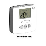
Basic Thermostat
Thermostat operation and user manual

English: Thermostat ...................................................... 4
Operation and user manual
Deutsch: Fußbodenheizung ....................................... 16
Installation und Betrieb
Français: Chauffage par le sol .................................. 28
Guide d’installation et d’utilisation
Nederlands: Vloerverwarming
........................................ 41
Installatie en bediening
Norsk Gulvvarme
........................................................ 53
Installasjon og anvendelse
Svenska: Golvvärme
........................................................ 65
Installation och användning
Dansk: Gulvvarme
........................................................ 77
Installation og betjening
Suomi: Intellis –termostaatti
................................ 89
lattialämmitykselle
Asennus- ja käyttöohje
Polski:
Instrukcja termostat
........................................ 101
montażu i obsługi
Русский
Системы подогрева полов
..................... 113
Инструкция по монтажу и эксплуатации

4
English
1. Technical specification ............................................................ 5
2. Description
..................................................................................... 6
3. Mounting and installation
...................................................... 7
4. Operation
........................................................................................ 9
4.1 Getting started
.................................................................. 9
4.2 Optional function
.............................................................. 11
4.2.1 Heat Booster
.......................................................... 11
4.2.2 External set back
................................................. 12
4.2.3 Lock
............................................................................. 12
5. Trouble shooting
........................................................................... 12
5.1 Error Codes ......................................................................... 12
5.2 Floor sensor resistances
............................................. 12
5.3 Calibration of temperature
......................................... 13
6. Factory settings
........................................................................... 15

5
1. Technical specifications
Supply voltage 230VAC, +10%,–15%,
50/60 Hz
Power consumption, average 4 VA
Main power switch 2-pole 16A
Relay output - heating cable 230V, max. 13A
Ambient temperature – operation 0 +50°C
Ambient temperature – transport –20 +50°C
Temperature range, floor sensor +5 +35°C
Temperature range, room sensor +5 +45°C
Accuracy – floor/room sensor +/– 0,5°C
Switching hysteresis 0,5°C
Control modes Floor sensor or room
sensor
Optional external control Set back function –3.5°C
Back-up for set values In non-volatile memory
Protection class IP 21
Terminals Max. 2,5 mm
2
Floor sensor NTC, 10K / 25°C.
with 3 m cable
Maximum lenght of floor 100 m, 2 x 1,5 mm
2
sensor cable (230VAC cable type)
Dimension with frame (Fig.1) H 82 x W 82
x D 54 mm
Colour Polar white RAL 9010
Approvals Semko, NF, CE

6
2. Description
TA is a basic thermostat specially designed for underfloor
heating. It provides the following features and functions:
• Heating cable control by means of an external floor
sensor or integrated room sensor.
• Load capacity of the output relay, 13A/230V (3000W)
• 2-pole main power switch
• External set back
Extra terminal which can be used as an external
closing contact to reduce the set temperature by 3,5°C
• Heat Booster
The set temperature can be increased by 5°C for
2 hours. Reverts automatically to the original
temperature setting
• Possible to lock and unlock all possible settings for
the thermostat at the touch of the buttons
• Monitoring of the floor or room sensor. Cut off the
heating output during sensor fault and with indication
(fail-safe)
• Enclosure protection class IP21 as standard
• Floor sensor with 3 meters of cable included
• The thermostat is supplied with an assembly frame
and a front for the ELJO Trend / B&J Jussi / Merten
(Plan, Smart, Arc, Atelier, M1, Antik, Termo, M-Star) /
Jung (CD, LS, AS) / Gira (ST55 Standard, E2) wall box
system. An extra front for the square sized frames
such as ELKO RS is also included
• Approved by SEMKO,NF, CE-marked

7
3. Mounting and installation
Thermostat
TA is intended for flush mounting in a standard 65 mm
wallbox. It should be positioned approximately 1,5 metres
above the floor, protected from direct sunlight and
draughts. All electrical conduits passing into the thermostat
box that contain cables must be sealed to protect the
thermostat against warm air, e.g. with a piece of insulation
in the conduit outlet.
TA can also be mounted in an external wall box. If the
thermostat will be mounted on a rough wall surface, e.g.
bricks, put a string of silicon glue under the top frame.
Assembly frame and front can be exchanged by pushing
with a screw driver on two knobs, placed on the sides of the
thermostat. (Fig. 2)
Floor sensor
The floor sensor should be installed in a separate flexible
conduit/hose for easy replacement. For best control
performance, position the floor sensor between two heating
cables as close as possible to the top floor surface. Do not
position the floor sensor tip closer than 3 cm to the heating
cable.
The floor sensor cable can be extended to 100 m with a
separate standard installation cable 2 x 1.5 mm
2
(230VAC).
In order to avoid signal disturbance resulting in a possible
malfunctioning of the thermostat, the sensor should not be
installed in a conduit together with other power carrying
cables.
Connection of the thermostat
The thermostat must be connected to 230VAC according to
the circuit diagrams. When connecting multiple heaters to
the thermostat where the combined total load is above 13A,
you are required to use a contactor or switchgear.
If the protective earth terminal, (PE) on the thermostat is
used, the incoming power cable to the heating cable shall be
connected to the common earth terminal on the thermostat,
otherwise a separate terminal connection block (not
included) must be used.

8
Product specific information for use with
floorheating systems
• Use with T2Quicknet:
Quicknet product line is approved with the thermostat
working in floor sensor mode. Be aware that the
floor sensor must be installed and activated for an
installation with Quicknet.
• Use with T2Red (T2Reflecta) self-regulating
systems.
Self-regulating heating cables have an inrush current
at start up. In order to guarantee the life time of the
thermostat, the maximum load of the self-regulating
application in nominal conditions is limited to 10A.
A 13A self-regulating load will reduce the life time of
the relay contacts.
Direct, connection – one heating cable
Remote set
back signal
Power supply
230 VAC
Floor
sensor
FP
L
N
10K
NTC
PE
SENSOR
N
L
N
L
L
N
PE
PE
Heating cable
230 VAC
Max.13A

9
Connection via contactor e.g.– 3 heating cables
4. Operation
4.1 Getting started
Thermostat controls
FP
10K
NTC
SENSOR
N
L
N
L
K1
A2
A1
135
246
LLL
PE
NNN
L
N
L1 L2 L3 N PE
Remote set
back signal
Power supply
230 VAC
Floor
sensor
Power supply to
heating cables
A
B
C
D
A: main power switch
B: OK/accept
C: “–“ down
D: “+” up

10
Display symbols
Set value for floor- or room temperature
or error code
Heating cable on
Error
Locked settings
Calibration mode
Menu number
Manual mode
Auto mode
Heat booster active
Floor- or Room sensor mode
(in room sensing mode <
> is not shown)
Note: the square moves over the different symbols when
programming. The symbol in the square indicates the active
function: manual mode, automatic mode by external signal,
booster function.
First start – set the thermostat in operation :
Push in the main < > power switch, located on the upper
part of the thermostat.
The display illuminates and shows all segments. Then it
shows the setting temperature and sensor mode. The sensor
mode is initialised automatically. If the floor sensor cable

11
is connected, it operates in floor sensor mode. If the floor
sensor cable is not connected, it operates in room sensor
mode.
After 5 sec. the thermostat checks if an external control
signal is connected.
If yes, the thermostat will be controlling according to the
set temperature and external signal. The symbol AUTO is
activated. If no, the thermostat will be controlling according
to the set temperature.
Adjust the set temperature, desired floor temperature or
room temperature, with the <
> buttons. This is an
approximate set value to get a comfort temperature on the
floor or in the room.
Heating-on symbol <
> indicates on the display when the
heating cable is on.
4.2. Optional function
4.2.1 Activating Heat booster < >
This function is used for temporary increase of the floor/
room temperature by 5°C.
Push the confirmation button <
> in 3 sec. The current
set temperature will increase by 5°C for 2 hours and this
increased temperature is shown on the display. Automatic
reverts to the set temperature after 2 hours or if the
confirmation button is pushed again in 3 sec. within the
2 hour period.
If external control is connected: Push the confirmation
button <
> in 3 sec. The thermostat will now be in
Manual mode. Push again the confirmation button < >
in 3 sec. The thermostat will go in “booster” mode and
the current set temperature will increase by 5°C for 2
hours. This increased temperature is shown on the display.
Automatic reverts to the set temperature after 2 hours or
if the confirmation button< > is pushed again in 3 sec.
within the 2 hour period.

12
4.2.2 External set back
To utilise the set-back funtion and roll back the current set
point by 3.5°C: Connect a closing contact between the FP
terminal and phase terminal e.g. a closing timer switch.
When the contact is closed and active signal present, the
symbol "P" is displayed in the upper left corner indicating
activation.
To enable manual control mode: Push the confirmation
button in 3 sec. Normal set temperature control is active.
Push again the confirmation button <
> in 3 sec. for
leaving the Manual mode to Booster mode. Push the
confirmation button
< > again 3 sec to go the AUTO mode.
4.2.3 Lock
Lock and unlock the thermostat
Possible to lock all the set possibilities for the thermostat.
(eg public buildings)
Lock: Push simultaneously < > and < > and < >
Unlock: Push simultaneously < > and < > and < >
5. Trouble shooting
5.1 Error codes
Number Error type
ER 1
Wrong floor sensor (100 kΩ)
ER 2
Short circuit on floor sensor
ER 3
Open circuit on floor sensor
ER 4
Short circuit on room sensor
ER 5
Open circuit on room sensor
ER 6
Other error
5.2 Monitoring of the temperature sensor
In the event of damage or malfunction of one of the
temperature sensors, the heating output cuts off (fail safe)
and an errorcode is displayed.

13
The floor sensor has the following temperature / resistance
values:
15°C / 15,8 kΩ
20°C / 12,5 kΩ
25°C / 10,0 kΩ
30°C / 8,04 kΩ
35°C / 6,51 kΩ
The floor sensor may be replaced by a new one. In the event
of malfunction of the room sensor the entire thermostat
must be replaced.
5.3 Calibration of temperature < >
If the desired temperature is not reached or if there is a
difference between real floor/room temperature and the set
value on the display, calibrate the thermostat.
Push OK continuously for full 6 seconds to enter following
Menu:
• Menu 1: < > read-out actual measured temperature
• Menu 2:
< > calibration of the floor/room
temperature
Menu 1:
Service read-out of actual measured temperature (only
valid in floor sensing mode) < >:
To check the actual measured temperature, push the
confirmation button for 6 sec.
In menu number 1 the
measured temperature value is
indicated on the display: in-
floor temperature in case of
floor sensing mode < >.
This value can be used to calibrate the floor surface
temperature value to the set temperature value on the
display. Push confirmation button several times (scroll
through Menu structure) for leaving the Configuration mode
to Normal mode

14
Menu 2:
Calibration of the temperature set value
After stable temperature in
floor: The set temperature
value can be calibrated
against the real floor / room
temperature. This needs to
be done using a separate
thermometer for determining the actual floor or room
temperature. The thermometer should be put on the floor
surface, sensing the floor surface temperature, or on the
wall sensing the air temperature.
Calibration of room sensor mode < >:
In room sensor mode the internal sensor value is the same
as for the set value on the display.
Push the confirmation button < > in 6 sec. to enter the
Configuration mode.
Push the confirmation button < > to enter menu
number 2.
Change the temperature value via < > buttons to the
same value shown on the reference wall thermometer.
Push confirmation button several times (scroll through
Menu structure) for leaving the Configuration mode to
Normal mode
Calibration of floor sensor mode < >:
In floor sensor mode there is a default offset value of +4°C
between the infloor sensor value and the floorsurface value
(which is the set value on the display). The read-out value in
Menu 1 can be used for set value calibration.
Push the confirmation button < > in 6 sec. to enter the
Configuration mode.
Push again the confirmation button < > to enter menu
number 2.
Change the offset value via < > buttons so that the
set temperature value will be approx. the same value shown
on the reference floor surface thermometer.

15
New offset =
T
menu 1 -
T
surface
Example: Use the floor sensor temperature value from menu
1. If this value is 27°C and the floor surface thermometer
shows 24°C, the new offset value will be 27-24 = 3.
Change the offset from 4°C to 3°C.
Push confirmation button several times (scroll through
Menu structure) for leaving the Calibration mode to Normal
mode
6. Reset to factory settings.
set value floor sensor mode < >
23°C
set value room sensor mode < >
20°C
floor sensor offset value < >
4°C
Reset: switch "off" the thermostat <
>. Press < > and
< > simultanously with switching "on" < > the
thermostat "000" is displayed. Press < > and “CLR” is
displayed. The thermostat is reset.
T
surface
T
menu1

België / Belgique
Tyco Thermal Controls
Staatsbaan 4A
3210 Lubbeek
Tel. (016) 21 35 02
Fax (016) 21 36 04
Çeská Republika
Raychem HTS s.r.o.
Novodvorská 82
14200 Praha 4
Phone 241 009 215
Fax 241 009 219
Danmark
Tyco Thermal Controls Nordic AB
Stationsvägen 4
S-430 63 Hindås
Tel. 70 11 04 00
Fax 70 11 04 01
Deutschland
Tyco Thermal Controls GmbH
Englerstraße 11
69126 Heidelberg
Tel. 0800 1818205
Fax 0800 1818204
Tyco Thermal Controls GmbH
Kölner Straße 46
57555 Mudersbach
Tel. 0271 35600-0
Fax 0271 35600-28
France
Tyco Thermal Controls SA
B.P. 90738
95004 Cergy-Pontoise Cedex
Tél. 0800 906045
Fax 0800 906003
Italia
Tyco Electronics Raychem SPA
Centro Direzionale Milanofiori
Palazzo E5
20090 Assago, Milano
Tel. (02) 57 57 61
Fax (02) 57 57 6201
Nederland
Tyco Thermal Controls b.v.
Van Heuven Goedhartlaan 121
1181 KK Amstelveen
Tel. 0800 0224978
Fax 0800 0224993
Norge
Tyco Thermal Controls Norway AS
Malerhaugveien 25
Postboks 6076 - Etterstad
0602 Oslo
Tel. +47 66 81 79 90
Fax +47 66 80 83 92
Österreich
Tyco Thermal Controls N.V. Lubbeek
Office Wien
Brown-Boveri Strasse 6/14
2351 Wiener Neudorf
Tel. (0 22 36) 86 00 77
Fax (0 22 36) 86 00 77-5
Polska
Raychem Polska Sp. z o.o.
Tyco Thermal Controls
ul. Farbiarska 69 C
02-862 Warszawa
Tel. +48 22 331 29 50
Fax +48 22 331 29 51
Schweiz / Suisse
Tyco Thermal Controls N.V.
Office Baar
Haldenstrasse 5
Postfach 2724
6342 Baar
Tel. (041) 766 30 80
Fax (041) 766 30 81
Suomi
Tyco Thermal Controls Nordic AB
Stationsvägen 4
S-430 63 Hindås
Puh. 0800 11 67 99
Telekopio 0800 11 86 74
Sverige
Tyco Thermal Controls Nordic AB
Stationsvägen 4
S-430 63 Hindås
Tel. 0301-228 00
Fax 0301-212 10
United Kingdom
Tyco Thermal Controls (UK) Ltd
3 Rutherford Road,
Stephenson Industrial Estate
Washington, Tyne & Wear
NE37 3HX, United Kingdom
Phone 0800 969013
Fax: 0800 968624
Россия и другие страны СНГ
Ty co Electronics Raychem GmbH
125315, г. Москва
Ленинградский проспект,
д. 72, офис 807
Тел : +7 (095) 721-18-88
Факс: +7 (095) 721-18-91
© Tyco Thermal Controls INST-264 PCN 1244–002938 Rev.0 06/05 Printed in Belgium on recycled paper
www.tycothermal.com
Raychem is a trademark of
Tyco Thermal Controls.
www.soldron.de
/