Danfoss Controller type AKC 114A, 115A, and 116A for controlling evaporators. Vers. 1.5x. AKM Installation guide
- Category
- Thermostats
- Type
- Installation guide

RC.1M.C2.02 → RC.1M.C3.02 11-1998
Software version 1.5x
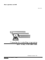
Controller for controlling evaporators
AKC 114A, 115A and 116A
ADAP-KOOL
®
Menu operation via AKM

2 Menu operation RC.1M.C3.02 © Danfoss 11/1998 AKC 114A-116A Version 1.5x
Menu list This menu function can be used together with system software type AKM. The description is
divided up into function groups that can be displayed on the PC screen. Within each group it is
now possible to show the measured values, or settings.
Regarding the use of AKM, reference is made to the AKM Manual.
Validity This menu operation was worked out in November 1998 and applies to AKC 114A, AKC
115A and AKC 116A with the following code numbers:
084B6171 and 084B6172 (AKC 114A), 084B6173 and 084B6174 (AKC 115A), 084B6175
and 084B6176 (AKC 116A) and are fitted with software version 1.5x.
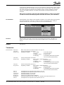
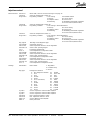
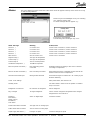
The operation is divided up into
several function groups. When a
selection has been made, push
“OK”, and you may continue from
the next display. By way of example,
the thermostat group has been
selected here.
From the measure line the different
values can be read. The values are
constantly updated.
In the list of settings the set values
can be seen. If a setting has to be
changed, select the parameter and
proceed via “OK”.
Function groups
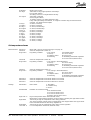
Enter the new value or move the sliding scale up or
down. The new value will apply, when “OK” is pushed.
Set the required value and push
“OK”
The various measurements can be read directly. If a graphic display of the measurements is
required, up to eight of them can be shown. Select the required measurements and push
“Trend”.
Settings There are four kinds of settings, ON/OFF settings, settings with a variable value, time settings
and “reset alarms”.
Measurements

AKC 114A-116A Version 1.5x Menu operation RC.1M.C3.02 © Danfoss 11/1998 3
Go through the individual functions one by one and make the required settings. When settings
have been made for one controller, the set values may be used as basis in the other control-
lers
of the same type
and
with the same software version
. Copy the settings by using the
function in the AKM programme, and adjust subsequently any settings where there are
deviations.
NB! If a list is required for noting down the individual settings, a printout can be made
of it with a function in the AKM programme. Read the next section, “Documentation”.
Documentation Documentation of the settings of the individual controllers can be made with the print function
in the AKM programme. Select the controller for which documentation of the settings is
required and select the “Print Settings” function (df. also the AKM Manual).
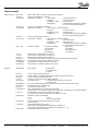
Functions Indicated below are function groups with corresponding measurements and settings. A
printout of the given settings can be made using the AKM function “Print Settings” (see
above).
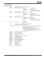
Alarms
Thermostats
Measurements AKC Error When “ON”, there is an alarm message. See page 15.
Ther.Air A Actual air temperature (section A)
RegCond.A Regulating condition: 0: No cooling 5: Start after defrost
1: Start up 6: Forced closing
2: Adaptive control 8: Sensor error
4: Defrosting 9: Modulating thermostat regulation
10: Forced cutout (melt function)
Ther.Air B Actual air temperature (section B)
RegCond.B Regulating condition: 0: No cooling 5: Start after defrost
1: Start up 6: Forced closing
2: Adaptive control 8: Sensor error
4: Defrosting 9: Modulating thermostat regulation
10: Forced cutout (melt function)
Ther.Air C Actual air temperature (section C)
RegCond.C Regulating condition: 0: No cooling 5: Start after defrost
1: Start up 6: Forced closing
2: Adaptive control 8: Sensor error
4: Defrosting 9: Modulating thermostat regulation
10: Forced cutout (melt function)
S3 A °C Air temperature at evaporator inlet (section A) (air on)
S4 A °C Air temperature at evaporator outlet (section A) (air off)
CutOut A °C Actual thermostat(s) cut-out value
CutIn A °C Actual thermostat(s) cut-in value
NightCond Status for day-/night operation (ON/OFF)
Runtime A Actual thermostat cut-in time of section A or duration of the latest finished cut-in
S3 B °C Air temperature at evaporator inlet (section B) (air on)
See page 15.

4 Menu operation RC.1M.C3.02 © Danfoss 11/1998 AKC 114A-116A Version 1.5x
S4 B °C Air temperature at evaporator outlet (section B) (air off)
CutOut B °C Actual thermostat(s) cut-out value
CutIn B °C Actual thermostat(s) cut-in value
Runtime B Actual thermostat cut-in time of section B or duration of the latest finished cut-in
S3 C °C Air temperature at evaporator inlet (section C) (air on)
S4 C °C Air temperature at evaporator outlet (section C) (air off)
CutOut C °C Actual thermostat(s) cut-out value
CutIn C °C Actual thermostat(s) cut-in value
Runtime C Actual thermostat cut-in time of section C or duration of the latest finished cut-in
Settings MainSwitch Main switch: 1: Regulation
0: Controller stop
-1: Service
Ther. Sx A Definition of thermostat sensor(s)
1: S3 is used
2: S4 is used
3: S3, S4 is used. CPT (calculated product temperature)
CutOut A °C Setting of thermostat cut-out value
MUST BE SET. Even if the thermostat has not been selected (The value is used by the
injection function).
Diff. A K Setting of thermostat differential
S4A Day % S4 weighting by day. S3 is automatically weighted. Must only be set if “Ther.Sx” = 3.
S4A Night % S4 weighting at night. S3 is automatically weighted.
S4MinLim A Setting of low S4 temperature alarm limit. The funciton is only active, if weighting between
S3 and S4 is used for the thermostat function
Ther. Sx B Definition of thermostat sensor(s)
1: S3 is used
2: S4 is used
3: S3, S4 is used. CPT (calculated product temperature)
CutOut B °C Setting of thermostat cut-out value
MUST BE SET. Even if the thermostat has not been selected (The value is used by the
injection function).
Diff. B K Setting of thermostat differential
S4B Day % S4 weighting by day. S3 is automatically weighted. Must only be set if “Ther.Sx” = 3.
S4B Night % S4 weighting at night. S3 is automatically weighted.
S4MinLim B Setting of low S4 temperature alarm limit. The funciton is only active, if weighting between
S3 and S4 is used for the thermostat function
Ther. Sx C Definition of thermostat sensor(s)
1: S3 is used
2: S4 is used
3: S3, S4 is used. CPT (calculated product temperature)
CutOut C °C Setting of thermostat cut-out value
MUST BE SET. Even if the thermostat has not been selected (The value is used by the
injection function).
Diff. C K Setting of thermostat differential
S4C Day % S4 weighting by day. S3 is automatically weighted. Must only be set if “Ther.Sx” = 3.
S4C Night % S4 weighting at night. S3 is automatically weighted.
S4MinLim C Setting of low S4 temperature alarm limit. The funciton is only active, if weighting between
S3 and S4 is used for the thermostat function
Ther. Mode Definition of thermostat function:
0: No thermostat function
1: The thermostat function is attached to section A
(cutout and cutin of section B and C will come after section A)
2: There is one thermostat function in each section
3: Modulating thermostat regulation (There is one thermostat
function in each section)
Day/Night Choose day-/night operation function
0: No night setback
1: Change between day and night operation according to signal on S6 input
2: Change between day and night operation according to internal time clock
3: Change between day and night operation according to the signal from the master
controller (Signal via DANBUSS)

AKC 114A-116A Version 1.5x Menu operation RC.1M.C3.02 © Danfoss 11/1998 5
Dt Night K Night set back value
Mo day h Time table for day-/night operation on Mondays.
End of night setback
At setting = 0 there is no night setback this day
Mo night h Time table continued:
Start (of night setback)
At setting =0 there is no night setback this day.
If day and night settings are identical, or if night is set before day, the function will be
changed. See functional description.
Tu day h As above, Tuesdays
Tu night h As above, Tuesdays
We day h As above, Wednesdays
We night h As above, Wednesdays
Th day h As above, Thursdays
Th night h As above, Thursdays
Fr day h As above, Fridays
Fr night h As above, Fridays
Sa day h As above, Saturdays
Sa night h As above, Saturdays
Su day h As above, Sundays
Su night h As above, Sundays
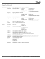
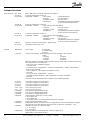
Air temperature alarms
Measurements AKC Error When “ON”, there is an alarm message. See page 15.
Ther.Air A Actual air temperature (section A)
RegCond.A Regulating condition: 0: No cooling 5: Start after defrost
1: Start up 6: Forced closing
2: Adaptive control 8: Sensor error
4: Defrosting 9: Modulating thermostat regulation
10: Forced cutout (melt function)
Ther.Air B Actual air temperature (section B)
RegCond.B Regulating condition: 0: No cooling 5: Start after defrost
1: Start up 6: Forced closing
2: Adaptive control 8: Sensor error
4: Defrosting 9: Modulating thermostat regulation
10: Forced cutout (melt function)
Ther.Air C Actual air temperature (section C)
RegCond.C Regulating condition: 0: No cooling 5: Start after defrost
1: Start up 6: Forced closing
2: Adaptive control 8: Sensor error
4: Defrosting 9: Modulating thermostat regulation
10: Forced cutout (melt function)
AlarmAir A Actual air temperature for the alarm function in section A
AlarmAir B Actual air temperature for the alarm function in section B
AlarmAir C Actual air temperature for the alarm function in section C
Settings MainSwitch Main switch: 1: Regulation
0: Controller stop
-1: Service
AlarmModeA Definition of alarm thermostat
0: No alarm thermostat
1: S3 used as alarm sensor
2: S4 used as alarm sensor
3: TherAir used as alarm sensor
High LimA °C High air temperature alarm limit (absolute value)
When there is night setback operation, the alarm limit is raised by the night setback value
High1DelA Time delay of high air temperature alarm during pull-down.
This value will apply until the actual air temperature has dropped below the “upper alarm
limit”. Thereafter shift to the time delay “High2Del A”.
High2DelA Time delay of high air temperature alarm during normal regulation
Low LimA °C Low air temperature alarm limit (absolute value)

6 Menu operation RC.1M.C3.02 © Danfoss 11/1998 AKC 114A-116A Version 1.5x
Low Del A Time delay for low air temperature alarm
AlarmModeB Definition of alarm thermostat
0: No alarm thermostat
1: S3 used as alarm sensor
2: S4 used as alarm sensor
3: TherAir used as alarm sensor
High LimB °C High air temperature alarm limit (absolute value)
When there is night setback operation, the alarm limit is raised by the night setback value
High1DelB Time delay of high air temperature alarm during pull-down.
This value will apply until the actual air temperature has dropped below the “upper alarm
limit”. Thereafter shift to the time delay “High2Del B”.
High2DelB Time delay of high air temperature alarm during normal regulation
Low LimB °C Low air temperature alarm limit (absolute value)
Low Del B Time delay for low air temperature alarm
AlarmModeC Definition of alarm thermostat
0: No alarm thermostat
1: S3 used as alarm sensor
2: S4 used as alarm sensor
3: TherAir used as alarm sensor
High LimC °C High air temperature alarm limit (absolute value)
When there is night setback operation, the alarm limit is raised by the night setback value
High1DelC Time delay of high air temperature alarm during pull-down.
This value will apply until the actual air temperature has dropped below the “upper alarm
limit”. Thereafter shift to the time delay “High2Del C”.
High2DelC Time delay of high air temperature alarm during normal regulation
Low LimC °C Low air temperature alarm limit (absolute value)
Low Del C Time delay for low air temperature alarm

AKC 114A-116A Version 1.5x Menu operation RC.1M.C3.02 © Danfoss 11/1998 7
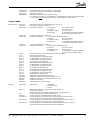
Injection control
Measurements AKC Error When “ON”, there is an alarm message. See page 15.
Ther.Air A Actual air temperature (section A)
RegCond.A Regulating condition: 0: No cooling 5: Start after defrost
1: Start up 6: Forced closing
2: Adaptive control 8: Sensor error
4: Defrosting 9: Modulating thermostat regulation
10: Forced cutout (melt function)
Ther.Air B Actual air temperature (section B)
RegCond.B Regulating condition: 0: No cooling 5: Start after defrost
1: Start up 6: Forced closing
2: Adaptive control 8: Sensor error
4: Defrosting 9: Modulating thermostat regulation
10: Forced cutout (melt function)
Ther.Air C Actual air temperature (section C)
RegCond.C Regulating condition: 0: No cooling 5: Start after defrost
1: Start up 6: Forced closing
2: Adaptive control 8: Sensor error
4: Defrosting 9: Modulating thermostat regulation
10: Forced cutout (melt function)
Rfg. Type R Reading of set refrigerant type
SuperheatA Superheat section A
SH Ref K A Actual superheat reference of the regulation
AKV OD % A Actual valve opening degree
T0 °C Evaporting temperature
S2 A °C Gas temperature at evaporator outlet
SuperheatB Superheat section A
SH Ref K B Actual superheat reference of the regulation
AKV OD % B Actual valve opening degree
S2 B °C Gas temperature at evaporator outlet
SuperheatC Superheat section A
SH Ref K C Actual superheat reference of the regulation
AKV OD % C Actual valve opening degree
S2 C °C Gas temperature at evaporator outlet
Settings MainSwitch Main switch: 1: Regulation
0: Controller stop
-1: Service
Rfg. Type Refrigerant selection:
0: No refrigerant selection 12: R142b
1: R12 13: Users def
2: R22 14: R32
3: R134a 15: R227
4: R502 16: R401A
5: R717 (ammonia) 17: R507
6: R13 18: R402A
7: R13b1 19: R404A
8: R23 20: R407C
9: R500 21: R407A
10: R503 22: R407B
11: R114 23: R410A
Inj.Ctrl A Choose expansion valve function ON/OFF
Inj.Ctrl B Choose expansion valve function ON/OFF
Inj.Ctrl C Choose expansion valve function ON/OFF
SH Max K Max. superheat reference value
SH Min K Min. superheat reference value
MOP Ctrl. Choose MOP function ON/OFF
MOP °C MOP point value

8 Menu operation RC.1M.C3.02 © Danfoss 11/1998 AKC 114A-116A Version 1.5x
Defrost control
Measurements AKC Error When “ON”, there is an alarm message. See page 15.
Ther.Air A Actual air temperature (section A)
RegCond.A Regulating condition: 0: No cooling 5: Start after defrost
1: Start up 6: Forced closing
2: Adaptive control 8: Sensor error
4: Defrosting 9: Modulating thermostat regulation
10: Forced cutout (melt function)
Ther.Air B Actual air temperature (section B)
RegCond.B Regulating condition: 0: No cooling 5: Start after defrost
1: Start up 6: Forced closing
2: Adaptive control 8: Sensor error
4: Defrosting 9: Modulating thermostat regulation
10: Forced cutout (melt function)
Ther.Air C Actual air temperature (section C)
RegCond.C Regulating condition: 0: No cooling 5: Start after defrost
1: Start up 6: Forced closing
2: Adaptive control 8: Sensor error
4: Defrosting 9: Modulating thermostat regulation
10: Forced cutout (melt function)
Def. Cond. Defrost condition: 0: Defrost not started 4: Not used
1: Pump down 5: Draining
2: Not used 6: Injection delay
3: Defrosting 7: Fan delay
S5 A °C Defrost sensor temperature in section A
S5 B °C Defrost sensor temperature in section B
S5 C °C Defrost sensor temperature in section C
DefTime m Actual defrost cut-in time or duration of the latest finished defrosting period.
MDefTime m Average value of the latest 4 defrosting periods.
AccDefSkip Total number of skipped defrosts since start
AccNo.Def Total number of sustained defrosts since start
Settings MainSwitch Main switch: 1: Regulation
0: Controller stop
-1: Service
Def. Ctrl. Choose defrost function ON/OFF
Man. Def. Manual defrost is activated when ON (changes automatically to OFF)
DOD Ctrl. Choose defrost on demand ON/OFF
Fan run Choose fan operation during defrost ON/OFF
Temp/Time Defrosting stop: 1: Temperature stop (time as security)
2: Stop on time
MaxDefTime Max. permissible defrost time in minutes (Security time on Temperature stop)
Def.Stop°C Temperature value of defrost stop
Inj.Del m Liquid injection delay time
FanOnDel m Max. permissible fan start delay after defrosting.
The delay time runs from the expiry of the delay time, if applicable, for the liquid injection
Fan On °C Temperature at which the fan starts after defrost.
Fans starts when all S5 temperatures are below the value.
DefStop Sx Definition of sensor for defrost
2: S2 3: S3
4: S4 5: S5 (default setting)
FanStopS4 Define if there should be fan stop during defrost
ON: Fans stops
FanStop°C Temperature limit for stop of fans
Stops when S4A temperature is higher than "FanStop °C"
Starts when S4A temperature is lower than "FanStop °C" - 2 K
ResAccDef Resets the two defrost counters

AKC 114A-116A Version 1.5x Menu operation RC.1M.C3.02 © Danfoss 11/1998 9
Defrost Schedules
Measurements AKC Error When “ON”, there is an alarm message. See page 15.
Ther.Air A Actual air temperature (section A)
RegCond.A Regulating condition: 0: No cooling 5: Start after defrost
1: Start up 6: Forced closing
2: Adaptive control 8: Sensor error
4: Defrosting 9: Modulating thermostat regulation
10: Forced cutout (melt function)
Ther.Air B Actual air temperature (section B)
RegCond.B Regulating condition: 0: No cooling 5: Start after defrost
1: Start up 6: Forced closing
2: Adaptive control 8: Sensor error
4: Defrosting 9: Modulating thermostat regulation
10: Forced cutout (melt function)
Ther.Air C Actual air temperature (section C)
RegCond.C Regulating condition: 0: No cooling 5: Start after defrost
1: Start up 6: Forced closing
2: Adaptive control 8: Sensor error
4: Defrosting 9: Modulating thermostat regulation
10: Forced cutout (melt function)
Settings MainSwitch Main switch: 1: Regulation
0: Controller stop
-1: Service
Mon. Sched. Choose defrost programme for Mondays 1: "Def_ Sc1"
Tue. Sched. - for Tuesdays 2: "Def_ Sc2"
Wed. Sched. - for Wednesdays 3: "Def_ Sc3"
Thu. Sched. - for Thursdays
Fri. Sched. - for Fridays
Sat. Sched. - for Saturdays
Sun. Sched. - for Sundays
No.Per Day Copy function. Number of defrosts/24 hours
FirstDef Copy function. Setting of time the 1st defrost begins
LastDef Copy function. Setting of time the last defrost begins
Auto Set. Transfer the values to the three subsequent defrost programmes.
In pos. ON they are entered in "Def_ Sc1", "Def_ Sc2" and "Def_ Sc3".
If the three defrost programmes are not to be identical, corrections subsequent must be
made in the individual programmes
No.Per Day Number of defrosts / 24 hours for defrost programme 1
Def1 Sc1 Setting of time for defrost start
Def2 Sc1 -
Def3 Sc1 -
Def4 Sc1 -
Def5 Sc1 -
Def6 Sc1 -
Def7 Sc1 -
Def8 Sc1 -
No.Per Day Number of defrosts / 24 hours for defrost programme 2
Def1 Sc2 Setting of time for defrost start
Def2 Sc2 -
Def3 Sc2 -
Def4 Sc2 -
Def5 Sc2 -
Def6 Sc2 -
Def7 Sc2 -
Def8 Sc2 -
No.Per Day Number of defrosts / 24 hours for defrost programme 3
Def1 Sc3 Setting of time for defrost start
Def2 Sc3 -
Def3 Sc3 -
Def4 Sc3 -
Def5 Sc3 -
Def6 Sc3 -
Def7 Sc3 -
Def8 Sc3 -

10 Menu operation RC.1M.C3.02 © Danfoss 11/1998 AKC 114A-116A Version 1.5x
Display Fan Railheat DI
Measurements AKC Error When “ON”, there is an alarm message. See page 15.
Ther.Air A Actual air temperature (section A)
RegCond.A Regulating condition: 0: No cooling 5: Start after defrost
1: Start up 6: Forced closing
2: Adaptive control 8: Sensor error
4: Defrosting 9: Modulating thermostat regulation
10: Forced cutout (melt function)
Ther.Air B Actual air temperature (section B)
RegCond.B Regulating condition: 0: No cooling 5: Start after defrost
1: Start up 6: Forced closing
2: Adaptive control 8: Sensor error
4: Defrosting 9: Modulating thermostat regulation
10: Forced cutout (melt function)
Ther.Air C Actual air temperature (section C)
RegCond.C Regulating condition: 0: No cooling 5: Start after defrost
1: Start up 6: Forced closing
2: Adaptive control 8: Sensor error
4: Defrosting 9: Modulating thermostat regulation
10: Forced cutout (melt function)
Fan Status of fan output (terminal 10-11)
Railheat Status of railheat output (terminal 12-13)
Settings MainSwitch Main switch: 1: Regulation
0: Controller stop
-1: Service
Disp. Ctrl Choose read-out for display:
0: No display function
1: S3 read out
2: S4 read-out
3: Ther.Air read-out
Offset K A Off-set adjustment of display signal, display A
Offset K B Off-set adjustment of display signal, display B
Offset K C Off-set adjustment of display signal, display C
Fan On % Setting of fans' ON period in percent of the “FanCycl m” time
(the function is only active in the cut-out period during night operation)
FanCycl.m Period time for total ON/OFF time
RailOnDay% During day operation: Setting of railheat ON period in percent of the “RailCycl m” time
RailOnNgt% During night operation: Setting of railheat ON period in percent of “RailCycl m” time
RailCycl m Period time for total ON/OFF time
DI Alarm Choose alarm function ON/OFF
DI Text Select the alarm text:
0: DI alarm
1: Door alarm
2: Safety cutout
3: Fan failure
4: Leak alarm
DI Delay m Time delay from the alarm is registered until executed

AKC 114A-116A Version 1.5x Menu operation RC.1M.C3.02 © Danfoss 11/1998 11
Alarm destinations
Measurements AKC Error When “ON”, there is an alarm message. See page 15.
Ther.Air A Actual air temperature (section A)
RegCond.A Regulating condition: 0: No cooling 5: Start after defrost
1: Start up 6: Forced closing
2: Adaptive control 8: Sensor error
4: Defrosting 9: Modulating thermostat regulation
10: Forced cutout (melt function)
Ther.Air B Actual air temperature (section B)
RegCond.B Regulating condition: 0: No cooling 5: Start after defrost
1: Start up 6: Forced closing
2: Adaptive control 8: Sensor error
4: Defrosting 9: Modulating thermostat regulation
10: Forced cutout (melt function)
Ther.Air C Actual air temperature (section C)
RegCond.C Regulating condition: 0: No cooling 5: Start after defrost
1: Start up 6: Forced closing
2: Adaptive control 8: Sensor error
4: Defrosting 9: Modulating thermostat regulation
10: Forced cutout (melt function)
Settings MainSwitch Main switch: 1: Regulation
0: Controller stop
-1: Service
Network ON: When alarms are registered via PC or Gateway printer
OFF: When alarms are registered via AKA 21, only
Set the priority for the following alarm texts (choose between 1, 2, 3 or 0. They have the following meaning:)
1: Alarm at relay output + DANBUSS
message
2: DANBUSS
message only
3: Alarm at relay output + DANBUSS
message, but the DO2
output on a master gateway will not be activated
0: No alarm and no DANBUSS
message
The individual alarms are explained in more detail on page 15.
StandbyMod (Regulation is stopped via the main switch)
RfgNoSelec (No selection of refrigerant)
RfgChanged (Changed refrigerant)
ChClockSet (Check AKC clock settings)
DI Alarm (DI alarm)
AI Alarm (Too high or too low level on analog input)
Overfloat (Overfilled evaporator)
LowS4Temp (Too low S4 temperature)
HighAirTem (Too high air temperature)
LowAirTem (Too low air temperature)
DefPerExce (Max. defrosting period exceeded)
FanDelExce (Max. fan delay exceeded)
230VDefInp (Wrong defrost demand)
AKS32Error (AKS 32 sensor error)
S2 Error (S2 sensor error)
S3 Error (S3 sensor error)
S4 Error (S4 sensor error)
S5 Error (S5 sensor error)
Liq.Supply (Flashgas/liquid supply)

12 Menu operation RC.1M.C3.02 © Danfoss 11/1998 AKC 114A-116A Version 1.5x
Extended functions
Measurements AKC Error When “ON”, there is an alarm message. See page 15.
Ther.Air A Actual air temperature (section A)
RegCond.A Regulating condition: 0: No cooling 5: Start after defrost
1: Start up 6: Forced closing
2: Adaptive control 8: Sensor error
4: Defrosting 9: Modulating thermostat regulation
10: Forced cutout (melt function)
Ther.Air B Actual air temperature (section B)
RegCond.B Regulating condition: 0: No cooling 5: Start after defrost
1: Start up 6: Forced closing
2: Adaptive control 8: Sensor error
4: Defrosting 9: Modulating thermostat regulation
10: Forced cutout (melt function)
Ther.Air C Actual air temperature (section C)
RegCond.C Regulating condition: 0: No cooling 5: Start after defrost
1: Start up 6: Forced closing
2: Adaptive control 8: Sensor error
4: Defrosting 9: Modulating thermostat regulation
10: Forced cutout (melt function)
ExtRef K Display of reference (input signal + displacement)
AI Input % Input signal value in per cent
Settings MainSwitch Main switch: 1: Regulation
0: Controller stop
-1: Service
Language Selection of language. Three languages have been entered in the controller.
Either: Or:
0: English 0: English
1: German 3: Danish
2: Franch 4: Spanish
NB! If this setting is changed, another “Upload” must be made of the controller's data for the
AKM programme. You do it this way:
- Select one of the available languages.
- Close the menu
- Proceed to menu “Configuration” - “Advanced Configuration”- “Delete description file”
- Push file type “Default”
- Select controller's code number and software version
- Push “OK”
- Proceed to menu “Configuration” - “Upload”
- Complete the fields “Network”, “Net configuration” and “AKC description”
- Push “OK”
Texts will now be obtained from the controller in the required language.
S2 A Corr. Correction of signal from S2 A sensor
S3 A Corr. Correction of signal from S3 A sensor
S4 A Corr. Correction of signal from S4 A sensor
S5 A Corr. Correction of signal from S5 A sensor
S2 B ....S5 B Same as for S2 A to S5 A
S2 C ... S5 C Same as for S2 A to S5 A
Liq.AlDelA Time delay for flashgas/liquid alarm
Liq.AlDelB Time delay for flashgas/liquid alarm
Liq.AlDelC Time delay for flashgas/liquid alarm
OutputCtrl Output functions when tere is forced control
1: Fan outlet is ON
2: Fan outlet is OFF
3: All outlets are OFF and alarm thermostat function is stopped
FanStopS5 Define fan stop function ON or OFF
FanStop°C Temperature limit for fan stop (the fans are stopped when the S5A temperatures is higher
than this value. The fans will start again when S5A is lower than “FanStop°C” - 2K)
ExtRefSig Definition for extern AL reference signal
1: 0 - 10 V signal
2: 2 - 10 V signal
ExtRefTemp Displacement to be produced by max. reference signal (10 V)
(With setting = 0 the function is OFF)

AKC 114A-116A Version 1.5x Menu operation RC.1M.C3.02 © Danfoss 11/1998 13
AI MaxLim% Upper alarm limit. Set in percentage of input signal
AI MinLim % Lower alarm limit. Set in percentage of input signal
AI Delay m Time delay for alarm
ON-InpMode Definition of AKC-ON input (terminals 32-33)
0: Connection not used, as the regulation is controlled by the gateway's override function
1: Connection must be made (when voltage is interrupted, the valve closes)
Service mode
Measurements AKC Error When “ON”, there is an alarm message. See page 15.
Ther.Air A Actual air temperature (section A)
RegCond.A Regulating condition: 0: No cooling 5: Start after defrost
1: Start up 6: Forced closing
2: Adaptive control 8: Sensor error
4: Defrosting 9: Modulating thermostat regulation
10: Forced cutout (melt function)
Ther.Air B Actual air temperature (section B)
RegCond.B Regulating condition: 0: No cooling 5: Start after defrost
1: Start up 6: Forced closing
2: Adaptive control 8: Sensor error
4: Defrosting 9: Modulating thermostat regulation
10: Forced cutout (melt function)
Ther.Air C Actual air temperature (section C)
RegCond.C Regulating condition: 0: No cooling 5: Start after defrost
1: Start up 6: Forced closing
2: Adaptive control 8: Sensor error
4: Defrosting 9: Modulating thermostat regulation
10: Forced cutout (melt function)
P0 Bar Suction pressure (measured with P0 pressure transmitter)
T0 °C Evaporating temperature
S2 A °C Gas temperature at evaporator outlet
S3 A °C Air temperature at evaporator inlet
S4 A °C Air temperature at evaporator outlet
S5 A °C Temperature at defrost sensor
S2 B °C Gas temperature at evaporator outlet
S3 B °C Air temperature at evaporator inlet
S4 B °C Air temperature at evaporator outlet
S5 B °C Temperature at defrost sensor
S2 C °C Gas temperature at evaporator outlet
S3 C °C Air temperature at evaporator inlet
S4 C °C Air temperature at evaporator outlet
S5 C °C Temperature at defrost sensor
S6 input Statement of S6 inlet (terminal 60 - 61)
Def. Start Statement of defrost start signal (terminal 30 - 31)
ON input Statement of forced closing input (terminal 32 - 33)
DI input Statement of DI input
Ext.Ref. V Voltage signal on "Ext.Ref." input
Settings MainSwitch Main switch: 1: Regulation
0: Controller stop
-1: Service
Man. Ctrl. ON: Manual control is permitted when “Main Switch” = -1.
NOTE! No monitoring
When manal setting is finished, setting must be changed to OFF.
Fan Forced operation of fan outlet (terminal 10-11)
Railheat Forced operation of railheat outlet (terminal 12-13)
AKV OD% A Forced operation of expansion valve opening degree (terminal 14-15)
(Fan must be operating during forced control operation)
AKV OD% B Forced operation of expansion valve opening degree (terminal 110-111)
(Fan must be operating during forced control operation)
AKV OD% C Forced operation of expansion valve opening degree (terminal 120-121)
(Fan must be operating during forced control operation)

14 Menu operation RC.1M.C3.02 © Danfoss 11/1998 AKC 114A-116A Version 1.5x
DO Output Forced operation of DO Output (terminal 16-17)
Compressor Forced operation of compressor outlet (terminal 18-19)
Alarm Forced opeation of alarm outlet (terminal 20 - 21)
ON: Relay switch closed (no alarm)
OFF: Relay switch interrupted (alarm)
Defrost A Forced operation of defrost outlet (terminal 22-23)
Defrost B Forced operation of defrost outlet (terminal 112-113)
Defrost C Forced operation of defrost outlet (terminal 122-123)
AKM menu "For DANFOSS only"
This menu contains data and setting values for special internal controller functions.
Do not chage the stated values.

AKC 114A-116A Version 1.5x Menu operation RC.1M.C3.02 © Danfoss 11/1998 15
Alarms
Alarms may be acknowledged one by one selecting
one, and then pushing “OK”.
An alarm message will now appeat. e.g.:
Push "OK" to acknowledge.
The following alarm messages may occur:
The menu display for alarms shows the active alarms. Dots will appear at the top of the menu for as long
as data is being obtained.
Alarm message Meaning Action/Cause
S2 Error ( ) S2 sensor error Check sensor connection / sensor resistance
S3 Error ( ) S3 sensor error Check sensor connection / sensor resistance
S4 Error ( ) S4 sensor error Check sensor connection / sensor resistance
S5 Error ( ) S5 sensor error Check sensor connection / sensor resistance
AKS 32 Error AKS 32 sensor error Check sensor connection
High Air Temp ( ) Too high air temperature
Low Air Temp ( ) Too high air temperature
Low S4 Temp. A Too low S4 temperature
Overfloated evaporator ( ) Overfilled evaporator
Max Def. period exceeded ( ) Max. defrosting period Defrosting finished according to time not as selected
exceeded according to temperature
Max fan del time exceeded ( ) Max. fan delay exceeded When defrost has been completed, the fan start will be
based on time and not on temperature
230 Volt on Def.Start input Wrong defrost demand Active defrost signal on terminal 30 - 31 contrary to just
finished defrosting
Check clock settings After power failure, time must be set.
Standby mode The main switch is either set in the position “Controller
stop” or “Service”.
Refrigerant not selected No selection of refrigerant Select refrigerant
Rfg. Changed Changed refrigerant Check choosen refrigerant. Regulation with changed
refrigerant has come into force.
DI Alarm / Alarm on digital input Check the function
Door Alarm /
Safety Cutout /
Fan failure /
Leak alarm
AI Max alarm limit exceeded Too high level on analog input
Al Min alarm limit exceeded Too low level on analog input
Liquid supply fault alarm ( ) Flashgas or liquid Check for flashgas or liquid

16 Menu operation RC.1M.C3.02 © Danfoss 11/1998 AKC 114A-116A Version 1.5x
Danfoss can accept no responsibility for possible errors in catalogues, brochures and other printed material. Danfoss reserves the right to alter its products without notice. This also applies to products
already on order provided that such alternations can be made without subsequential changes being necessary in specifications already agreed.
All trademarks in this material are property of the respecitve companies. Danfoss and Danfoss logotype are trademarks of Danfoss A/S. All rights reserved.
AC-RDT
-
 1
1
-
 2
2
-
 3
3
-
 4
4
-
 5
5
-
 6
6
-
 7
7
-
 8
8
-
 9
9
-
 10
10
-
 11
11
-
 12
12
-
 13
13
-
 14
14
-
 15
15
-
 16
16


Danfoss Controller type AKC 114A, 115A, and 116A for controlling evaporators. Vers. 1.5x. AKM Installation guide
- Category
- Thermostats
- Type
- Installation guide
Ask a question and I''ll find the answer in the document
Finding information in a document is now easier with AI
Related papers
-
Danfoss Controller type AKC 114, 115, and 116 for controlling evaporators. Vers. 1.5x. AKM Installation guide
-
-
-
-
-
-
-
-
-