Supermicro H8DA6+-F User manual
- Category
- Server/workstation motherboards
- Type
- User manual
This manual is also suitable for

®
SUPER
H8DA6+
H8DA6+-F
H8DAI+
H8DAI+-F
USER’S MANUAL
Revision 1.0c

The information in this User’s Manual has been carefully reviewed and is believed to be accurate.
The vendor assumes no responsibility for any inaccuracies that may be contained in this document,
makes no commitment to update or to keep current the information in this manual, or to notify any
person or organization of the updates. Please Note: For the most up-to-date version of this
manual, please see our web site at www.supermicro.com.
Super Micro Computer, Inc. ("Supermicro") reserves the right to make changes to the product
described in this manual at any time and without notice. This product, including software and
documentation, is the property of Supermicro and/or its licensors, and is supplied only under a
license. Any use or reproduction of this product is not allowed, except as expressly permitted by
the terms of said license.
IN NO EVENT WILL SUPERMICRO BE LIABLE FOR DIRECT, INDIRECT, SPECIAL, INCIDENTAL,
SPECULATIVE OR CONSEQUENTIAL DAMAGES ARISING FROM THE USE OR INABILITY TO
USE THIS PRODUCT OR DOCUMENTATION, EVEN IF ADVISED OF THE POSSIBILITY OF
SUCH DAMAGES. IN PARTICULAR, SUPERMICRO SHALL NOT HAVE LIABILITY FOR ANY
HARDWARE, SOFTWARE, OR DATA STORED OR USED WITH THE PRODUCT, INCLUDING THE
COSTS OF REPAIRING, REPLACING, INTEGRATING, INSTALLING OR RECOVERING SUCH
HARDWARE, SOFTWARE, OR DATA.
Any disputes arising between manufacturer and customer shall be governed by the laws of Santa
Clara County in the State of California, USA. The State of California, County of Santa Clara shall
be the exclusive venue for the resolution of any such disputes. Super Micro's total liability for all
claims will not exceed the price paid for the hardware product.
FCC Statement: This equipment has been tested and found to comply with the limits for a Class
A digital device pursuant to Part 15 of the FCC Rules. These limits are designed to provide
reasonable protection against harmful interference when the equipment is operated in a commercial
environment. This equipment generates, uses, and can radiate radio frequency energy and, if not
installed and used in accordance with the manufacturer’s instruction manual, may cause harmful
interference with radio communications. Operation of this equipment in a residential area is likely
to cause harmful interference, in which case you will be required to correct the interference at your
own expense.
California Best Management Practices Regulations for Perchlorate Materials: This Perchlorate
warning applies only to products containing CR (Manganese Dioxide) Lithium coin cells. “Perchlorate
Material-special handling may apply. See www.dtsc.ca.gov/hazardouswaste/perchlorate”
WARNING: Handling of lead solder materials used in this
product may expose you to lead, a chemical known to
the State of California to cause birth defects and other
reproductive harm.
Manual Revision 1.0c
Release Date: April 15, 2010
Unless you request and receive written permission from SUPER MICRO COMPUTER, you may not
copy any part of this document.
Information in this document is subject to change without notice. Other products and companies
referred to herein are trademarks or registered trademarks of their respective companies or mark
holders.
Copyright © 2010 by SUPER MICRO COMPUTER INC.
All rights reserved.
Printed in the United States of America

Preface
iii
Preface
About This Manual
This manual is written for system integrators, PC technicians and
knowledgeable PC users. It provides information for the installation and use
of the H8DA6+/I+(-F). This series includes the following serverboards and
characteristics:
H8DA6+-F H8DA6+ H8DAi+-F, H8DAi+
Embeded IPMI Yes Yes
Onbard SAS2 Yes Yes
The H8DA6+/I+(-F) is based on the AMD® SR5690/SP5100 chipset and supports
dual AMD Socket F type processors with up to 128 GB of DDR2-800/667/533
registered ECC SDRAM.
Please refer to the motherboard specifi cations pages on our web site for updates on
supported processors (http://www.supermicro.com/aplus/). This product is intended
to be professionally installed.
Manual Organization
Chapter 1 includes a checklist of what should be included in your motherboard
box, describes the features, specifi cations and performance of the motherboard
and provides detailed information about the chipset.
Chapter 2 begins with instructions on handling static-sensitive devices. Read this
chapter when installing the processor(s) and memory modules and when installing
the motherboard in a chassis. Also refer to this chapter to connect the hard disk
drives, the various ports, and the power and reset buttons and the system LEDs.
If you encounter any problems, see Chapter 3, which describes troubleshooting
procedures for the video, the memory and the setup confi guration stored in CMOS.
For quick reference, a general FAQ (Frequently Asked Questions) section is
provided. Instructions are also included for contacting technical support. In addition,
you can visit our web site for more detailed information.
Chapter 4 includes an introduction to BIOS and provides detailed information on
running the CMOS Setup utility.
Appendix A provides BIOS Error Beep Code Messages.
Appendix B lists BIOS POST Checkpoint Codes.

H8DA6+/I+(-F) Serverboard User’s Manual
iv
Table of Contents
Chapter 1 Introduction
1-1 Overview ............................................................................................................ 1
Checklist ............................................................................................................. 1
1-2 Contacting Supermicro ....................................................................................... 2
1-3 Chipset Overview ............................................................................................. 10
AMD SR5690/SP5100 Processor .................................................................... 10
HyperTransport Technology ............................................................................. 10
1-4 PC Health Monitoring ....................................................................................... 10
1-5 Power Confi guration Settings............................................................................11
1-6 Power Supply ................................................................................................... 12
1-7 Super I/O .......................................................................................................... 13
Chapter 2 Installation
2-1 Static-Sensitive Devices ..................................................................................... 1
Precautions ........................................................................................................ 1
Unpacking .......................................................................................................... 1
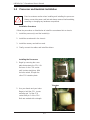
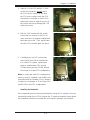
2-2 Processor and Heatsink Installation................................................................... 2
2-3 Mounting the Motherboard into a Chassis ......................................................... 4
2-4 Installing Memory ............................................................................................... 5
2-5 PCI Expansion Cards ......................................................................................... 6
2-6 I/O Port and Control Panel Connections ........................................................... 7
Front Control Panel ............................................................................................ 7
2-7 Connector Defi nitions ........................................................................................ 8
Power Connectors ........................................................................................ 8
PW_ON Connector ........................................................................................ 8
Reset Connector ........................................................................................... 8
Overheat/Fan Fail LED (OH)......................................................................... 8
NIC2 (LAN2) LED .......................................................................................... 9
NIC1 (LAN1) LED .......................................................................................... 9
HDD LED ....................................................................................................... 9
Power On LED .............................................................................................. 9
NMI Button .................................................................................................... 9
LAN1/2 (Ethernet Ports) ................................................................................ 9
Universal Serial Bus Ports .......................................................................... 10
USB Headers .............................................................................................. 10
Fan Headers ................................................................................................ 10
Serial Ports .................................................................................................. 10

v
Table of Contents
SGPIO ..........................................................................................................11
SMBus Header .............................................................................................11
Wake-On-LAN ..............................................................................................11
Power I2C .....................................................................................................11
Overheat LED ...............................................................................................11
Chassis Intrusion ........................................................................................ 12
Power LED/Speaker .................................................................................... 12
ATX PS/2 Keyboard and PS/2 Mouse Ports ............................................... 12
Compact Flash Card PWR Connector ........................................................ 12
(Back_Panel) High Defi nition Audio (HD Audio) ........................................ 13
CD & 10-pin Audio Headers ........................................................................ 13
Video Connector .......................................................................................... 13
IEEE 1394 Connection ................................................................................ 14
JS_IBTN1 Connection ................................................................................. 14
2-8 Jumper Settings ............................................................................................... 15
Explanation of Jumpers ................................................................................... 15
CMOS Clear ................................................................................................ 15
I2C to PCI-Express Slot .............................................................................. 16
Watch Dog Enable/Disable ......................................................................... 16
TPM Support Enable ................................................................................... 16
VGA Enable/Disable .................................................................................... 16
SAS Enable/Disable .................................................................................... 16
LAN Enable/Disable ................................................................................... 17
Compact Flash Master/Slave Select ........................................................... 17
Audio Mode Select ...................................................................................... 17
IEEE 1394 Firewire Enable/Disable ........................................................... 17
2-9 Onboard Indicators ........................................................................................... 18
LAN1/LAN2 LEDs ........................................................................................ 18
Dedicated IPMI LAN LEDs .......................................................................... 18
BMC Heartbeat LED ................................................................................... 18
Power LED .................................................................................................. 18
SAS2008 Heartbeat LED ............................................................................ 18
2-10 Floppy, IDE, SAS and SATA Drive Connections .............................................. 19
IDE Connectors ........................................................................................... 19
SATA Ports .................................................................................................. 20
SAS Ports .................................................................................................... 20
2-11 Enabling SATA RAID ........................................................................................ 20
Serial ATA (SATA)............................................................................................. 20

H8DA6+/I+(-F) Serverboard User’s Manual
vi
Installing the OS/SATA Driver .......................................................................... 21
Building a Driver Diskette ............................................................................ 21
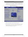
Enabling SATA RAID in the BIOS .................................................................... 21
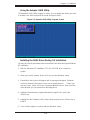
Using the Adaptec RAID Utility ........................................................................ 23
Installing the RAID Driver During OS Installation ............................................ 23
2-12 Installing Drivers ............................................................................................... 24
Supero Doctor III .............................................................................................. 25
Chapter 3 Troubleshooting
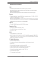
3-1 Troubleshooting Procedures .............................................................................. 1
Before Power On ............................................................................................... 1
No Power ........................................................................................................... 1
No Video ............................................................................................................ 2
Memory Errors .................................................................................................. 2
Losing the System’s Setup Confi guration .......................................................... 2
3-2 Technical Support Procedures ........................................................................... 3
3-3 Frequently Asked Questions .............................................................................. 3
3-4 Returning Merchandise for Service.................................................................... 4
Chapter 4 BIOS
4-1 Introduction ......................................................................................................... 1
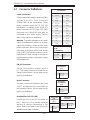
4-2 Main Menu ......................................................................................................... 2
4-3 Advanced Settings Menu ................................................................................... 2
4-4 Security Menu .................................................................................................. 16
4-5 Boot Menu ........................................................................................................ 16
4-6 Exit Menu ......................................................................................................... 17
Appendix A BIOS Error Beep Codes
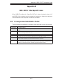
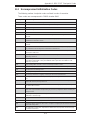
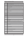
Appendix B BIOS POST Checkpoint Codes
B-1 Uncompressed Initialization Codes .................................................................... 1
B-2 Bootblock Recovery Codes ................................................................................ 2
B-3 Uncompressed Initialization Codes .................................................................... 3

Chapter 1: Introduction
1-1
Chapter 1
Introduction
1-1 Overview
Checklist
Congratulations on purchasing your computer motherboard from an acknowledged
leader in the industry. Supermicro boards are designed with the utmost attention to
detail to provide you with the highest standards in quality and performance.
Please check that the following items have all been included with your motherboard.
If anything listed here is damaged or missing, contact your retailer.
One (1) H8DA6+/I+(-F) serverboard (either H8DA6+-F, H8DA6+, H8DAi+-F or
•
H8DAi+)
One (1) CD containing drivers and utilities
•
One (1) 9-pin Serial Port cable (CBL-0010L)•
One (1) ATA 66/100 IDE LP cable (CBL-0036L-03)•
Four (4) (Six (6) for H8DAi+(-F) boards) 2ft. Amphenol, SATA cables (CBL-•
0044L)
Two (2) 50cm IPASS TO 4 SATA cables (CBL-0097L-02) (H8DA6+(-F) boards
•
only)
One (1) Standard I/O shield (MCP-260-00025-0N)
•
Two (2) Retention Brackets (BKT-0012L)•

1-2
H8DA6+/I+(-F) Serverboard User’s Manual
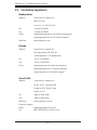
1-2 Contacting Supermicro
Headquarters
Address: Super Micro Computer, Inc.
980 Rock Ave.
San Jose, CA 95131 U.S.A.
Tel: +1 (408) 503-8000
Fax: +1 (408) 503-8008
Email: [email protected] (General Information)
[email protected] (Technical Support)
Web Site: www.supermicro.com
Europe
Address: Super Micro Computer B.V.
Het Sterrenbeeld 28, 5215 ML
's-Hertogenbosch, The Netherlands
Tel: +31 (0) 73-6400390
Fax: +31 (0) 73-6416525
Email: [email protected] (General Information)
[email protected] (Technical Support)
[email protected] (Customer Support)
Asia-Pacifi c
Address: Super Micro Computer, Inc.
4F, No. 232-1, Liancheng Rd.
Chung-Ho 235, Taipei County
Taiwan, R.O.C.
Tel: +886-(2) 8226-3990
Fax: +886-(2) 8226-3991
Web Site: www.supermicro.com.tw
Technical Support:
Email: [email protected]
Tel: 886-2-8228-1366, ext.132 or 139

Chapter 1: Introduction
1-3
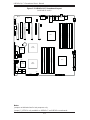
Figure 1-1. H8DA6+/I+(-F) Serverboard Image
Note: The H8DAi+(-F) serverboard does not have onboard SAS support integrated.

1-4
H8DA6+/I+(-F) Serverboard User’s Manual
Notes:
Jumpers not indicated are for test purposes only.
Jumper JS_IBTN1 is only available on H8DA6+-F and H8DA6+ serverboards.
Figure 1-2. H8DA6+/I+(-F) Serverboard Layout
(not drawn to scale)
JWF1
JUSB5
JUSB4
JWP1
JAUDIO1
CD1
J138
JPW2
JPW3
JF1
JSMB1
JWOL
JBT1:
CMOS
CLEAR
JPS1
JPI1
JPB
JWD
JPL1
JPG1
JPT1
JD1
JPI2C
DP5 LED
BATTERY
SATA5
SATA4
SATA0 SATA2
SATA1 SATA3
JLPC80
JUSB2
FAN6
FAN5
FAN8
FAN7
FAN4
FAN3
FAN2 FAN1
JL1
JL2
JI2C2
JI2C1
JOH1
1
JCF1
SLOT3 PCI-E 2.0 X16
SLOT2 PCI 33MHz
SLOT1 PCI-E 2.0 X16
AUDIO FP
CD-in
1394_21394_1
KB/
MOUSE
IPMI_LAN
USB0/1
CPU1/DIMM1B
CPU1/DIMM1A
CPU1/DIMM2A
CPU1/DIMM2B
COM1
CPU2
CPU1/DIMM4B
CPU1/DIMM3A
CPU1/DIMM3B
CPU1
CPU1/DIMM4A
CPU2/DIMM4A
CPU2/DIMM4B
VGA
CPU2/DIMM3A
CPU2/DIMM3B
CPU2/DIMM2A
LAN1
CPU2/DIMM2B
LAN2
CPU2/DIMM1A
CPU2/DIMM1B
SLOT7 PCI-E 2.0 X16
SLOT6 PCI-E 2.0 X4 (IN X8 SLOT)
SLOT5 PCI-E 2.0 X16
SLOT4 PCI-E 2.0 X4 (IN X8 SLOT)
IDE#1
SAS 4~7SAS 0~3
COM2
USB2/3/4/5
T-SGPIO2
T-SGPIO1
AMD
SR5690
SAS
LSI2008
AMD
SR5690
AMD
SP5100
BMC
DP4 LED
LEDS2
JS-IBTN1

Chapter 1: Introduction
1-5
H8DA6+/I+(-F) Quick Reference
Jumper Description Default Setting
JBT1 CMOS Clear (See Section 2-7)
JCF1 Compact Flash Master/Slave Closed (Master)
JI
2
C1/JI
2
C2 I
2
C to PCI-E Slot Enable/Disable Both Closed (Enabled)
JL2 Audio Mode Select Open (HD Mode)
JPG1 VGA Enable/Disable Pins 1-2 (Enabled)
JPI1 IEEE 1394 Firewire Enable
Pins 1-2 (Enabled)
JPL LAN Enable/Disable Pins 1-2 (Enabled)
JPS1 SAS Controller Enable/Disable Pins 1-2 (Enabled)
JPT1 Trusted Platform Modules Jumper
Pins 1-2 (Enabled)
JWD Watch Dog Pins 1-2 (Reset)
LED Description
LAN Ports LEDs for the LAN Ethernet ports
Dedicated IPMI LAN LEDs for the dedicated IPMI LAN Ethernet port
DP5 LED for BMC Activity
DP4 Power LED
LEDS2 SAS2008 heartbeat LED

1-6
H8DA6+/I+(-F) Serverboard User’s Manual
Connector Description
1394_1/1394_2 IEEE 1394 Firwire connectors
COM1/COM2 COM1 Serial Port/Header
FAN 1-8 Chassis/CPU Fan Headers
(HD) Audio/CD-In/FP Audio 7.1 Channel High Defi nition Audio (JAUDIO1)/CD-In (CD-1)/Front
Panel Audio (J138)
IDE#1 IDE Drive Connector
IPMI LAN Dedicated IPMI LAN Port
JD1 Speaker Header
JF1 Front Panel Connector
JS_IBTN1 AOC-IMRRAKEY-2008-LSI Connector/
JL1 Chassis Intrusion Header
JOH1 Overheat Warning Header
JPI2C Power I
2
C Header
JPW1 24-pin Main ATX Power Connector
JPW2/3 +12V 8-pin CPU Power Connectors
JSMB1 (SMBus) System Management Bus Header
JWF1 Compact Flash Card Power Connector
JWOL Wake-On-LAN Header
LAN1/2 Gigabit Ethernet (RJ45) Ports
PS2 Mouse/Keyboard PS2 Mouse/Keyboard connectors
SAS0~3, SAS4~7 SAS Ports
SATA0 ~ SATA5 SATA Ports
T-SGPIO-1/TSGPIO-2 Serial General Purpose Input/Output Headers
USB0/1, USB2/3/4/5, JUSB2,
JUSB4/5
Universal Serial Bus (USB) Ports, Headers, Type-A Ports
VGA VGA Connector

Chapter 1: Introduction
1-7
Motherboard Features
CPU
Dual AMD Opteron 2000 series (Socket F type) processors•
Note: Supports 237x, 238x, 235x and 24xx processors. Please refer to our web site for further
details on supported processors.
Note: This serverboard requires that two CPUs be installed to have full function support.
Memory
Sixteen single/dual channel DIMM slots supporting up to 128 GB of DDR2-•
800/667/533 registered ECC SDRAM
Note: Due to a CPU specifi cation, fully populating DIMM slots with DDR2-800/667 memory downgrades
the speed to DDR2 533 MHz (see our web site for possible updates to this). Refer to Section 2-4 before
installing memory and our web site for recommended DIMMs.
Chipset
Two AMD SR5690 and one AMD SP5100 chipsets•
Expansion Slots
Four (4) PCI-Express x16 Gen 2 slots•
Two (2) PCI-Express x4 (in x8) Gen 2 slots•
One (1) PCI slot•
BIOS
16 Mb AMIBIOS•
®
SPI Flash ROM
APM 1.2, DMI 2.3, PCI 2.2, ACPI 1.0 (ACPI 2.0 is BIOS supported), SMBIOS 2.3,
•
Plug and Play (PnP), BIOS Rescue hot keys, USB Keyboard support, Hardware
BIOS Virus protection, RTC Wakeup
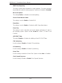
PC Health Monitoring
Onboard voltage monitors•
Fan status monitor with fi rmware/software on/off and speed control•
Watch Dog•
Environmental temperature monitoring via BIOS•
Power-up mode control for recovery from AC power loss•
System resource alert (via included utility program)•
Auto-switching voltage regulator for the CPU core•
CPU thermal trip support•
I•
2
C temperature sensing logic

1-8
H8DA6+/I+(-F) Serverboard User’s Manual
ACPI Features
Microsoft OnNow•
Slow blinking LED for suspend state indicator•
BIOS support for USB keyboard•
Wake-On-LAN (WOL) and Wake-On-Ring (WOR) headers•
Internal/external modem ring-on•
Onboard I/O
On-chip SATA controller supporting six (6) SATA ports (RAID 0, 1, 10 sup-•
ported)
One (1) UDMA IDE 133/100 port
•
LSI 2008 8-port SAS2 controller supports two (2) I-Pass connectors (H8DA6+ •
and H8DA6+-F only) and supports RAID 0, 1, 10 and JBOD. Optional RAID-5
Support with AOC-IMRRAKEY-2008-LSI key.
Two (2) IEEE 1394 single ports w/header
•
Two (2) Fast UART 16550 compatible serial port (one header and one port)•
Ten (10) USB (Universal Serial Bus 2.0) ports (6x rear, 2x header, 2x type A)•
Onboard Intel•
®
82576 dual port Ethernet controller for 10/100/1000Base-T sup-
port for two (2) LAN ports
One (1) dedicated IPMI LAN port (H8DA6+-F and H8DAi+-F only)
•
Onboard Matrox•
®
G200 graphics controller (with 16 MB DDR2 memory) sup-
ports one (1) VGA port
7.1 HD Audio ports (ALC888 chip)
•
Other
Onboard power LED•
Chassis intrusion detection•
CD Utilities
BIOS fl ash upgrade utility•
Super Doctor III•
IPMI 1.5 / 2.0 (Optional)•
Dimensions
Extended ATX form: 13.68" x 13.05" (347 x 331 mm)•

Chapter 1: Introduction
1-9
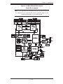
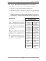
Figure 1-3. AMD SR5690/SP5100 Chipset:
System Block Diagram
Note: This is a general block diagram and may not exactly represent
the features on your motherboard. See the previous pages for the
actual specifi cations of your motherboard.
DDR2
HT 1 HT 1
DDR2
H
T
0
128 bit Data + 16 bit ECC
DDR2 533/667/800
CPU1
Socket F
AMD
HT Link
16/16-1GHz
16/16-1GHz
HT Link
SR5690
COM1
DIMM 1B
DIMM 2B
AMD
Socket F
CPU2
HT Link
16/16-1GHz
W83795G
DIMM 3B
DIMM 4B
DIMM 3B
DIMM 4A
128 bit Data + 16 bit ECC
DIMM 2A
DIMM 1A
DIMM 2B
DIMM 3A
DIMM 4A
DIMM 2A
DIMM 1A
DDR2 533/667/800
PCI-E GEN2 X16
Slot 1
PCI-E GEN2 X4
SAS Controller
LSI 2008
IDE (ATA/133)
SA
TA x6
PCI-E GEN2 X16
Slot 3
PCI-E GEN2 X4
INTEL
KAWELA
SAS x4
SAS x4
DUAL
RJ45
A-Link
SP5100
BMC
VGA
WPCM450-R
PCI
2x USB
LPC
SMBus
W83627DHG-P
SIO
HWM
SPI Flash
KB/MS
COM2
RMII
DDR2 SDRAM
64MB X16
PSU I2C
IPMB
FE PHY
RTL8201N
VGA
RJ45
2XUSB
4XUSB
DUAL
RJ45
PCI-E GEN2 X16
Slot 5
PCI-E GEN2 X4
Slot 4
PCI-E GEN2 X16
Slot 7
16/16-1GHz
HT Link
SR5690
AUDIO
1394
TPM
PCI-E GEN2 X4
Slot 6
Slot
MUX
Clock Gen
DIMM 3A
DIMM 1B
DIMM 4B

1-10
H8DA6+/I+(-F) Serverboard User’s Manual
1-3 Chipset Overview
The H8DA6+/I+(-F) motherboard is based on the AMD SR5690/SP5100 chipset.
This chipset functions as a Media and Communications Processor (MCP). Control-
lers for the system memory are integrated directly into AMD Opteron processors.
AMD SR5690/SP5100 Processor
The AMD SR5690 is a single-chip, high-performance HyperTransport peripheral
controller. It includes a 46-lane PCI Express interface, an AMD Opteron 16-bit Hyper
Transport interface link and a dual-port Gb Ethernet interface. This systemboard
contains two of these chips. Each chip connects directly to a CPU and to different
peripheral devices.
The SP5100 is a single chip peripheral controller that connects to the system's
SATA drives, a 6-port Serial ATA interface, a 10-port USB 2.0 interface and other
peripheral devices as a secondary controller.
HyperTransport Technology
HyperTransport technology is a high-speed, low latency point to point link that was
designed to increase the communication speed by a factor of up to 48x between
integrated circuits. This is done partly by reducing the number of buses in the
chipset to reduce bottlenecks and by enabling a more effi cient use of memory
in multi-processor systems. The end result is a signifi cant increase in bandwidth
within the chipset.
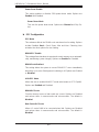
1-4 PC Health Monitoring
This section describes the PC health monitoring features of the H8DA6+/I+(-F) .
The motherboard has an onboard System Hardware Monitor chip that supports PC
health monitoring.
Onboard Voltage Monitors
The onboard voltage monitor will continuously scan crucial voltage levels. Once a
voltage becomes unstable, it will give a warning or send an error message to the
screen. Users can adjust the voltage thresholds to defi ne the sensitivity of the volt-
age monitor. Real time readings of these voltage levels are all displayed in BIOS.
Fan Status Monitor with Firmware/Software Speed Control
The PC health monitor can check the RPM status of the cooling fans. The onboard
fans are controlled by thermal management via BIOS.

Chapter 1: Introduction
1-11
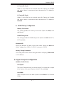
CPU Overheat/Fan Fail LED and Control
This feature is available when the user enables the CPU overheat/Fan Fail warning
function in the BIOS. This allows the user to defi ne an overheat temperature. When
this temperature is exceeded or when a fan failure occurs, the Overheat/Fan Fail
warning LED is triggered.
Auto-Switching Voltage Regulator for the CPU Core
The 5-phase-switching voltage regulator for the CPU core can support up to 80A
and auto-sense voltage IDs ranging from 0.8 V to 1.55V. This will allow the regulator
to run cooler and thus make the system more stable.
1-5 Power Confi guration Settings
This section describes the features of your motherboard that deal with power and
power settings.
Microsoft OnNow
The OnNow design initiative is a comprehensive, system-wide approach to system
and device power control. OnNow is a term for a PC that is always on but appears
to be off and responds immediately to user or other requests.
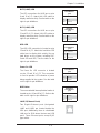
Slow Blinking LED for Suspend-State Indicator
When the CPU goes into a suspend state, the chassis power LED will start blinking
to indicate that the CPU is in suspend mode. When the user presses any key, the
CPU will wake-up and the LED will automatically stop blinking and remain on.
BIOS Support for USB Keyboard
If a USB keyboard is the only keyboard in the system, it will function like a normal
keyboard during system boot-up.

1-12
H8DA6+/I+(-F) Serverboard User’s Manual
Main Switch Override Mechanism
The power button can function as a system suspend button. When the user de-
presses the power button, the system will enter a SoftOff state. The monitor will be
suspended and the hard drive will spin down. Depressing the power button again
will cause the whole system to wake-up. During the SoftOff state, the power sup-
ply provides power to keep the required circuitry in the system alive. In case the
system malfunctions and you want to turn off the power, just depress and hold the
power button for 4 seconds. The power will turn off and no power will be provided
to the motherboard.
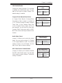
Wake-On-LAN (WOL)
Wake-On-LAN is defi ned as the ability of a management application to remotely
power up a computer that is powered off. Remote PC setup, up-dates and access
tracking can occur after hours and on weekends so that daily LAN traffi c is kept
to a minimum and users are not interrupted. The motherboard has a 3-pin header
(WOL) to connect to the 3-pin header on a Network Interface Card (NIC) that has
WOL capability. Wake-On-LAN must be enabled in BIOS.
Wake-On-Ring Header (WOR)
Wake-up events can be triggered by a device such as the external modem ringing
when the system is in the SoftOff state.
1-6 Power Supply
As with all computer products, a stable power source is necessary for proper and
reliable operation. It is even more important for processors that have high CPU
clock rates.
The H8DA6+/I+(-F) requires the use of proprietary power supplies. Please refer
to the pinout information for the power connectors in Section 6 of Chapter 2 for
detailed information on power requirements.
In areas where noisy power transmission is present, you may choose to install a
line fi lter to shield the computer from noise. It is recommended that you also install
a power surge protector to help avoid problems caused by power surges.
Warning: To prevent the possibility of explosion, do not use the wrong type of
onboard CMOS battery or install it upside down.

Chapter 1: Introduction
1-13
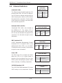
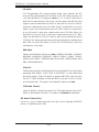
1-7 Super I/O
The disk drive adapter functions of the Super I/O Winbond
®
BMC chip includes a
fl oppy disk drive controller that is compatible with industry standard 82077/765, a
data separator, write pre-compensation circuitry, decode logic, data rate selection,
a clock generator, drive interface control logic and interrupt and DMA logic. The
wide range of functions integrated onto the Super I/O greatly reduces the number
of components required for interfacing with fl oppy disk drives.
The Super I/O provides two high-speed, 16550 compatible serial communication
ports (UARTs), one of which supports serial infrared communication. Each UART in-
cludes a 16-byte send/receive FIFO, a programmable baud rate generator, complete
modem control capability and a processor interrupt system. Both UARTs provide
legacy speed with baud rate of up to 115.2 Kbps as well as an advanced speed
with baud rates of 250 K, 500 K, or 1 Mb/s, which support higher speed modems.
The Super I/O provides functions that comply with ACPI (Advanced Confi guration
and Power Interface), which includes support of legacy and ACPI power manage-
ment through a SMI or SCI function pin. It also features auto power management
to reduce power consumption.
The IRQs, DMAs and I/O space resources of the Super I/O can be fl exibly adjusted
to meet ISA PnP requirements, which support ACPI and APM (Advanced Power
Management).

1-14
H8DA6+/I+(-F) Serverboard User’s Manual
Notes
Page is loading ...
Page is loading ...
Page is loading ...
Page is loading ...
Page is loading ...
Page is loading ...
Page is loading ...
Page is loading ...
Page is loading ...
Page is loading ...
Page is loading ...
Page is loading ...
Page is loading ...
Page is loading ...
Page is loading ...
Page is loading ...
Page is loading ...
Page is loading ...
Page is loading ...
Page is loading ...
Page is loading ...
Page is loading ...
Page is loading ...
Page is loading ...
Page is loading ...
Page is loading ...
Page is loading ...
Page is loading ...
Page is loading ...
Page is loading ...
Page is loading ...
Page is loading ...
Page is loading ...
Page is loading ...
Page is loading ...
Page is loading ...
Page is loading ...
Page is loading ...
Page is loading ...
Page is loading ...
Page is loading ...
Page is loading ...
Page is loading ...
Page is loading ...
Page is loading ...
Page is loading ...
Page is loading ...
Page is loading ...
Page is loading ...
Page is loading ...
Page is loading ...
Page is loading ...
Page is loading ...
Page is loading ...
Page is loading ...
Page is loading ...
-
 1
1
-
 2
2
-
 3
3
-
 4
4
-
 5
5
-
 6
6
-
 7
7
-
 8
8
-
 9
9
-
 10
10
-
 11
11
-
 12
12
-
 13
13
-
 14
14
-
 15
15
-
 16
16
-
 17
17
-
 18
18
-
 19
19
-
 20
20
-
 21
21
-
 22
22
-
 23
23
-
 24
24
-
 25
25
-
 26
26
-
 27
27
-
 28
28
-
 29
29
-
 30
30
-
 31
31
-
 32
32
-
 33
33
-
 34
34
-
 35
35
-
 36
36
-
 37
37
-
 38
38
-
 39
39
-
 40
40
-
 41
41
-
 42
42
-
 43
43
-
 44
44
-
 45
45
-
 46
46
-
 47
47
-
 48
48
-
 49
49
-
 50
50
-
 51
51
-
 52
52
-
 53
53
-
 54
54
-
 55
55
-
 56
56
-
 57
57
-
 58
58
-
 59
59
-
 60
60
-
 61
61
-
 62
62
-
 63
63
-
 64
64
-
 65
65
-
 66
66
-
 67
67
-
 68
68
-
 69
69
-
 70
70
-
 71
71
-
 72
72
-
 73
73
-
 74
74
-
 75
75
-
 76
76


Supermicro H8DA6+-F User manual
- Category
- Server/workstation motherboards
- Type
- User manual
- This manual is also suitable for
Ask a question and I''ll find the answer in the document
Finding information in a document is now easier with AI
Related papers
-
Supermicro H8DCL-6 User manual
-
-
SUPER MICRO Computer AS2042G72RF4 User manual
-
-
Supermicro MBD-H8SML-IF-O User manual
-
-
-
-
Supermicro H8QIi+-F User manual
-
Other documents
-
-
Gigabyte GA-7A8DRH User manual
-
Compal NBLB2 User manual
-
Belkin USB 2.0 AND FIREWIRE 6-PORT PCI CARD Owner's manual
-
Gigabyte GA-3CESL3-RH User manual
-
-
Biostar P4 TDG Engineering Validation Test Report
-
Logic Controls LC8000 User manual
-
Adaptec OnTarget™ Installation guide
-
Manhattan 702928 User manual