Page is loading ...

WTI Part No. 14533
Rev. A
RPC Series
Remote DC Power Control Switches
Products Covered:
RPC-4850 Series
RPC-40L8A4 Series
Hardware Guide

i
Warnings and Cautions:
Installation Instructions
Secure Racking
If Secure Racked units are installed in a closed or multi-unit rack assembly, they may
require further evaluation by Certification Agencies. The following items must be
considered.
1. The ambient within the rack may be greater than room ambient. Installation
should be such that the amount of air flow required for safe operation is not
compromised. The maximum temperature for the equipment in this environment is
60°C. Consideration should be given to the maximum rated ambient.
2. Installation should be such that a hazardous stability condition is not achieved due
to uneven loading.
Input Supply
Check nameplate ratings to assure there is no overloading of supply circuits that could
have an effect on overcurrent protection and supply wiring.
Grounding
Reliable earthing of this equipment must be maintained. Particular attention should
be given to supply connections when connecting to power strips, rather than direct
connections to the branch circuit.
No Serviceable Parts Inside; Authorized Service Personnel Only
Do not attempt to repair or service this device yourself. Internal components must be
serviced by authorized personnel only.
• ShockHazard-DoNotEnter
• LithiumBattery
CAUTION:Dangerofexplosionifbatteryisincorrectlyreplaced.Replace
onlywithsameorequivalenttyperecommendedbythemanufacturer.
Discardusedbatteriesaccordingtothemanufacturer'sinstructions.
Disconnect Power
If any of the following events are noted, immediately disconnect the unit from the power
source and contact qualified service personnel:
1. If the power wire becomes frayed or damaged.
2. If liquid has been spilled into the device or if the device has been exposed to rain
or water.
Two Power Supplies
Note that RPC series units feature two separate power circuits and a separate power
supply cable for each power inlet. Make certain to disconnect all power supply cables
from their power source before attempting to service or remove the unit.

iii
Table of Contents
1. Introduction. . . . . . . . . . . . . . . . . . . . . . . . . . . . . . . . . . . . . . . . . . . . . . . . . . . . . . . . . . . . . 1-1
2. UnitDescription. . . . . . . . . . . . . . . . . . . . . . . . . . . . . . . . . . . . . . . . . . . . . . . . . . . . . . . . . . 2-1
2.1. Front Panel Components - RPC-4850 Series . . . . . . . . . . . . . . . . . . . . . . . . . . . . . . . . 2-1
2.2. Back Panel Components - RPC-4850 Series . . . . . . . . . . . . . . . . . . . . . . . . . . . . . . . . . 2-2
2.3. Front Panel Components - RPC-40L8A4 Series . . . . . . . . . . . . . . . . . . . . . . . . . . . . . . 2-3
2.4. Back Panel Components - RPC-40L8A4 Series . . . . . . . . . . . . . . . . . . . . . . . . . . . . . . 2-4
2.5. Additional Button Functions . . . . . . . . . . . . . . . . . . . . . . . . . . . . . . . . . . . . . . . . . . . . . . 2-5
3. GettingStarted . . . . . . . . . . . . . . . . . . . . . . . . . . . . . . . . . . . . . . . . . . . . . . . . . . . . . . . . . . 3-1
3.1. Apply Power to the RPC Unit . . . . . . . . . . . . . . . . . . . . . . . . . . . . . . . . . . . . . . . . . . . . . 3-1
3.1.1. Connecting RPC-4850 Series Units to Power . . . . . . . . . . . . . . . . . . . . . . . . . . 3-1
3.1.2. Connecting RPC-40L8A4 Series Units to Power . . . . . . . . . . . . . . . . . . . . . . . 3-2
3.2. Connect your Computer to the RPC . . . . . . . . . . . . . . . . . . . . . . . . . . . . . . . . . . . . . . . 3-2
3.3. Communicating with the RPC . . . . . . . . . . . . . . . . . . . . . . . . . . . . . . . . . . . . . . . . . . . . 3-2
3.4. Controlling Power Circuits . . . . . . . . . . . . . . . . . . . . . . . . . . . . . . . . . . . . . . . . . . . . . . . 3-3
4. HardwareInstallation. . . . . . . . . . . . . . . . . . . . . . . . . . . . . . . . . . . . . . . . . . . . . . . . . . . . . 4-1
4.1. Applying Power to RPC-4850 Series Units . . . . . . . . . . . . . . . . . . . . . . . . . . . . . . . . . . 4-1
4.2. Applying Power to RPC-40L8A4 Series Units . . . . . . . . . . . . . . . . . . . . . . . . . . . . . . . . 4-3
4.3. Connecting Switched Devices to RPC-4850 Series Units . . . . . . . . . . . . . . . . . . . . . . . 4-5
4.4. Connecting Switched Devices to RPC-40L8A4 Series Units . . . . . . . . . . . . . . . . . . . . . 4-5
4.4.1. Output Terminal Fuses . . . . . . . . . . . . . . . . . . . . . . . . . . . . . . . . . . . . . . . . . . . 4-6
4.5. Connecting to the Alarm Inputs (RPC-40L8A4 Units Only) . . . . . . . . . . . . . . . . . . . . . . 4-7
4.6. Serial Console / RS232 Port Connection . . . . . . . . . . . . . . . . . . . . . . . . . . . . . . . . . . . . 4-8
4.6.1. Connecting a Local Computer . . . . . . . . . . . . . . . . . . . . . . . . . . . . . . . . . . . . . 4-8
4.6.2. Connecting an External Modem . . . . . . . . . . . . . . . . . . . . . . . . . . . . . . . . . . . . 4-8
4.7. Connecting the Network Cable . . . . . . . . . . . . . . . . . . . . . . . . . . . . . . . . . . . . . . . . . . . 4-8
4.8. Emergency Shut Off Function . . . . . . . . . . . . . . . . . . . . . . . . . . . . . . . . . . . . . . . . . . . . 4-9
Appendices:
A. Specifications. . . . . . . . . . . . . . . . . . . . . . . . . . . . . . . . . . . . . . . . . . . . . . . . . . . . . . . . . Apx-1
B. SerialInterfaceDescription. . . . . . . . . . . . . . . . . . . . . . . . . . . . . . . . . . . . . . . . . . . . . . Apx-2
B.1. Serial Port (RS232) . . . . . . . . . . . . . . . . . . . . . . . . . . . . . . . . . . . . . . . . . . . . . . . . . . . Apx-2
C. CustomerService. . . . . . . . . . . . . . . . . . . . . . . . . . . . . . . . . . . . . . . . . . . . . . . . . . . . . . Apx-3

1-1
1. Introduction
This Hardware Guide covers set-up and installation for our RPC Series Network Power
Switches. RPC Series units are designed to simplify the process of remotely managing
vital network elements located at distant network equipment sites and off-site facilities
by providing secure remote access to DC power switching and reboot functions at the
remote network equipment site.
Note: For instructions regarding configuration and operation of the RPC Series
Device, please refer to the WTI Firmware Guide.
Model Numbers Covered
This Hardware Guide discusses all WTI RPC Series products. Throughout this
Hardware Guide, all of these units are referred to as the "RPC."

2-1
2. Unit Description
2.1. Front Panel Components - RPC-4850 Series
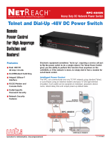
As shown in Figure 2.1, the RPC-4850 Series Front Panel includes the following:
1. CircuitStatusIndicators: A series of eight LED indicators, which light when power
to the corresponding circuit is Switched On.
2. RDYIndicator: Flashes when the RPC is ready to receive commands.
3. ONIndicator: Lights when power is applied to the Control Section.
RPC-4850
www.wti.com
Remote Power Controller
CONTROL
RDY
ON
CIRCUITS
1 2 3 4 5 6 7 8
1 2 3
Figure 2.1: Front Panel (Model RPC-4850-48V Shown)

2-2
Unit Description
2.2. Back Panel Components - RPC-4850 Series
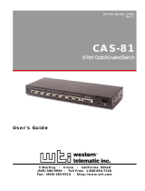
As shown in Figure 2.2, the RPC-4850 Series back panel includes the following:
1. GroundScrew
2. DefaultButton: Toggles circuits On/Off or resets unit to factory default parameters
as described in Section 2.5.
3. ResetButton: Reboots and/or resets the RPC to factory defaults as described in
Section 2.5.
4. NetworkPort: An RJ45 Ethernet port for connection to your 10/100/1000Base-T,
TCP/IP network. Note that the Network Port also includes two, small LED indicators
for Link and Data Activity. For information on Network Port configuration, please
refer to the WTI Firmware Guide.
5. ConsolePort: A DB9, RS232 serial port (DTE), for connection to a local terminal or
external modem, as described in Section 4.6.
6. RDYIndicator: (Ready) Flashes to indicate that unit is ready to receive commands.
7. SwitchedOutputCircuits: A series of eight DC, 15 Amp circuits divided into two
terminal blocks.
A. 15AmpCircuitBreakers: Each circuit includes a 15 Amp breaker.
B. StatusIndicators: Each circuit includes a Status Indicator, which lights when
the circuit is switched On.
C. MountingScrewReceptacles: Each terminal block includes two mounting
screw receptacles, which are used to install the protective cover (not shown.)
8. PowerInput: Two DC input Buses.
• RPC-4850-48VUnits:-48VDC
• RPC-4850-24VUnits:+24VDC
D. 50AmpCircuitBreakers: Each power input bus includes a 50 Amp breaker.
E. MountingScrewReceptacles: The power input terminal block includes two
mounting screw receptacles, which are used to install the protective cover
(not shown).
50 50
15 15 15 15 15 15 15 15
DEF
ACT LINK
RST CONSOLE
10/100BaseT
RDY CKT
1
CKT
2
CKT
3
CKT
4
CKT
5
CKT
6
CKT
7
CKT
8
1 2 3 4 5 6 7 8
BUS A BUS B
Ø -48 Ø Ø Ø Ø Ø Ø Ø -48 -48 -48 -48 -48 -48 -48
-48 -48 Ø Ø
1
2
3
4 5 6
7 8
D
E
A
B
C
Figure 2.2: Back Panel (Model RPC-4850-48V Shown)

2-3
Unit Description
2.3. Front Panel Components - RPC-40L8A4 Series
As shown in Figure 2.3, the RPC-40L8A4 Series Front Panel includes the following:
1. NetworkPort: An RJ45 Ethernet port for connection to your 10/100Base-T, TCP/
IP network. Note that the Network Port also includes two, small LED indicators for
Link and Data Activity. For more information on Network Port configuration, please
refer to the WTI Firmware Guide.
2. ConsolePort: A DB9, RS232 serial port (DTE), for connection to a local terminal or
external modem, as described in Section 4.6.
3. ONIndicator: Lights when power is applied to the Control Section.
4. RDYIndicator: Flashes when the RPC is ready to receive commands.
5. DefaultButton: Toggles circuits On/Off or resets unit to factory default parameters
as described in Section 2.5.
6. ResetButton: Reboots and/or resets the RPC to factory defaults as described in
Section 2.5.
7. CircuitStatusIndicators: A series of eight LED indicators, which light when power
to the corresponding circuit is Switched On.
8. AlarmInputIndicators: A series of four LED indicators which light when the
corresponding Alarm Input has generated an alarm. For more information on Alarm
Input functions, please refer to Section 4.5 and the WTI Firmware Guide.
ALARM INPUT
DEFAULT
RESET
ON
RDY
OUTPUT STATUS
1 2 3 4
A1 A2 A3 A4 B1 B2 B3 B4
www.wti.com
RPC
Remote Power Controller
Ethernet 10/100 PHONE
ACT LINK
1
2
3
4 5 6 7
8
Figure 2.3: Front Panel (Model RPC-40L8A4 Shown)

2-4
Unit Description
2.4. Back Panel Components - RPC-40L8A4 Series
As shown in Figure 2.4, the RPC-40L8A4 Series Back Panel includes the following:
1. PowerInput: Two 40 Amp DC input Buses that share a common chassis ground
line. The power input terminal block also includes two mounting brackets, which
are used to hold the protective cover (not shown).
2. SwitchedOutputCircuits-BusA: Four ten amp DC circuits in a Euro Style
output terminal fed by power input bus A. DC output voltages for RPC-40L8A4
series units are as follows:
• RPC-40L8A4-48=±48VDC,10Amps
• RPC-40L8A4-24=+24VDC,10Amps
• RPC-40L8A4-12=+12VDC,10Amps
3. OutputCircuitFuses-BusA: Four ten amp DC GMT fuses that protect the
circuits on Output Bus A. Ships with 10 Amp fuses; for custom fuses, please
contact WTI.
4. SwitchedOutputCircuits-BusB: Four ten amp DC circuits in a Euro Style
outputterminalfedbypowerinputbusB.VoltagesforeachRPC-40L8A4model
are described under item 2 above.
5. OutputCircuitFuses-BusB: Four ten amp DC GMT fuses that protect the
circuits on Output Bus B. Ships with 10 Amp fuses; for custom fuses, please
contact WTI.
6. OptionalGroundingLugLocation: Mounting holes for optional grounding lug for
6 gauge ground wire. For more information, please contact WTI.
7. AlarmInputs: Four Euro style alarm inputs, which are designed for connection to
door open alarms or other dry contacts. Each alarm input supplies 0.4 Amps of
positiveDCcurrentatthesamevoltagethatisusedtopowertheunit(e.g.,±48V
DCunitsprovide+48VDC,+24VDCunitsprovide+24VDCand+12VDCunits
provide+12VDC.)Formoreinformation,pleaserefertoSection 4.5.
1
2
3
4 6
5
7
Figure 2.4: Back Panel (Model RPC-40L8A4 Shown)

2-5
Unit Description
2.5. Additional Button Functions
The Default and Reset buttons on the RPC front panel can be used to perform the
functions described below:
Notes:
• AllFrontPanelButtonfunctionscanalsobedisabledviatheSystem
Parametersmenu,asdescribedintheWTI Firmware Guide.
• WhentheRPCisresettofactorydefaults,alluser-definedconfiguration
parameterswillbecleared,andthedefault“super”useraccountwillalso
berestored.
1. RebootOperatingSystem:
a) Press and hold the Reset button for five seconds, and then release it.
b) The RPC will reboot it's operating system; all circuits will be left in their current
On/Off state.
2. SetParameterstoFactoryDefaults:
a) Simultaneously press both the Default button and the Reset button, hold them
for five seconds, and then release them.
b) All RPC parameters will be reset to their original factory default settings, and
the unit will then reboot. All circuits will be left in their current On/Off state.
3. Toggle/DefaultAllCircuits:
a) Press the Default button, hold it for five seconds, and then release the Default
Button.
b) The RPC will switch all circuits to the Off state. If all circuits are already in the
Off state, then the unit will reset all circuits to their user defined default states.

3-1
3. Getting Started
This section describes a simplified bench test procedure for the RPC, which will allow
you to communicate with the unit in order to demonstrate basic features and check for
proper operation.
Notes:
• ThereareseparateHardwareInstallationproceduresforRPC-4850series
unitsandRPC-40L8A4seriesunits.RPC-4850seriesunitsarediscussedin
Section4.1andRPC-40L8A4seriesunitsarediscussedinSection4.2.
• FormoreinformationregardinginstallingtheRPChardwareinaworking
networkenvironment,pleaserefertoSection4.
• Forinstructionsregardingconfigurationsoptionsandadvancedoperating
features, please refer to the WTI Firmware Guide.
3.1. Apply Power to the RPC Unit
3.1.1. Connecting RPC-4850 Series Units to Power
Refer to power rating nameplate on the back panel, and then connect the RPC-4850
series unit to an appropriate power source
The RPC-4850 features two separate DC inputs; connect power wires to the unit's
Circuit "A" and/or Circuit "B" terminal blocks, then connect the wires to an appropriate
power supply. The ON LED should light, and the RDY LED should begin to flash. This
indicates that the RPC-4850 is ready to receive commands.
Notes:
• FormoreinformationregardingconnectingpowertoRPC-4850SeriesUnits,
please refer to Section4.1.
• Forthepurposeofthisbenchtestprocedure,itisnotnecessarytoconnect
powertobothinputcircuits;eithercircuitwillsupplypowerforoperationand
controlfunctions.However,whenpowerisconnectedtobothcircuits,this
allowsthesecondcircuittofunctionasaback-upintheeventofapower
outage.
• Eachindividualoutputcircuitwillsupportupto15Ampsmaximum.Thetotal
foralleightcircuitscannotexceed50Amps.
Warning: An exposed wire lead from a DC input power source can
conduct harmful levels of electricity. Make certain that no exposed portion
of the DC input wire extends from the terminal block.

3-2
Getting Started
3.1.2. Connecting RPC-40L8A4 Series Units to Power
Refer to power rating nameplate on the back panel, and then remove the protective
cover from the terminal block and connect the RPC-40L8A4 unit to an appropriate
power source.
Notes:
• FormoreinformationregardingconnectingpowertoRPC-40L8A4Series
Units,pleaserefertoSection4.2.
• RPC-40L8A4seriesunitsfeaturetwocompletelyindependentbuses,and
foreachcircuit,voltageisconnectedtothe+/-terminal(fornegative48or
positive48voltunits,powerisconnectedtothe+/-terminalsandforpositive
24and12voltunits,positivepowerisalsoconnectedtothe+/-terminals.)
Warning: An exposed wire lead from a DC input power source can
conduct harmful levels of electricity. Make certain that no exposed portion
of the DC input wire extends from the terminal block.
3.2. Connect your Computer to the RPC
In the default state, communication with the RPC via Telnet, HTTP and HTTPS are
disabled. Although communication via Telnet, HTTP and/or HTTPS can be enabled as
described in the WTI Firmware Guide, during this bench test procedure, the RPC will be
controlled via the Command Line Interface (CLI) using a local PC, connected to either
the Serial SetUp Port or Network Port:
• SerialSetUpPort: Use the Ethernet Cable and Adapter supplied with the RPC. In
the default state, the Serial SetUp Port is configured for 9600 bps.
• NetworkPort: Use the Ethernet Cable supplied with the unit. The default IPv4
address for the Network Port is 192.168.168.168.
3.3. Communicating with the RPC
Notes:
• Defaultserialportparametersaresetasfollows:9600bps,RTS/CTS
Handshaking,8DataBits,OneStopBit,NoParity.Althoughthese
parameterscanbeeasilyredefined,forthisbenchtestprocedure,itis
recommendedtoconfigureyourcommunicationsprogramtoacceptthe
default parameters.
• TheRPCfeaturesadefaultIPAddress(192.168.168.168)andadefault
SubnetMask(255.255.255.0.)ThisallowsnetworkIPv4accesstothe
CommandLineInterface,providingthatyouarecontactingtheRPCfroma
nodeonthesamesubnet.
1. AccesstheUserInterface:Start your communications program, (e.g., Tera Term,
PuTTy, etc.,) then press [Enter].
2. Username/PasswordPrompt: A message will be displayed, which prompts you
to enter your username (Login) and password. The default username is "super"
(all lower case, no quotes), and the default password is also "super". If a valid
username and password are entered, the RPC will display either the Port Status
Screen (CLI) or Main Menu (Web Browser Interface.)

3-3
Getting Started
3.4. Controlling Power Circuits
If you wish to verify that the RPC is operating properly before deploying the unit in a
working network environment, proceed as follows to connect ports and switch circuits:
1. ReviewtheHelpMenu: At the Text Interface command prompt, type /H and press
[Enter] to display the Help Menu.
2. ControllingPowerCircuits: You may wish to perform the following tests in order
to make certain that the switched circuits are functioning properly.
a) RebootCircuit: At the command prompt, type /BOOT 1 and press [Enter].
The status indicator for Circuit 1 should go Off, pause for a moment and then
go back On, indicating that the boot cycle has been successfully completed.
b) SwitchCircuitOff: At the command prompt, type /OFF 1 and then press
[Enter]. The status indicator for Circuit 1 should go Off, indicating that the
command has been successfully completed. Leave Circuit 1 in the "Off" state,
and then proceed to the next step.
c) SwitchCircuitOn: At the command prompt, type /ON 1 and press [Enter].
The status indicator for Circuit 1 should then go back On, indicating that the
command has been successfully completed.
3. ExitfromUserInterface: To exit the user interface, type /X and press [Enter].
This completes the Quick Start Guide for the RPC. Prior to placing the unit into
operation, it is recommended to refer to the remainder of this User’s Guide for important
information regarding advanced configuration capabilities and more detailed operation
instructions. If you have further questions regarding the RPC unit, please contact WTI
Customer Support as described in Appendix C.

4-1
4. Hardware Installation
4.1. Applying Power to RPC-4850 Series Units
Note:ThisprocedurediffersforRPC-40L8A4seriesunits.Forinstructionson
connectingpowertoRPC-40L8A4seriesunits,pleaserefertoSection4.2.
Refer to power rating nameplate on the back panel, and then connect the RPC-4850
series unit to an appropriate power source as shown in Figure 4.1.
RPC-4850 series units features two separate DC inputs; connect power cables to
the unit's Circuit "A" and/or Circuit "B" terminal blocks, then connect the cables to an
appropriate power supply. Note that it is not necessary to connect power to both input
circuits; either circuit will supply power for operation and control functions. However,
when power is connected to both circuits, this allows the second circuit to function as a
back-up in the event of a power outage.
Note that each individual output circuit will support up to 15 Amps maximum, and that
the total for all eight circuits cannot exceed 50 Amps.
CAUTIONS:
• Before attempting to install this unit, please review the warnings and
cautions listed at the front of the user's guide.
• This device should only be operated with the type of power source
indicated on the instrument nameplate. If you are not sure of the type of
power service available, please contact your local power company.
• Reliable earthing (grounding) of this unit must be maintained. Particular
attention should be given to supply connections when connecting to
power strips, rather than directly to the branch circuit.
Warning: An exposed wire lead from a DC input power source can
conduct harmful levels of electricity. Make certain that no exposed portion
of the DC input wire extends from the terminal block.
Input voltages for RPC-4850 units are described in the table below:
Model Number Voltage
RPC-4850-48V -48VDC
RPC-4859-24V +24VDC
When you have finished connecting power lines to the RPC-4850 unit, make certain to
replace the protective input terminal block cover.

4-2
Hardware Installation
INPUT A
INPUT B
50A
50A
(CIRCUIT
BREAKER)
15A
15A
OUTPUT
CKT 1
OUTPUT
CKT 2
-48 VDC
-48 VDC
-48 VDC
-48 VDC
0 VDC
0 VDC
0 VDC
0 VDC
B BUS
A BUS
(-48 VDC)
CIRCUITS
3 - 8
Figure 4.1: Model RPC-4850 Series Block Diagram (Model RPC-4850-48V Shown)

4-3
Hardware Installation
4.2. Applying Power to RPC-40L8A4 Series Units
Note:ThisprocedurediffersforRPC-4850seriesunits.Forinstructionson
connectingpowertoRPC-4850seriesunits,pleaserefertoSection4.1.
Refer to power rating nameplate on the back panel, and then remove the protective
cover from the terminal block and connect the RPC-40L8A4 unit to an appropriate
power source as shown in Figure 4.2 and Figure 4.3.
CAUTIONS:
• Before attempting to install this unit, please review the warnings and
cautions listed at the front of the user's guide.
• This device should only be operated with the type of power source
indicated on the instrument nameplate. If you are not sure of the type of
power service available, please contact your local power company.
• Reliable earthing (grounding) of this unit must be maintained. Particular
attention should be given to supply connections when connecting to
power strips, rather than directly to the branch circuit.
Warning: An exposed wire lead from a DC input power source can
conduct harmful levels of electricity. Make certain that no exposed portion
of the DC input wire extends from the terminal block.
Note:RPC-40L8A4seriesunitsfeaturetwocompletelyindependentbuses,
andforeachcircuit,voltageisconnectedtothe+/-terminal(fornegative48or
positive48voltunits,powerisconnectedtothe+/-terminalsandforpositive
24and12voltunits,positivepowerisalsoconnectedtothe+/-terminals.)
Input voltages for RPC-40L8A4 units are described in the table below:
Model Number Voltage Voltage Range
RPC-40L8A4-48 +48or-48VDC 18to72VDC
RPC-40L8A4-24 +24VDC 18to72VDC
RPC-40L8A4-12 +12VDC 9to36VDC
When you have finished connecting power lines to the RPC-40L8A4 unit, make certain
to replace the protective input terminal block cover.
A ±DC
(Branch A Voltage:
Connect ±48, +24
or +12 V DC)
A RTN
(Branch A Return)
Chassis
Ground
B ±DC
(Branch B Voltage:
Connect ±48, +24
or +12 V DC)
B RTN
(Branch B Return)
DC Power Wire
10 to 12 Gauge
Use No. 10
Ring Terminal
Figure 4.2: DC Input Block Terminal (RPC-40L8A4 Series - Protective Cover Not Shown)

4-4
Hardware Installation
INPUT A
INPUT B
10A
10A
OUTPUT
CKT A1
OUTPUT
CKT A4
±48 VDC
±48 VDC
±48 VDC
±48 VDC
0 VDC
0 VDC
0 VDC
0 VDC
10A
OUTPUT
CKT B1
±48 VDC
0 VDC
10A
OUTPUT
CKT B4
±48 VDC
0 VDC
Figure 4.3: RPC-40L8A4 Series Units; Block Diagram

4-5
Hardware Installation
4.3. Connecting Switched Devices to RPC-4850 Series Units
Note:ThisprocedurediffersforRPC-40L8A4seriesunits.Forinstructions
onconnectingswitcheddevicestoRPC-40L8A4seriesunits,pleasereferto
Section4.4.
Make certain that the power supply to the RPC-4850 series unit is switched Off, and
then connect the supply cables from your DC powered devices to the Switched Output
Circuits on the RPC-4850 back panel. Check to make certain that cables are securely
attached, and then install the protective covers over each output terminal block. The
protective covers are held in place by screws that pass through the holes in the cover
and then thread into the screw receptacles at the end of each Output Terminal Block.
4.4. Connecting Switched Devices to RPC-40L8A4 Series Units
Note:ThisprocedurediffersforRPC-4850seriesunits.Forinstructionson
connectingswitcheddevicestoRPC-4850seriesunits,pleasereferto
Section4.3.
The output terminals on the RPC-40L8A4 back panel are used to connect DC voltage to
each switched device. Each output terminal includes eight connectors (four circuits.)
To connect wires to the DC output terminal block, refer to Figure 4.4 below and proceed
as follows:
Notes:
• Eachindividualoutputcircuitwillsupportupto10Ampsmaximum;thetotal
forallfourcircuitsoneitherbuscannotexceed40Amps.
• Whentighteningorlooseningtheterminalblockretainingscrews,usea
screwdriverwitha3mmwideblade.
Warning: An exposed wire lead from a DC input power source can
conduct harmful levels of electricity. Make certain that no exposed portion
of the DC input wire extends from the terminal block.
± V
(Circuit A1 Voltage:
+48, -48, +24 or
+12 V DC Out)
R
(Circuit A1 Return)
A1 A2
A3 A4
Wire Holes
Retaining Screws
DC Power Wires:
14 to 24 Gauge
Strip 0.5 Inch
(11 to 13 mm)
Figure 4.4: DC Output Terminal Blocks (RPC-40L8A4 Series - Fuses Not Shown)

4-6
Hardware Installation
Clear Cap
Red Dot
Blown
Fuse
Good
Fuse
Figure 4.5: DC Output Terminal Block Fuses (RPC-40L8A4 Series Units Only)
1. Prior to inserting a wire into the the DC terminal block, you must use loosen the
retaining screw in order to allow the wire to enter the wire hole. Use a screwdriver
with a 3mm wide blade to turn the retaining screw all the way to the left
(counter-clockwise.)
2. Firmly insert the wire into the wire hole and push the wire into the hole until
resistance is felt.
3. While holding the wire in place, use a screwdriver with a 3mm wide blade to tighten
the retaining screw. The screwdriver that is used to tighten the retaining screw must
be narrow enough to reach the retaining screw unobstructed. Note that in order to
properly secure the wire, you must push down on the screwdriver while tightening
the retaining screw until the screw is firmly seated.
Note:Ifyouhavedifficultysecuringthewiretotheterminalblock,make
certainthatyouareusingascrewdriverwitha3mmwideblade(ornarrower,)
and that the retaining screw and is tight enough to hold the wire in place.
Caution: Do not over tighten the retaining screws. The recommended
maximum torque is 4.5 lbf-in (72 ozf-in.)
4. Tug on the wire to make certain that the wire is firmly held in place.
4.4.1. Output Terminal Fuses
Note that each output terminal includes four fuses; one for each circuit on the output
terminal. If a fuse is blown, a red dot will appear in the clear cap as shown in Figure 4.5.
To remove a fuse, use a pair of pliers to grasp the black body of the fuse, and then
gently pull the fuse loose from the RPC-40L8A4 unit. The RPC-40L8A4 ships with 10
Amp fuses; for custom fuses, please contact WTI.

4-7
Hardware Installation
4.5. Connecting to the Alarm Inputs (RPC-40L8A4 Units Only)
The RPC-40L8A4 back panel includes four alarm inputs, designed for connection to
dooropenalarmsorotherdrycontactalarms.Each+pinsuppliespositiveDCvoltage
atthesamevoltagethatisusedtopowertheunit(i.e.,±48VDCunitsprovide+48V
DC,+24VDCunitsprovide+24VDCand+12VDCunitsprovide+12VDC.)
Note that when the RPC-40L8A4 unit is shipped from the factory, the removable alarm
input connectors are enclosed in separate plastic bag, included in the shipping box and
must be installed by the user.
When connecting wires to alarm inputs, make certain each wire is properly seated and
firmly held in place by the retaining screw. As shown in Figure 4.6, in order to properly
seat the wire the retaining screw must be turned counter-clockwise until the metal "gate"
in the wire hole is open. If the metal gate is closed, the wire will not seat properly. After
inserting the wires, tighten both screws to secure the wires to the connector and snap
the connector in place on the back panel of the RPC-40L8A4 unit.
Caution: Do not over tighten the retaining screws. The recommended
maximum torque is 4.5 lbf-in (72 ozf-in.)
Note:ForinstructionsregardingconfigurationoftheAlarmInputAlarm,please
refer to the WTI Firmware Guide.
Input CurrentOutput Current:
+48, +24 or
+12 V DC
+ -
Retaining
Screws
Wire
Holes
Gate Open
Gate Closed
Alarm Wire
14 to 24 Gauge
Strip 0.25 Inch
(6.35 mm)
Figure 4.6: Connecting to the Alarm Inputs (RPC-40L8A4 Series Units Only)

4-8
Hardware Installation
4.6. Serial Console / RS232 Port Connection
The Serial Console Port can be connected to either an external modem or a local PC,
but not both items at the same time. In the default state, the Console port is configured
for 9600 bps, no parity, 8 data bits, 1 stop bit. Appendix B describes the Console Port
interface. Note that RPC-4850 series units differ from RPC-40L8A4 series units as
follows:
• RPC-4850SeriesUnits: The RPC-4850 SetUp Port is a male, RS232C DB9
connector.
• RPC-40L8A4SeriesUnits: The RPC-40L8A4 SetUp Port is a female RS232C
RJ45 connector.
4.6.1. Connecting a Local Computer
Use the supplied null modem cable to connect your computer console port to the
RPC SetUp (RS232) Port. Make certain that the Serial Port Mode is set to "Normal" (the
default setting) as described in the WTI Firmware Guide.
4.6.2. Connecting an External Modem
When connecting directly to an external modem, use a standard AT to Modem cable.
Make certain that the modem is initialized at the same default parameters as the RPC
Console Port. Make certain that the RPC Serial Port Mode is set to "Modem" or "Modem
PPP" as described in The WTI Firmware Guide.
4.7. Connecting the Network Cable
The Network Port is an RJ45 Ethernet jack, for connection to a TCP/IP network. Connect
your Ethernet cable to the Network Port. Note that the RPC includes a default IP
address (192.168.168.168) and a default subnet mask (255.255.255.0.) When installing
the RPC in a working network environment, it is recommended to define network
parameters as described in the WTI Firmware Guide.
Note:TheRPCfeaturesa10/100/1000Base-Tauto-negotiatingInterface;
speedandduplexmodewillbeautomaticallynegotiated.Whenconnectingto
anEthernetinterface,mostrouterswitcheswillautosensetodetermineifthe
deviceis1000Base-T,100Base-Tor10Base-T,andthenconfigurethenetwork
interfaceaccordingly.Ifyourrouterswitchdoesnotautosense,theRPCwill
autonegotiatespeedandduplexmode.
/