Page is loading ...

1
( ) 044.pdf
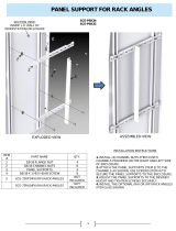
Center Panel Support Installation
Installation Instructions
Item # Part Name QTY.
1 Left Support 1
2 Right Support 1
3 Top/Bottom Angle Support 1
102027 Bolt Pack
Contains items 4-6
1
4 3/8-16 X 3/4 Serrated Flanged Bolt 9
5 3/8-16 X 3/4 Serrated Flanged Nut 5
6 3/8-16 Channel Nut 4
Part Numbers
SCE-60FSCPS
SCE-72FSCPS
SCE-90FSCPS
Step 1: Attach right support (Item 2) to left
support (Item 1) as shown. Attach three bolts
(Item 4) to installed pem nuts.
Step 2: Attach top and bottom support (Item 3)
to top of support assembly as shown. Fasten with
a bolt (Item 4) and a nut (Item 5).
Step 3: Install 4 channel nuts (Item 6) in the
channel provided in the top and bottom of a
2-Door or 2-Door Duel Access Enclosure.
Step 4: Position center panel support assembly
between top and bottom mounting channels
in the enclosure. Attach center panel support
assembly to mounting channels as shown with
4 bolts (Item 4). Loosen bolt (Item 4) to adjust
length of center panel support if required.
Step 5: Install full or half panel, swing-out panel,
or relay rack angles on the left side of center
panel support. Slotted holes are provided in top
support (Item 3) and bottom of left support
(Item 1) to provide adjustment if required.
Step 6: Install full or half panel, swing-out panel,
or relay rack angles on right side of center panel
support. Slotted holes are provided in right
support (Item 2) to adjust width of enter panel
support if required.
1
2
3
4
5
6
3/8-16
self-clench nuts
3 locations
/


