Kampmann 2-stage three-phase switch, type 30277 Installation guide
- Type
- Installation guide

Operating instructions
Please retain this manual carefully for future use!
Read prior to commissioning!
1.26
1.45
I 210/06/11/1 GB
2-Stage, Three-Phase Controller 1.96
With Timing Switch and Room Temperature Controller
Type 30277

1. Correct and proper use . . . . . . . . . . . . . . . . . . . . . . . . . . . . . . . . . . . . . . 3
2. Safety advice . . . . . . . . . . . . . . . . . . . . . . . . . . . . . . . . . . . . . . . . . . . . . . . . 4
3. Assembly and installation. . . . . . . . . . . . . . . . . . . . . . . . . . . . . . . . . . . 5
3.1 Laying the Cables . . . . . . . . . . . . . . . . . . . . . . . . . . . . . . . . . . . . . . . . . . 6
3.2 Protection . . . . . . . . . . . . . . . . . . . . . . . . . . . . . . . . . . . . . . . . . . . . . . . . . 6
3.3 Electical Connection. . . . . . . . . . . . . . . . . . . . . . . . . . . . . . . . . . . . . . . . . 7
4. Operation . . . . . . . . . . . . . . . . . . . . . . . . . . . . . . . . . . . . . . . . . . . . . . . . . . 9
4.1 Timing Switch Operation . . . . . . . . . . . . . . . . . . . . . . . . . . . . . . . . . . . 12
4.2 Connection. . . . . . . . . . . . . . . . . . . . . . . . . . . . . . . . . . . . . . . . . . . . . . . 12
4.3 Display / operating elements . . . . . . . . . . . . . . . . . . . . . . . . . . . . . . . 12
4.4 Program structure . . . . . . . . . . . . . . . . . . . . . . . . . . . . . . . . . . . . . . . . . 13
4.5 Setting the timer . . . . . . . . . . . . . . . . . . . . . . . . . . . . . . . . . . . . . . . . . 14
4.6 Setting of time format, time and day . . . . . . . . . . . . . . . . . . . . . . . . 15
4.7 Pre-set programs . . . . . . . . . . . . . . . . . . . . . . . . . . . . . . . . . . . . . . . . . 16
4.8 User defined programs . . . . . . . . . . . . . . . . . . . . . . . . . . . . . . . . . . . . 17
4.9 Deleting programs . . . . . . . . . . . . . . . . . . . . . . . . . . . . . . . . . . . . . . . . . 19
4.10 Summer/winter changeover . . . . . . . . . . . . . . . . . . . . . . . . . . . . . . . 19
4.11 Automatic mode/Continuous mode . . . . . . . . . . . . . . . . . . . . . . . . . 19
4.12 Technical data on timer . . . . . . . . . . . . . . . . . . . . . . . . . . . . . . . . . . . 20
5. Start-Up . . . . . . . . . . . . . . . . . . . . . . . . . . . . . . . . . . . . . . . . . . . . . . . . . . . 21
6. Technical Data . . . . . . . . . . . . . . . . . . . . . . . . . . . . . . . . . . . . . . . . . . . . . 23
Printed on environmentally friendly, chlorine-free paper; all rights reserved; reprints, even excerpts, may not be used without our permission; subject to change
.1.96 2-Stage, Three-Phase Controller
With Timing Switch and Room Temperature Controller, Type 30277
Operating instructions
.1.96 2-Stage, Three-Phase Controller
With Timing Switch and Room Temperature Controller, Type 30277
Operating instructions
Symbols:
Important!
Danger!
Non-observance of this
information may cause
serious damage to
persons or property.
Danger of
electrocution!
Non-observance of this
information may cause
serious damage to
persons or property by
electric current.
Read this manual
through carefully
before commencement
of installation!
All persons involved
in the installation,
commissioning and
use of this product are
duty bound to pass this
manual onto subsequent
tradespersons and then
to the end user or
operator. Retain this
manual until the
system is ultimately
decommissioned!
Amendments to the
content of this manual
may take place without
prior notice being
given!

3
2-Stage, Three-Phase Controller 1.96
With Timing Switch and Room Temperature Controller, Type 30277
Operating instructions
2-Stage, Three-Phase Controller 1.96
With Timing Switch and Room Temperature Controller, Type 30277
Operating instructions
1. Correct and proper use
Kampmann 2-stage controller Type 30277 has been built according to the
latest state of the art and the recognised safety regulations. Nonetheless,
its use may be hazardous to persons, or may have an adverse effect on the
device or other material, if the units are not installed and put to operation
in an expert manner or if they are employed for undesignated use..
Kampmann 2-stage controller Type 30277 is to be used exclusively for
indoor areas (e. g., industrial halls and warehouses, sales areas, exhibitions,
etc.). The unit shall not be used in wet areas, in potentially explosive areas,
in rooms with aggressive atmospheres or in the open. The products must
be protected against moisture during installation. If in doubt, their use
must firstly be agreed with the manufacturer. Any other or exceeding use
is deemed as being undesignated. The unit operator is liable for any resul-
ting damage.
The designated use also includes the adherence to the notes on
installation rendered in these instructions. The installation of this product
requires special skills in the fields of heating, cooling, ventilation and
electrical engineering. These skills are usually taught during vocational
training in the indicated professions and are not described separately here.
Any damage caused by inexpert installation must be borne by the
operator.
The following Kampmann air treatment units can be combined with stage
switch type 30277:
Kompakt series TOP, Ultra, TIP, Resistent
(type ending in the number 36 or 38)
These instructions cover the following areas:
Installation
Electrical installation
Start-up and operation
Regulations
Accident Prevention Regulations VBG, VBG4, VBG9a
DIN VDE 0100, DIN VDE 0105
EN 60730-1 (part 1)
Regulations (TABs) of the local electricity boards
As well as the generally recognised rules of technology.
Carefully read through the
instructions prior to installing
the 2-stage three-phase
controller:

2. Safety advice
This 2-stage three-phase controller has been developed and produced
with state-of-the-art technology and in accordance with the current legal
standards and regulations. Observe the contents of these instructions to
ensure that the unit is installed and works properly.
The installation of this product requires special skills in the fields of heating,
cooling, ventilation and in electrical engineering. These skills are usually
taught during vocational training in the indicated professions and are not
described separately here. Any damage caused by inexpert installation
must be borne by the operator.
On account of his professional education, the fitter of this device should,
among other things, also have sufficient knowledge of:
- the safety and accident prevention regulations
- the guidelines and the recognised rules of technology, such as VDE
directives,
- DIN and EN standards
How to work in a safety-conscious manner
GDisconnect all equipment you need to work on from the power supply!
GMake sure that this equipment cannot be turned on again by
unauthorised persons! Wait until the fan comes to a standstill!
GFor installation, only use stable lifting platforms and scaffolding!
Modifications on the device
Do not carry out any modifications, reconstructions or installation work on
the device without prior harmonisation with the manufacturer as this may
impair the safety and operation. Any alterations made to the equipment
could lead to loss of warranty! Warranty void if unit is opened.
Incorrectly connected products may become damaged! The manufacturer
will not be liable for injuries and material damage caused when the
device has been wrongly connected and/or incorrectly used!
Important! Due to the fact that the unit is switched on again
automatically after a power failure, the speed selector switch should be in
the 0 position once the power is resumed!
4
.1.96 2-Stage, Three-Phase Controller
With Timing Switch and Room Temperature Controller, Type 30277
Operating instructions
.1.96 2-Stage, Three-Phase Controller
With Timing Switch and Room Temperature Controller, Type 30277

5
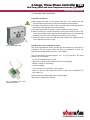
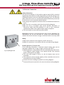
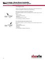
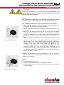
3. Assembly and installation
Controller installation
GDe-energise all parts of the system that are to be worked on and
ensure that they cannot be reconnected without authorisation!
GConsider the protection class of the controller before selecting where it
should be mounted (See the technical data)!
GThe (wall-mounted) unit must only be installed on a flat surface.
GBefore installing it, remove the plate covering the screws shown in Fig.
1 and unscrew the screws. Remove the terminal block cover. The spacing
between the drill holes is indicated on the back of the casing.
GScrew the device onto the wall and then replace the terminal block
cover. Replace the screw covers.
Installing the room temperature sensor
The room temperature sensor records the temperature at the place of
installation. For this reason, select the place of installation so that the
temperature measurement process is not hindered.
The unit should be mounted approx. 1.5 – 2 m off the floor. The units
should not be mounted:
- on poorly-insulated exterior walls,
- right next to doors and windows (because of draughts),
- behind curtains or furnishings,
- in direct sunlight,
- in the current of air emitted by the heaters,
- above or near to other external sources of heat, such as radiators, TV
sets, lamps, etc.
Please observe the permissible sensor cable length!
(See page 6: Installing the Cables)
2-Stage, Three-Phase Controller 1.96
With Timing Switch and Room Temperature Controller, Type 30277
Operating instructions
Fig. 1: Opening the unit
Fig. 2: Installing the room
temperature sensor
2-Stage, Three-Phase Controller 1.96
With Timing Switch and Room Temperature Controller, Type 30277

6
.1.96 2-Stage, Three-Phase Controller
With Timing Switch and Room Temperature Controller, Type 30277
Operating instructions
3.2 Protection
Fuses for the equipment should be provided by the customer. The
protective organs upstream must be adapted to suit the maximum
possible current provided by the controller (refer to the technical data).
The inside of the controller is equipped with 2 miniature fuses (ø 5*20 mm)
in the connection area:
F1 (on the left): primary 230V/500mA delay fuse for electronic
components.
F2 (on the right): secondary 315mA delay fuse for electronic components.
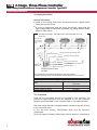
3.1 Laying the Cables
General Information
GInstall all low voltage lines (room temperature sensors, digital inputs)
taking the shortest route.
GIt must be guaranteed that the extra low-voltage cables and the
high-voltage cables are physically separated, e.g., using metallic divider
plates on cable ducts.
Maximum permissible cable lengths:
Mains Depending on the load and cable
cross-section
Air heaters (all!) max. 250 m
Room temperature sensors max. 100 m
External change-over contacts max. 200 m
All of the necessary wire numbers including earth wires must be stated.
*Shielded cables (e.g. J-Y(St)Y, 0.8 mm) should be installed separately from power lines!
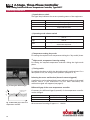
Air heater with 2 stages – three phase motors, type end numbers 36 or 38
Shown: Ultra
2-stage three-phase controller
Type 30277
.1.96 2-Stage, Three-Phase Controller
With Timing Switch and Room Temperature Controller, Type 30277
Mains 230V/ 50Hz
Only for units with
Integral condensate
pumps
Room temperature
sensor
Mains
3x400V/50Hz
Controller valve, 230 V closed without current
Additional controllers, type 30177
Controller valvel, 230 V closed
Voltage-free signal
Voltage-free signal
day/night
malfunction
Fan operation
Change–over between
heating / cooling
External contact, voltage-free

7
2-Stage, Three-Phase Controller 1.96
With Timing Switch and Room Temperature Controller, Type 30277
Operating instructions
3.3 Electrical Connection
Safety Information
The electrical installation of this product requires special skills in electrical
engineering. These skills are usually taught during vocational training in the
indicated professions and are not described separately here. The following
safety information has to be checked and observed before any work may
be carried out on the controller and the devices:
GDe-energise the equipment and ensure that no unauthorised restart can
occur.
GWire the unit in accordance with the enclosed wiring diagrams.
GWire the unit in accordance with current German Association of
Electricians (VDE) and EN guidelines as well as the connection
requirements (TAB) of the regional power supply companies.
GThe unit should only be wired using fixed cables.
Important! Incorrectly connected products may become damaged! The
manufacturer will not be held liable for injuries and material damage
caused if the device has been wrongly connected and/or incorrectly used!
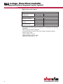
Wiring
GRemove the terminal covers (figure 3); see P.5 above too)
GMake all connections in accordance with the enclosed wiring diagram.
Parallel operation of several units
If the following information is observed several heating units can be
operated in parallel with a single 2-stage controller type 30277:
GParallel operation is only possible with units which have the same motor
circuit diagrams (types ending in the number 36/38). Their electrical
power consumptions may differ.
GThe total cable length of 250 m to the air heaters must not be
exceeded.
GThe maximum current carrying capacity of the controller must not be
exceeded (see the technical data)..
GConnect all motor windings in parallel (see wiring diagram).
GConnect all thermal contacts for all motors in series (see wiring diagram).
Fig. 3: Opening the unit
2-Stage, Three-Phase Controller 1.96
With Timing Switch and Room Temperature Controller, Type 30277

.1.96 2-Stage, Three-Phase Controller
With Timing Switch and Room Temperature Controller, Type 30277
Operating instructions
8
Digital inputs and outputs
*The voltage-free relay contact "malfunction" is activated in the following
situations:
- Motor thermal contact triggered
- Condensate alarm (only for units with integral condensate pump)
- Broken sensor cable
- Sensor cable short circuit
- Reverse polarity of sensor cable
- Measured temperature < 5°C
Digital inputs
Change-over between
heating/cooling
Heating Input DE2-GND open
Cooling Input DE2-GND closed
Digital outputs
Notification of day/night Night Output DE/A-GND closed
Day Output DE/A-GND open
Notification of ventilator
operation
Operation Output closed
No operation Output open
Malfunction warning* Malfunction Output closed
No malfunction Output open
.1.96 2-Stage, Three-Phase Controller
With Timing Switch and Room Temperature Controller, Type 30277
Operating instructions

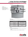
4. Operation
1
Pilot Lamp
The pilot lamp displays the current operating status of the equipment:
If the TC and sensor fault occur simultaneously, the sensor fault is
displayed.
Functions in Auto-day-heating mode
1. If the poles are reversed or the sensor cable short circuits, turn off the
stages.
2. If the sensor cable breaks or there is frost, stage 2 is turned on.
9
2-Stage, Three-Phase Controller 1.96
With Timing Switch and Room Temperature Controller, Type 30277
Operating instructions
1
Pilot lamp
2
Speed selector switch
3
Operating mode selector switch
4
Temperature adjustment, day
5
Adjustment of lowering value, night
6
Digital timing switch
1
3
4
5
6
2
Off No supply voltage
Continuously ON Power supply provided, ready for operation
Blinking signal, 0,8 sec. LED On
0,8 sec. LED Off Control active, heating mode
Blinking signal, 2 sec. LED On
2 sec. LED Off Control active, cooling mode
Blinking signal, 0,2 sec. LED On
0,2 sec. LED Off
Motor thermal contact triggered
(TC fault or condensate overflow)
Blinking signal, 0,05 sec. LED On
0,5 sec. LED Off Sensor fault
2-Stage, Three-Phase Controller 1.96
With Timing Switch and Room Temperature Controller, Type 30277
Operating instructions

10
.1.96 2-Stage, Three-Phase Controller
With Timing Switch and Room Temperature Controller, Type 30277
Operating instructions
2
Speed selector switch
The signal lamp indicates the current operating status of the equipment:
3
Operating mode selector switch
*If the speed selector switch is in the "Auto" position, the "Day" mode of operation is active..
4
Temperature setting, day mode
For setting the required room temperature during the "day mode" phase.
5
Night mode, temperature lowering setting
For setting the required temperature reduction during the night mode
phase.
6
Timing switch
For setting the times at which the day/night mode is switched over. For a
description of this, see timing switch operation (Chapter 4.1 ff)
Releasing the motor malfunction (thermal contact triggered)
A malfunction can be released via the zero reference position of the speed
selector switch. If the malfunction has not been eliminated, the
malfunction signal will reappear (see page 9).
0Equipment turned off
1Operation only in stage 1
2Operation only in stage 2
auto Automatic speed change-over regardless of the room temperature
set-point and actual value.
Day Room temperature regulated to the day temperature which has
been set
Night Room temperature regulated to the lower temperature which has
been set
Timer The integrated timer switches over between the day temperature
and the lower temperature
Man * Continuous fan operation at the set speed level
Fig. 4: Setting the differential gap
Differential gap of the room temperature controller
If necessary, the differential gap (hysteresis) of the temperature controller
can be changed:
We recommend a setting of approx. +/- 1 Kelvin.
Fig. 5: Differential gap of the room
temperature controller
Hysteresis Switching frequency Control deviation
Small High Low
Large Low Large
XRT
WRT
.1.96 2-Stage, Three-Phase Controller
With Timing Switch and Room Temperature Controller, Type 30277
Differential gap
(hysteresis)

11
2-Stage, Three-Phase Controller 1.96
With Timing Switch and Room Temperature Controller, Type 30277
Operating instructions
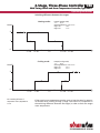
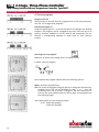
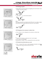
Cooling mode:
Heating mode:
If the actual room temperature remains more or less the same for approx.
10 minutes when running in stage 1, stage 2 will switch on, irrespective of
the switching difference between the stages, in order to reach the target
room temperature.
1
0
T
T
soll
-
1
/
2
SD-
1
/
4
SD +
1
/
4
SD+
1
/
2
SD
-
1
/
2
SD-
1
/
4
SD +
1
/
4
SD+
1
/
2
SD
2
1
0
T
Level
Level
T
soll
2
SD = Switching difference of
temperature control, adjustable 0.5
to 5 K
Example (Heating mode):
T actl: 20 °C
Switching difference = 4 K = ± 2 K
Stage 1 on: 18 °C
Stage 2 on: 17 °C
Example (Cooling mode):
T actl: 20 °C
Switching difference = 4 K = ± 2 K
Stage 1 on: 22 °C
Stage 2 on: 23 °C
Switching difference between the stages
2-Stage, Three-Phase Controller 1.96
With Timing Switch and Room Temperature Controller, Type 30277

12
.1.96 2-Stage, Three-Phase Controller
With Timing Switch and Room Temperature Controller, Type 30277
Operating instructions
4.1 Timing Switch Operation
Safety Information
Any defect on the timer must be repaired and tested by a qualified
engineer or can also be repaired under the supervision and guidance of a
qualified engineer.
Installation instructions:
The unit is suitable for use in ambient conditions with normal levels of
pollution in the air.
Operating instructions:
During the development of our products, we place very high demands
on the electromagnetic compatibility (EMC) of the electronic components.
The interference immunity achieved clearly exceeds the currently-valid
requirements of the corresponding EN standards. Check in each
individual case whether additional protection measures are needed, e.g.,
the integration of respective components (Varistor, suppressor diode,
RC element).
In extreme cases, it is recommended that an additional assembly group be
included, e.g., an isolating relay or switching contact, interference
suppression filter.
User instructions:
Do not use metallic pointed or sharp objects (e.g. needles) to press buttons
which are tool-operated.
4.2 Connection
see Fig. 6
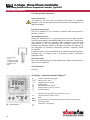
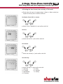
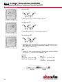
4.3 Display / operating elements (Figure 7)
Fig. 6: Connection
Fig. 7: User interface
Overview of daily switching program
Setting of 24h or am/pm
Summer/winter clock changes
Weekday display
Switching status display ON/OFF
Manual operation / fixed ON / fixed OFF
Automatic operation
Adjustment keys: By pressing the key longer than 2 sec. you
can adjust the timer in steps of 5 units.
Reset
By pressing the menu key programming is terminated and the system reverts to
automatic operation
Confirmation of programming
1 = +3.4 V (red)
2= 0 V
3 = Channel 1 output
4 =Channel 2 output
(Channel 2 is not
used)
.1.96 2-Stage, Three-Phase Controller
With Timing Switch and Room Temperature Controller, Type 30277
Operating instructions

13
2-Stage, Three-Phase Controller 1.96
With Timing Switch and Room Temperature Controller, Type 30277
Operating instructions
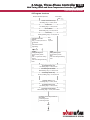
4.4 Program structure
2-Stage, Three-Phase Controller 1.96
With Timing Switch and Room Temperature Controller, Type 30277
Operating instructions
Reset (first installation adjustment) Review/adjust
Set time: Format 24h or am/pm
24h blinking, using +/- to select, then OK
Set time: Hour
Hour blinking, using +/- to select, then OK
Set time: Minute
Minute blinking, using +/- to select, then OK
Set time: Day
Monday (1) blinking, using +/- to select, then OK
Set switching ON time: Hour
Hour blinking, using +/- to select, then OK
Set switching ON time: Minute
Minutes blinking, using +/- to select, then OK
Set switching ON time: Days
Mo-Su (1-7) blinking, using +/- to select, then OK
Set display: Channel 1 or 2
Ch1 blinking, using +/- to select, then OK
Set switching OFF time: Hour
Hour blinking, using +/- to select, then OK
Set switching OFF time: Minute
Minutes blinking, using +/- to select, then OK/Menu
Note:
P01-03
are pre-set
Set Program: P01 / P02 /
P03 or P--
Using +/- to select, then OK to set
ON/OFF times
or
press Menu to terminate
programming.
P01-03, P--
Setting switching times:
First free memory location
blinks.
Press ''-'' to go back one memory
location.
Press OK for setting the switching
times.
Prog01
Setting switching times:
First free memory location
blinks.
Press OK for setting the switching
times.
A maximum of 20 memory locations can
be occupied
10 switching ON times
10 switching OFF times
Menu
RUN

14
.1.96 2-Stage, Three-Phase Controller
With Timing Switch and Room Temperature Controller, Type 30277
Operating instructions
4.5 Setting the timer
Setting of this programmable timer is depending of the user preference to
use pre-set programs or defining own programming.
Using Pre-set programs (first time installation):
The following values can be set. Settings can be made using the reset
button:
- 24h or am/pm
- Time (hour and minutes)
- Week day
- Pre-set programs P01 to P03
©For Settings see Chapters 4.6 and 4.7
User defined programming by Menu mode:
The following values can be set. Settings can be made using the menu
button:
- 24h or am/pm
- Time (hour and minutes)
- Week day
- Programs P--
©For Settings see Chapters 4.6 and 4.8
.1.96 2-Stage, Three-Phase Controller
With Timing Switch and Room Temperature Controller, Type 30277

15
2-Stage, Three-Phase Controller 1.96
With Timing Switch and Room Temperature Controller, Type 30277
Operating instructions
4.6 Setting the time format, time and day of the week
GFirstly select the type of programming i.e. Reset or Menu mode (see
chapter 4.5 above), then continue as follows:
Set display format 24h or am/pm
GSelect 24 hr or AM/PM (+/-) and confirm with OK.
Set hour
GSelect the hour (+/-) and confirm with OK.
Set minutes
GSelect the minutes (+/-) and confirm with OK.
Set week day
GSelect the day (+/-) and confirm with OK.
1 = Monday 5 = Friday
2 = Tuesday 6 = Saturday
3 = Wednesday 7 = Sunday
4 = Thursday
2-Stage, Three-Phase Controller 1.96
With Timing Switch and Room Temperature Controller, Type 30277

16
.1.96 2-Stage, Three-Phase Controller
With Timing Switch and Room Temperature Controller, Type 30277
Operating instructions
4.7 Pre-set programs
Programs P01-03
The switching on and off times for programs P01 to P03 are preset (pre).
The user can change these programs.
Individual program, P--
Under the menu option P-- you have the option of creating a user-defined
program. This program can be changed at any time. There are up to 20
memory locations available for 10 OFF and 10 ON commands. You can
allocate a corresponding weekday or week block to each memory
location.
Selecting pre-set programs:
Sequence to follow after setting time in the Reset mode.:
GSelect a pre-set program.
Once selected the program desired there are following options:
Menu: terminate programming
OK: Call up pre-set programs using OK either to change the selection (any
program ON or OFF can be modified by using ''+'' or ''-'' keys and
confirming with OK) or accept it using OK. This also allows you to
move to the next available memory field to add new programs (see
the following page).
after selecting P02 you should also program:
Sa-Su 22:30 ON (prog05)
23:00 OFF (prog06)
.1.96 2-Stage, Three-Phase Controller
With Timing Switch and Room Temperature Controller, Type 30277

17
2-Stage, Three-Phase Controller 1.96
With Timing Switch and Room Temperature Controller, Type 30277
Operating instructions
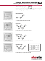
4.8 User defined programs
Sequence to follow after setting time and week day while running Menu
mode or adding programs to the pre-set P01 to P03:
Select program ON
GSet the program and confirm with OK.
Set hour ON
GSelect the hour (+/-) and confirm with OK.
Set minutes ON
GSelect the minutes (+/-) and confirm with OK.
Set week day ON
GSelect the day (+/-) and confirm with OK.
2-Stage, Three-Phase Controller 1.96
With Timing Switch and Room Temperature Controller, Type 30277
Possible week blocks and individual days

18
.1.96 2-Stage, Three-Phase Controller
With Timing Switch and Room Temperature Controller, Type 30277
Operating instructions
Set hour OFF
GSelect the hour (+/-) and confirm with OK.
Set minutes OFF
GSelect the minutes (+/-) and confirm with OK.
Set week day OFF
GShould the OFF command be the same day of ON command then
select Menu to terminate programming or select OK to go to a
new program ON setting.
Shift
GShould the OFF command be the following day of ON command
then select ''+'' key then select Menu or OK.
Example:
Mo - Fr Mo - Fr
20:00 p.m. - 03:00 a.m. ON ©20:00 p.m. - 03:00 a.m. ON
03:00 a.m. - 20:00 p.m. OFF Tu - Sa
03:00 a.m. - 20:00 p.m. OFF
.1.96 2-Stage, Three-Phase Controller
With Timing Switch and Room Temperature Controller, Type 30277

19
2-Stage, Three-Phase Controller 1.96
With Timing Switch and Room Temperature Controller, Type 30277
Operating instructions
4.9 Deleting programs
GSelect Menu, then select OK key until getting onto the ON time of the
program you want to delete.
GThen select “--” (+/-) and confirm with OK.
Note:
Switching programmes are deleted in ON-OFF pairs. If you delete a single
ON instruction, the corresponding OFF instruction is also deleted.
4.10 Changeover from summer to winter time
GThe +1h key is for the changeover from summer to winter time.
GPress the +1h button to switch the clock 1 hour forward.
G+1h is shown on the display.
GBy pressing +1h again 1 hour is subtracted from the current time.
4.11 Automatic mode/continuous mode
GThe ''+'' button allows you to switch between Automatic mode, per-
permanently ON and permanently OFF (Ch1).
2-Stage, Three-Phase Controller 1.96
With Timing Switch and Room Temperature Controller, Type 30277

20
.1.96 2-Stage, Three-Phase Controller
With Timing Switch and Room Temperature Controller, Type 30277
Operating instructions
4.12 Technical data on timer
Dimensions W×H×D 23,4 x 41,6 x 14,9 mm
Installation depth 12 mm
Weight approx 22 g
Rated voltage 3,4 - 6 V DC
Power consumption without load 0,015 mA at 3,4 V DC
Switching output
-Transistor CMOS
DC switching capacity
-CMOS 0,1 mA at 3,4 V DC
Time reserve* 3 years from the factory at 20 °C
Time precision typ. ±2,5 s/Day at 20 °C
Ambient temperature** -10 °C to + 55 °C
Shortest switching time 1 min
Shortest switching distance 1 min
Number of channels 1
Memory capacity 20
Switching pre-selection (override) Yes
Switching status display Yes
Changeover from summer/winter time Button ± 1 h
Connection type 4-pole flat cable
Approved in accordance with EN 60730-1
EN 60730-2-7
* Battery not rechargeable
** - 25 °C with limited display function
.1.96 2-Stage, Three-Phase Controller
With Timing Switch and Room Temperature Controller, Type 30277
Page is loading ...
Page is loading ...
Page is loading ...
Page is loading ...
-
 1
1
-
 2
2
-
 3
3
-
 4
4
-
 5
5
-
 6
6
-
 7
7
-
 8
8
-
 9
9
-
 10
10
-
 11
11
-
 12
12
-
 13
13
-
 14
14
-
 15
15
-
 16
16
-
 17
17
-
 18
18
-
 19
19
-
 20
20
-
 21
21
-
 22
22
-
 23
23
-
 24
24


Kampmann 2-stage three-phase switch, type 30277 Installation guide
- Type
- Installation guide
Ask a question and I''ll find the answer in the document
Finding information in a document is now easier with AI
Related papers
-
Kampmann 2-stage, 3-phase switch, type 30049 Installation guide
-
-
-
-
-
Other documents
-
 Lexing LXP-02 Operating instructions
-
SHOWTEC COMPACT POWER LIGHTSET 4 RGBW User manual
-
GreenBrook T80 Operating instructions
-
Intermatic FM1D20 Series User manual
-
 Chore-Time MA1714B Model 108 FLEX-AUGER® Feed Delivery System Installation and Operators Instruction Manual
-
 Chore-Time 108 FLEX-AUGER Installation And Operator's Manual
-
YASKAWA Motoman DX200 Instructions Manual
-
 Lexing LX-P01 Operating instructions
-
 CCS ACTL-1250 Installation guide
-
 Chore-Time 108 FLEX-AUGER Installation Instructions Manual


