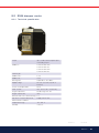
Bentone BG 650i M LMV 415 J/K User manual
- Category
- Cookers
- Type
- User manual
This manual is also suitable for

Providing sustainable energy solutions worldwide
Installation- and maintenance instruction
BG 550i/650i/700i/800i/950i M
LMV37
MB-DLE 412-415
J/K IP40
Translation of the original instructions.
CR00264 178 130 80-2 2021-07-08

2Bentone
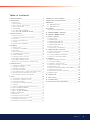
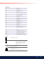
example Beispielexempel
352011030141
Designation
Type
Model
Serial no.
Motor supply
Main supply
MADE IN SWEDEN BY
LIGHT OIL 35-90kW 1,25-6,0 cSt 7-14bar
BF 1 KS 76-24
BF 1
BF 1 KS 76-24
1234567
1~230V 1,0A 50Hz IP 20
Man.Year 2019
Cap. Min-Max
3
?
1
-sv
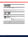
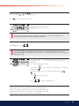
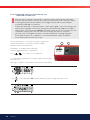
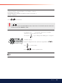
1. Manualer på övriga språk
2. www.bentone.com\
nedladdning
eller scanna QR-koden.
3. Skriv in brännarens
artikelnummer som fi nns på din
typskylt (se bild) och välj ditt
språk.
Detaljerad ecodesign information
kan laddas ner på:
www.bentone.com/ecodesign.
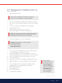
-en
1. Manuals in other languages
2. www.bentone.com\download
or scan QR-code.
3. Enter the burner`s article
number on your data plate (see
picture) and select language.
Detailed ecodesign information
can be downloaded at:
www.bentone.com/ecodesign.
-da
1. Manualer på andre sprog
2. www.bentone.com\download
eller scan QR-koden.
3. Indtast brænderens
artikelnummer, der fi ndes på
typeskiltet (se billede), og vælg
dit sprog.
Detaljerede oplysninger om
ecodesign kan downloades på:
www.bentone.com/ecodesign.
-fr
1. Manuels dans d’autres
langues
2. www.bentone.com\download
ou scannez le code QR.
3. Saisir le numéro d’article
du brûleur sur votre plaque
signalétique (consultez
l’illustration) et sélectionnez la
langue.
Des informations détaillées
sur l’écodesign peuvent être
téléchargées à l’adresse:
www.bentone.com/ecodesign.
-de
1. Gebrauchsanweisungen in
anderen Sprachen
2. www.bentone.com\download
oder scannen Sie den QR-Code.
3. Geben Sie die Artikelnummer
des Brenners auf Ihrem
Typenschild ein, (siehe Bild) und
wählen Sie die Sprache aus.
Detaillierte Informationen zum
Ecodesign können unter
www.bentone.com/ecodesign
heruntergeladen werden.
2

3 Bentone
Table of contents
1. General Information __________________________________ 4
2. Technical data _______________________________________ 7
2.1 Dimensions ______________________________________ 7
2.2 Capacity range ___________________________________ 9
2.3 Gas categories, approved gases ___________________ 10
2.4 Electric Specification _____________________________ 11
2.5 Working field ____________________________________ 12
2.6 Description BG 550, BG 650 ______________________ 14
2.7 Description BG 700, BG 800, BG 950 _______________ 16
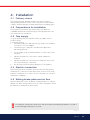
3. General instructions _________________________________ 18
3.1 General instructions ______________________________ 18
3.2 Installation and maintenance instructions ____________ 18
3.3 Instructions _____________________________________ 18
3.4 Inspection and maintenance _______________________ 18
3.5 Start up ________________________________________ 18
3.6 Commissioning of installation ______________________ 18
4. Installation _________________________________________ 19
4.1 Delivery check ___________________________________ 19
4.2 Preparations for installation ________________________ 19
4.3 Gas supply ______________________________________ 19
4.4 Electric connection _______________________________ 19
4.5 Setting brake plate and air flow _____________________ 19
4.6 Skeleton diagrams _______________________________ 20
4.7 Fitting the burner to the boiler ______________________ 21
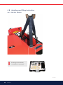
4.8 Handling and lifting instruction _____________________ 22
4.9 Handling and lifting instruction _____________________ 23
4.10 Inspection of gas nozzle before commissioning _______ 24
5. Setting the burner ___________________________________ 25
5.1 Setting the combustion assembly ___________________ 25
5.2 Setting the air damper ____________________________ 25
5.3 Setting the gas damper ___________________________ 25
5.4 Calculate prepurge time ___________________________ 26
5.5 Recommended excess air when using default setting __ 27
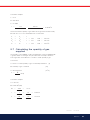
5.6 Determining the gas quantity for the system __________ 27
5.7 Calculating the quantity of gas supplied _____________ 29
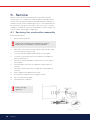
6. Service _____________________________________________ 30
6.1 Servicing the combustion assembly _________________ 30
6.2 Replacement of damper motor, air __________________ 31
6.3 Servicing air dampers _____________________________ 33
6.4 Replacement of damper motor, gas _________________ 34
6.5 Vibration ________________________________________ 35
6.6 Flame monitoring and ionisation current check ________ 36
6.7 Gas nozzle BG 550, BG 650 _______________________ 37
6.8 Gas nozzle BG 550 LN ___________________________ 37
6.9 Gas nozzle BG 700, BG 800 _______________________ 38
6.10 Gas nozzle BG 950 _______________________________ 39
6.11 UV detector _____________________________________ 40
6.12 Setting the air pressure switch _____________________ 41
6.13 Setting the min. gas pressure switch ________________ 42
6.14 Setting the power monitor _________________________ 43
6.15 Setting the max. gas pressure switch _______________ 44
7. Handing over of the installation _______________________ 45
8. Fault location, functional troubles _____________________ 45
9. Regulators _________________________________________ 46
9.1 SQM damper motor ______________________________ 47
9.2 SQM damper motor ______________________________ 49
10. Gas train _________________________________________ 51
10.1 DMK gas butterfly damper _________________________ 51
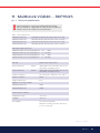
11. Multiblock VGD40… SKP15/25 _____________________ 53
12. Multi-Bloc, MB-DLE 412-420 _______________________ 57
13. Electric equipment ________________________________ 62
13.1 Safety system ___________________________________ 62
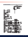
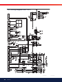
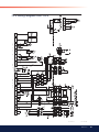
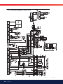
13.2 Wiring diagram __________________________________ 63
13.3 Wiring diagram RWF 50:3 _________________________ 64
13.4 Wiring diagram RWF 50:2 _________________________ 65
13.5 Wiring diagram Jumo 316 _________________________ 66
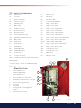
13.6 List of compnents ________________________________ 67
13.7 Components – Electrical box _______________________ 67
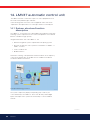
14. LMV37 automatic control unit ______________________ 68
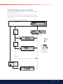
14.1 System structure/function description _______________ 68
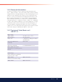
14.2 General information ______________________________ 69
14.3 Technical Data Basic unit LMV37.4... ________________ 69
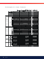
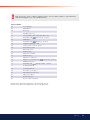
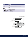
14.4 Connection and internal diagram ___________________ 74
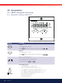
15. Operation ________________________________________ 76
15.1 LMV37 automatic control unit ______________________ 76
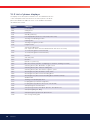
15.2 List of phase displays _____________________________ 78
15.3 Automatic control unit levels _______________________ 79
15.4 Setting the automatic control unit ___________________ 84
15.5 Backup and restore _____________________________ 103
15.6 Fault status message, display of errors and info ______ 107
15.7 Dispaly message of info __________________________ 113
15.8 Resetting the automatic control unit ________________ 114
15.9 Manual output __________________________________ 115
16. Parameter list ___________________________________ 117
17. Error code list ___________________________________ 126
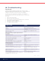
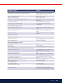
18. Troubleshooting _________________________________ 140
19. General instructions for gasburners ________________ 143

4Bentone
1. General Information
This Installation and Maintenance manual:
• is to be regarded as part of the burner and must always be kept near
the installation site.
• is intended for use by authorised personnel.
• must be read prior to installation.
• must be observed by all who work with the burner and associated
system components.
• work with the burner may only be carried out by certifi ed installers/
personnel.
Enertech AB is not liable for any typographical errors and reserves the right
to make design changes without prior notice.
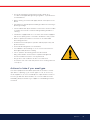
Safety instructions
• The burner may only be used for its intended purpose in accordance
with the product’s technical data.
• The burner may only be installed and operated by authorised
personnel.
• The product is packaged to prevent damage from occurring during
handling. Handle the product with care. Lifting equipment must be
used to lift larger packages.
• The products must be transported/stored on a level surface in a dry
environment, max. 80% relative humidity, no condensation.
Temperature -20 to +60 °C.
• Check that the burner is compatible with the boiler’s output range.
• All components must be installed without being bent, twisted or
subjected to mechanical or thermal forces which can affect the
components.
• The burner must be installed so that it complies with local regulations
for fi re safety, electrical safety, and fuel distribution.
• The gas outlet from the pressure regulator shall be confi gured in
accordance with applicable regulations and lead to a safe area.
• Make sure when installing the equipment that there is enough space to
service the burner.
• Permitted temperature during operation -10 to +60 °C. Max 80%
relative humidity, no condensation.
• The installer must ensure that the room has adequate air supply.
• The room must comply with local regulations pertaining to its intended
use.
• The installation site must be free of chemicals.
• Burner pipes, fan wheels and air dampers may contain sharp edges.
• The surface temperature of the burner’s components can exceed
60°C.
• Caution: The burner has moving parts, and there is risk of crushing
injuries.
172 515 01 2018-01-02

5Bentone
• The electrical installation must be professionally carried out in
accordance with applicable high voltage regulations, as per Enertech’s
recommendations.
• Before servicing, shut off the fuel supply and turn off the power to the
burner.
• Seal inspections must be performed during installation and servicing to
prevent gas leakage.
• Care should be taken by the installer to ensure that no electrical cables
or fuel lines are crushed or otherwise damaged during installation or
servicing.
• If the boiler is equipped with an access hatch, this must be equipped
with a hatch opening switch connected to the burner's safety system.
• When in operation, the burner’s noise level can exceed 85 dBA.
Use hearing protection.
• The burner must not be put into operation without proper safety and
protection devices.
• A Class BE fi re extinguisher is recommended.
• It is forbidden to alter thedesign or use accessories which have not
been approved by Enertech in writing.
• Prior to operation, the following points must be checked:
-fi tting and installation work has been completed and approved
-electrical installation has been correctly performed
-fl ue gas ducts and combustion air ducts are not blocked
-all actuators and control and safety devices are in working order and
correctly set
Actions to take if you smell gas
Turn off the equipment and the boiler. Open windows and doors. Prevent
open fl ames or sparking, e.g. do not turn lights on or off, do not use any
electrical appliances, do not use mobile phones. Open windows and doors.
Close the gas ball valve. Warn residents; do not use doorbells. Evacuate
the building. Notify the installer or gas supplier once the building has been
evacuated.

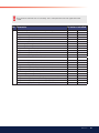
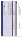
6Bentone
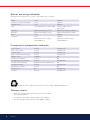
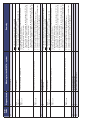
Control system 10 years 250 000 starts
Valve control system 10 years 250 000 starts
Pressure switch 10 years 250 000 starts
Ignition system with flame guard 10 years 250 000 starts
UV flame sensor 10 000 hrs N/A
Gas pressure regulators 15 years N/A
Gas valve without seal testing 10 years 250 000 starts
Gas valve with seal testing Replacement upon fault detection N/A
Gas pressure switch 10 years 250 000 starts
Safety blow-off system 10 years N/A
Damper motor N/A 500 000 starts
Contactor 10 years 500 000 starts
Burner 1 year 3 000 hrs
Inspection of electrical installation 1 year 3 000 hrs
Leakage check 1 year 3 000 hrs
Filter 1 year replacement at Δp>10 mbar 3 000 hrs replacement at
Δp>10 mbar
Electrodes Replacement/Cleaning 1 year Replacement/Cleaning 3 000 hrs
Brake disc Replacement/Cleaning 1 year Replacement/Cleaning 3 000 hrs
Motor 1 year 3 000 hrs
Fan wheel 1 Year
Replacement when cleaning
needed/imbalance
3 000 hrs
Replacement when cleaning
needed/imbalance
The burner and its components must be recycled according to applicable regulations.
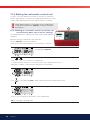
Burner servicing schedule
Servicing must be carried out once a year or after 3 000 hours of operation.
Component replacement intervals
Delivery check
• Make sure everything is delivered and the goods have not been
damaged during transit.
• If something is wrong with a delivery, report it to the supplier.
• Transport damage must be reported to the shipping company.

7 Bentone
E
H
I
C
B
E
F
G
D
A
**J
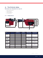
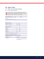
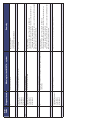
2. Technical data
Burners are intended for use at:
• Water heating generators
• Steam generators
• Industrial applications
• Hot air generators
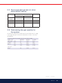
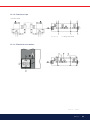
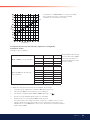
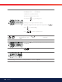
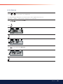
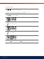
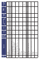
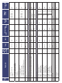
2.1 Dimensions
Type Length of
burner tube
Flange
measure A
Burner tube
measure B
Burner tube
measure C
BG 550
Standard 1 256 226
162 162Standard 2 356 326
Standard 3 456 426
BG 650 Standard 1 316 286 184 162
Standard 2 416 386
BG 700 Standard 363 328 220 205
Long variant 663 628
BG 800 Standard 396 361 261 205
Long variant 696 661
BG 950 Standard 1 350 310 280 254
/1172 525 59-2 2021-04-26

8Bentone
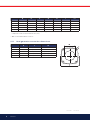
* The above dimensions are max. measurements. Depending on the
components used, the measurements may vary.
** Min. recommended distance to floor.
D E F G H I **J
BG 550 660 320 400 *590 *743 343 200
BG 650 660 320 400 *590 *743 343 200
BG 700 820 410 510 *730 *970 420 200
BG 800 820 410 510 *730 *1022 472 200
BG 950 890 410 510 *730 *1027 472 200
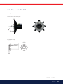
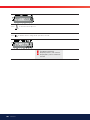
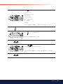
2.1.1 Heat generator connection dimensions
K
L
M
K L M
BG 550 M12 (Ø 210) Ø 255-290 Ø 170
BG 650 M12 (Ø 210) Ø 254-280 Ø 190
BG 700 M14 (Ø 280) Ø320-380 (Ø 210) Ø 230
BG 800 M14 (Ø 280) Ø320-380 (Ø 210) Ø 270
BG 950 M14 (Ø 340) Ø420-490 (Ø 260) Ø 290
172 525 59-2 2021-04-26/2

9 Bentone
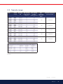
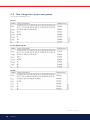
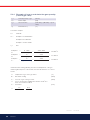
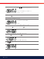
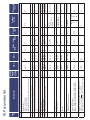
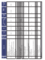
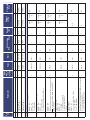
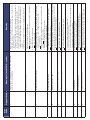
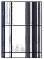
2.2 Capacity range
BG 550 G20 140-628 14 63
360
BG 550 G25 140-628 17 76
BG 550 G30 140-628 4 19
BG 550 G31 140-628 6 25
BG 650 G20 200-1125 21 118
360
BG 650 G25 200-1125 24 137
BG 650 G30 200-1125 6,2 34,6
BG 650 G31 200-1125 8,1 45,7
BG 700 G20 300-1500 31,2 157,1
360
BG 700 G25 360-1500 36,2 183
BG 700 G31 380-1650 15,4 67,1
BG 800 G20 380-2400 40 252
360
BG 800 G25 380-2400 46 293
BG 800 G31 380-2400 15,5 98
BG 950 G20 500-3200 52,6 336.8
360
BG 950 G25 500-2800 61 342
BG 950 G30 500-3200 15,4 98,5
BG 950 G31 500-3200 20 130
kWh/Nm3MJ/Nm3kcal/Nm3
G20 9.5 34.02 8126
G25 8.2 29.25 6986
G30 32.5 116.09 27728
G31 24.6 88.00 21019
Type Grade
of gas
Capacity
kW
Gas quantity
at min. power
Nm3/h 1)
Gas quantity
at max.
power Nm3/h
1)
Max.
connection
pressure
mbar
Nominal connection
pressure mbar
see data plate
see data plate
see data plate
see data plate
see data plate
1) Lower heat value Hu at normal state 15°C and 1013.25 mbar EN676.
Grade of gas
Natural gas
Natural gas
Butane
Propane
Gas quantity and capacity vary according to grade of gas and connection
pressure.
172 525 59-2 2021-04-26/3

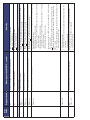
10 Bentone
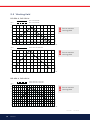
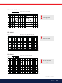
BG 550
2.3 Gas categories, approved gases
Only dry gas is permitted for use.
BG 700
BG 650, BG 800, BG 950
172 525 59-2 2021-04-26/4

11 Bentone
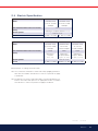
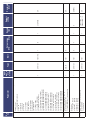
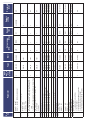
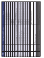
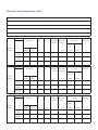
2.4 Electric Specification
Type BG 700 BG 800 BG 950
Motor 230/400V, 50Hz,
10.4/5.5A, 3.0kW,
2940rpm
230/400V, 50Hz,
20.5/12.0A,
5.5kW, 2950rpm
230/400V, 50Hz,
21.5/13.5A,
5.5kW, 2950rpm
The recommended main fuse motor C16A D20A D20A
Fitting Natural gas,
Propane
2 ½”, 1.5”
Natural gas,
Propane, Butane
3“ (2½“, 2“, 1½“)
Natural gas,
Propane, Butane
3“ (2½“, 2“, 1½“)
Control power 230V 1F~2.5A
Sound 93 dBA ± 0.5 dBA 96 dBA ± 0.5 dBA 97 dBA ± 0.5 dBA
Type BG 550 BG 650
Motor 230/400V, 50Hz,
3.5/2.5A, 0.75kW,
2860rpm
230/400V, 50Hz,
6.5/4.0A, 1.5kW,
2890rpm
The recommended main fuse motor C10A
Fitting Natural gas, Propane, Butane 1 ½”-2”
Control power 230V 1F~2.5A
Sound 89 dBA ± 0.5 dBA 91 dBA ± 0.5 dBA
172 525 59-2 2021-04-26/5
Measurements according to EN 3746: 2010
Alt.1 The sound level of the burner can be reduced by equipping the burner
with silencer. Installation must be done so it does not prevent air supply
to the burner.
Alt.2 The burner’s noise level can be reduced by connecting the burner’s air
intake to the air duct that opens into an appropriate location. Installation
must be done so it does not prevent air supply to the burner.

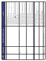
12 Bentone
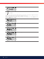
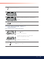
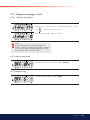
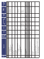
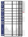
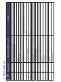
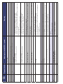
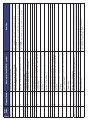
2.5 Working field
BG 550-2, BG 550 M
BG 650-2, BG 650 M
!Do not exceed
working field.
172 525 59-2 2021-04-26/6
-2
0
2
4
6
8
10
12
100 200 300 400 500 600 700
mbar
kW
G20 140-650 kW
G25 140-600 kW
160303-254
-2
0
2
4
6
8
10
12
100 200 300 400 500 600 700
mbar
kW
G30, G31 140-628 kW
160303-255
-2
0
2
4
6
8
10
12
14
16
100 200 300 400 500 600 700 800 900 1000 1100 1200
mbar
kW
G20, G25 200-1125 kW
G30, G31 200-1125 kW
160302 283-2
!Do not exceed
working field.
!Do not exceed
working field.

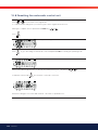
13 Bentone
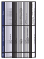
BG 800 M
BG 950 M
BG 700-2, BG 700 M
!Do not exceed
working field.
!Do not exceed
working field.
!Do not exceed
working field.
172 525 59-2 2021-04-26/7
-2
0
2
4
6
8
10
12
14
200 400 600 800 1000 1200 1400 1600
mbar
kW
G20, G25 300-1500 kW
G30, G31 380-1650 kW
160303-251
-4
0
4
8
12
16
20
24
28
32
200 400 600 800 1000 1200 1400 1600 1800 2000 2200 2400
mbar
kW
G20, G25, G30, G31 380-2400 kW
160302-280-2
-4
0
4
8
1
2
1
6
2
0
2
4
2
8
32
400 900 1400 1900 2400 2900 3400
mbar
kW
G20, G30, G31 500-3200 kW
G25 500-2800 kW
160302-287-2

14 Bentone
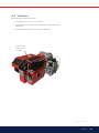
12
13
89
10
122
14
5
6
2
3
11
7
4
16
15
17
11
12
18
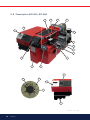
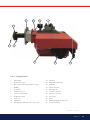
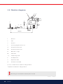
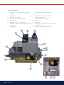
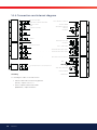
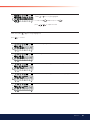
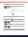
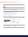
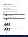
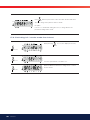
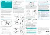
2.6 Description BG 550, BG 650
172 525 59-2 2021-04-26/8

15Bentone
16
22 21 24
920
17 19
18
1. Burner tube
2. Damper motor, gas
3. Min. gas pressure switch/tightness check
4. MultiBloc
5. Air damper
6. Damper motor, air
7. Connection gas fi ttings
8. Air pressure switch
9. Fan house
10. Sight glass
11. AZL display for LMV automatic control unit
12. Switch 0-l
13. Brake plate adjustment
14. Guide bar
15. Ignition electrode
16. Shrouded disc
17. Ionisation electrode
18. Electrical connection
19. Gas nozzle
20. Motor
21. Measuring nipple, fan pressure
22. Connection fl ange
2.6.1 Components
172 525 59-2 2021-04-26/9

16 Bentone
11
12
18
15
16
17
6
7
9
8
1
2
3
4
5
10
14
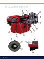
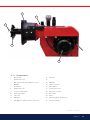
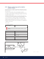
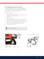
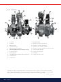
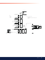
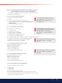
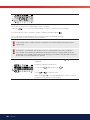
2.7 Description BG 700, BG 800, BG 950
172 525 59-2 2021-04-26/10

17 Bentone
17
19
20
21
22
2.7.1 Components
1. Burner tube
2. Damper motor, gas
3. Min. gas pressure switch/tightness check
4. MultiBloc
5. Air damper
6. Damper motor, air
7. Connection gas fittings
8. Air pressure switch
9. Fan house
10. Sight glass
11. AZL display for LMV automatic control unit
12. Switch 0-l
13.
14. Guide bar
15. Ignition electrode
16. Shrouded disc
17. Ionisation electrode
18. Electrical connection
19. Gas nozzle
20. Motor
21. Measuring nipple, fan pressure
22. Connection flange
172 525 59-2 2021-04-26/11

18 Bentone
172 515 03-2
3. General instructions
3.1 General instructions
The installation of the gas burner must be carried out in accordance with
current regulations and standards. The installers of gas burners should
therefore be acquainted with all regulations and ensure that the installation
complies with the requirements. The installation, mounting and adjustment
should be made with the greatest care and only the correct gas should be
used.
3.2 Installation and maintenance
instructions
The maintenance instructions supplied with the burner must be kept at an
easily accessible location in the boiler room.
3.3 Instructions
The user should be thoroughly in-structed in the function of the gas burner
and the whole installation. The supplier must instruct the user.
3.4 Inspection and maintenance
The unit must be serviced and maintained at the interval specified in the
service schedule. If the burner is in a dirty environment, service should be
done at more frequent intervals than specified.
3.5 Start up
After the burner has been fitted to the boiler and the electric connection, the
leakage control, the venting and the electric function test have been carried
out, the burner will be ready for start-up.
Howerer, study the sections dealing with adjustments of multi-bloc,
combustion air and combustion head. Open the ball valve and switch on the
main switch. If the burner starts the actual adjustment can be made.
3.6 Commissioning of installation
Control of the combustion. The combustion quality is checked by means
of a flue gas analysis device. Adjust the burner to appr. 20% excess air in
accordance with the table. Check the flue gas temperature. Calculate the
efficiency. Check also the actual gas volume on the gas meter so that the
correct input is achieved.

19 Bentone
172 515 03-2
4. Installation
4.1 Delivery check
Check that all has been delivered and that the goods have not been
damaged during transport. If that is not the case, please notify the delivery
company. Transport damages should be reported to the forwarding agency.
4.2 Preparations for installation
Check that the measurements and capacity range of the burner are
compatible with the boiler. The power ratings on the type plate refer to the
min. and max. power of the burner.
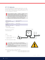
4.3 Gas supply
For good operating safety, it is important that the gas supply system is
installed correctly.
Consider the following:
1. Check that the burner is approved for the gas quality of the installation.
If not, please contact the supplier.
2. Check that the gas components of the burner are approved for
indicated gas pressure.
3. The gas supply system should be installed in accordance with current
standards.
4. Pipe lines should be run so that service on boiler and burner is
facilitated.
5. Pipe lines should be run so that eventual contaminants cannot come
into contact with the gas components.
6. Gas discharge system must be installed prior to local regulations.
4.4 Electric connection
Before starting the electric installation, the main switch must be turned off.
If the boiler has a 7-pole and a 4-pole Eurostecker connector, these usually
fit directly to the burner. If not, use the connectors included, (see connection
under Electric equipment).
4.5 Setting brake plate and air flow
Before the placing into service, the burner should be initially set according to
diagram, (see Basic settings). Note that it is only a basic setting which should
be adjusted once the burner has been started.
!If an electric connection other than the one recommended by Enertech is used, a
risk of damage and injury can arise.

21 Bentone
172 525 60 2021-04-26
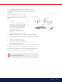
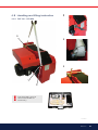
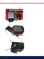
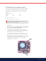
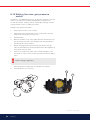
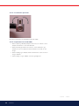
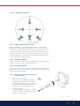
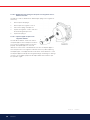
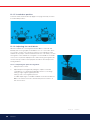
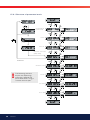
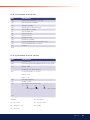
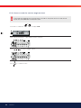
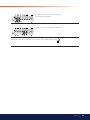
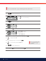
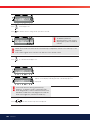
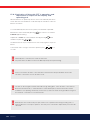
4.7 Fitting the burner to the boiler
Use 4 x M12 bolts to fit the burner to the boiler, see technical data for the
hole pattern.
To make the fitting process easier, it is possible
to separate the burner body from the gas flange
with the combustion head and valve assembly
in place.
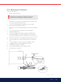
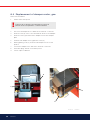
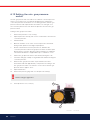
Proceed as follows:
1. Ensure that no power is going to the
burner. Switch off the main power supply
and disconnect the Euro plugs from the
burner. NOTE! If the burner is directly
connected, ensure that all components
on the burner are without power.
2. Remove the cover plate from the fan
housing.
3. Undo the nut (D) to the nozzle assembly.
(applies to BG 550 & 650; does not feature on BG 700, 800 & 950)
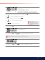
4. Disconnect the electrical cables to the valve assembly and gas damper
motor.
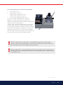
5. Undo the screws (B) on both sides.
6. Undo the end stops (C) on the guides.
7. Disconnect the ignition cable, ionisation cable and control arm
(550/650 only) from the gas nozzle.
8. Pull out the burner body from the guides and put it in a suitable place.
After separating the burner body and gas flange it is easier to fit the gas
flange with the combustion head and valve assembly to the boiler. Once the
gas flange is fitted to the boiler, it is easy to lift the burner body up onto the
guides. Assemble the burner in reverse order to its disassembly.
Service position
!Check the gas tightness.
Page is loading ...
Page is loading ...
Page is loading ...
Page is loading ...
Page is loading ...
Page is loading ...
Page is loading ...
Page is loading ...
Page is loading ...
Page is loading ...
Page is loading ...
Page is loading ...
Page is loading ...
Page is loading ...
Page is loading ...
Page is loading ...
Page is loading ...
Page is loading ...
Page is loading ...
Page is loading ...
Page is loading ...
Page is loading ...
Page is loading ...
Page is loading ...
Page is loading ...
Page is loading ...
Page is loading ...
Page is loading ...
Page is loading ...
Page is loading ...
Page is loading ...
Page is loading ...
Page is loading ...
Page is loading ...
Page is loading ...
Page is loading ...
Page is loading ...
Page is loading ...
Page is loading ...
Page is loading ...
Page is loading ...
Page is loading ...
Page is loading ...
Page is loading ...
Page is loading ...
Page is loading ...
Page is loading ...
Page is loading ...
Page is loading ...
Page is loading ...
Page is loading ...
Page is loading ...
Page is loading ...
Page is loading ...
Page is loading ...
Page is loading ...
Page is loading ...
Page is loading ...
Page is loading ...
Page is loading ...
Page is loading ...
Page is loading ...
Page is loading ...
Page is loading ...
Page is loading ...
Page is loading ...
Page is loading ...
Page is loading ...
Page is loading ...
Page is loading ...
Page is loading ...
Page is loading ...
Page is loading ...
Page is loading ...
Page is loading ...
Page is loading ...
Page is loading ...
Page is loading ...
Page is loading ...
Page is loading ...
Page is loading ...
Page is loading ...
Page is loading ...
Page is loading ...
Page is loading ...
Page is loading ...
Page is loading ...
Page is loading ...
Page is loading ...
Page is loading ...
Page is loading ...
Page is loading ...
Page is loading ...
Page is loading ...
Page is loading ...
Page is loading ...
Page is loading ...
Page is loading ...
Page is loading ...
Page is loading ...
Page is loading ...
Page is loading ...
Page is loading ...
Page is loading ...
Page is loading ...
Page is loading ...
Page is loading ...
Page is loading ...
Page is loading ...
Page is loading ...
Page is loading ...
Page is loading ...
Page is loading ...
Page is loading ...
Page is loading ...
Page is loading ...
Page is loading ...
Page is loading ...
Page is loading ...
Page is loading ...
Page is loading ...
Page is loading ...
Page is loading ...
Page is loading ...
Page is loading ...
Page is loading ...
Page is loading ...
Page is loading ...
-
 1
1
-
 2
2
-
 3
3
-
 4
4
-
 5
5
-
 6
6
-
 7
7
-
 8
8
-
 9
9
-
 10
10
-
 11
11
-
 12
12
-
 13
13
-
 14
14
-
 15
15
-
 16
16
-
 17
17
-
 18
18
-
 19
19
-
 20
20
-
 21
21
-
 22
22
-
 23
23
-
 24
24
-
 25
25
-
 26
26
-
 27
27
-
 28
28
-
 29
29
-
 30
30
-
 31
31
-
 32
32
-
 33
33
-
 34
34
-
 35
35
-
 36
36
-
 37
37
-
 38
38
-
 39
39
-
 40
40
-
 41
41
-
 42
42
-
 43
43
-
 44
44
-
 45
45
-
 46
46
-
 47
47
-
 48
48
-
 49
49
-
 50
50
-
 51
51
-
 52
52
-
 53
53
-
 54
54
-
 55
55
-
 56
56
-
 57
57
-
 58
58
-
 59
59
-
 60
60
-
 61
61
-
 62
62
-
 63
63
-
 64
64
-
 65
65
-
 66
66
-
 67
67
-
 68
68
-
 69
69
-
 70
70
-
 71
71
-
 72
72
-
 73
73
-
 74
74
-
 75
75
-
 76
76
-
 77
77
-
 78
78
-
 79
79
-
 80
80
-
 81
81
-
 82
82
-
 83
83
-
 84
84
-
 85
85
-
 86
86
-
 87
87
-
 88
88
-
 89
89
-
 90
90
-
 91
91
-
 92
92
-
 93
93
-
 94
94
-
 95
95
-
 96
96
-
 97
97
-
 98
98
-
 99
99
-
 100
100
-
 101
101
-
 102
102
-
 103
103
-
 104
104
-
 105
105
-
 106
106
-
 107
107
-
 108
108
-
 109
109
-
 110
110
-
 111
111
-
 112
112
-
 113
113
-
 114
114
-
 115
115
-
 116
116
-
 117
117
-
 118
118
-
 119
119
-
 120
120
-
 121
121
-
 122
122
-
 123
123
-
 124
124
-
 125
125
-
 126
126
-
 127
127
-
 128
128
-
 129
129
-
 130
130
-
 131
131
-
 132
132
-
 133
133
-
 134
134
-
 135
135
-
 136
136
-
 137
137
-
 138
138
-
 139
139
-
 140
140
-
 141
141
-
 142
142
-
 143
143
-
 144
144
-
 145
145
-
 146
146
-
 147
147
-
 148
148


Bentone BG 650i M LMV 415 J/K User manual
- Category
- Cookers
- Type
- User manual
- This manual is also suitable for
Ask a question and I''ll find the answer in the document
Finding information in a document is now easier with AI
Related papers
-
 Bentone BG 550i-950i M LMV 4.80 UV IP40 User manual
-
Bentone BG 700i M LMV 415-420 IP40 User manual
-
-
 Bentone BG 650i M LMV MB-DLE415 J/K IP54 User manual
-
 Bentone BG 800i M LMV 420 IP40 User manual
-
 Bentone BG 550i M LMV 412 J/K IP40 User manual
-
 Bentone BG 550i M LMV 412-420 IP40 User manual
-
 Bentone BG 650i M LMV 415-420 IP40 User manual
-
 Bentone BG 800i M LMV 4.80 UV IP40 User manual
-
 Bentone BG 550-2 BP-S4 ZRDLE 412 B07 UV User manual


Other documents
-
 Nu-Way PO660 Installation & Maintenance Manual
-
Enertech Bentone BFG1-2 H3 Installation And Maintenance Instruction
-
-
 Seltron AVD User manual
-
Eclipse T500 Actuator Operating instructions
-
 Seltron AVD Motor Actuator User manual
-
iNOXPA C-TOP Installation, Service & Maintenance Manual
-
Nilfisk SH SOLAR 7P-170/1200 G 400/3/50 EU User manual
-
-
 Kromschroder DGS Datasheet


