Page is loading ...

NPS-2HD
Heavy Duty Network Power Switches
User's Guide


Warnings and Cautions:
No Serviceable Parts Inside;
Authorized Service Personnel Only
Do not attempt to repair or service this device yourself. Internal
components must be serviced by authorized personnel only.
•
Shock Hazard - Do Not Enter
Nameplate Power Warning
This device should only be operated with the type of power
source indicated on the instrument nameplate. If you are not
sure of the type of power service available, consult your local
power company.
•
Connect unit only to a properly measured supply. Use
only three wire cord which is provided with the unit.
•
Reliable earthing of this equipment must be maintained.
Particular attention should be given to supply
connections when connecting to power strips, rather than
direct connections to the branch circuit.
Rack Mount Installation
When installing this device in an instrument rack, the following
factors must be accounted for:
1. Enclosed Racks: Enclosed racks must provide adequate
ventilation. Make certain that the rack is not overly
crowded and note that each unit in the rack generates its
own heat. An enclosed rack should have louvered sides
and a fan to circulate cooling air.
When mounting the unit in an enclosed rack with a
ventilation fan at the top of the rack, note that excessive
heat generated by devices at the bottom of the rack can be
drawn upward and into the ventilation slots of units
located at the top. Make certain to provide adequate
ventilation for equipment installed at the bottom of
the rack.
(Continued)

Rack Mount Installation (Continued)
1. Enclosed Racks (Continued):
The ambient within the rack may be greater than room
ambient. Installation should be such that the amount of air
flow required for safe operation is not compromised. The
maximum temperature for the equipment in this
environment is 45°C. Consideration should be given to the
maximum rated ambient.
Installation should be such that a hazardous stability
condition is not achieved due to uneven loading.
2. Open Racks: Make certain that the rack frame does not
block the ventilation slots on the instrument cover. If the
device is installed on sliders, check the unit when seated
all the way into the rack to make certain that ventilation
slots are not blocked.
Ventilation
Slots in the instrument cover are provided to allow ventilation
for heat dissipation. To ensure safe, reliable operation, these
openings must not be covered or blocked.
Disconnect Power
If any of the following events are noted, immediately disconnect
the unit from the outlet and contact qualified service personnel:
1. If the power cord becomes frayed or damaged.
2. If liquid has been spilled into the device or if the device
has been exposed to rain or water.

Table of Contents

List of Figures

1. Introduction
Network equipment sometimes "locks-up", requiring a service
call just to flip the power switch to perform a simple reboot. The
NPS-2HD Heavy Duty Network Power Switch gives you the
ability to perform this function from anywhere on the
LAN/WAN, or if the network is down, to simply dial-in from a
modem for out-of-band power control.
Intelligent Power Control
The NPS-2HD can communicate over any TCP/IP network using
standard Telnet, or out-of-band using an external modem and
terminal emulation. Each outlet can be assigned an individual
password, device name, reboot delay time and unique power-up
default status.
Security
Address specific IP security masks prevent unauthorized users
from accessing the NPS command menu via network. The NPS
provides two separate password security levels; System level and
User level. The System password allows access to all
configuration and command functions. The User password
allows limited access to command functions.
Easy to Use, Easy to Configure
The NPS can be configured over the network, via modem, or
locally via the NPS Console Port. Easy-to-use commands let you
assign a location name, set system parameters and view plug
status. Outlets can be switched On, Off, or Booted using plug
numbers or names.
Features:
·
Dual 20 Amp Circuits
·
On/Off/Reboot Switching
·
Integral 10Base-T Interface
·
RS232 Modem and Console Ports
·
Outlet-Specific Password Security
·
Network Security Features
·
Manual On/Off Buttons

Typographic Conventions
Throughout this manual, typefaces and characters have been used
to denote the following:
COURIER FONT Indicates characters typed on the keyboard.
For example, /ON 1 or /OFF 2.
[Bold Font] Text set in bold face and enclosed in
square brackets indicates a specific key.
For example, [Enter] or [Esc].

2. Unit Description
2.1. Front Panel
As shown in Figure 2.1, the NPS-2HD front panel includes a
series of LED indicators which function as follows:
À
ON: Lights when AC Power is applied to the NPS-2HD.
Á
RDY: Flashes when the NPS-2HD is ready to receive
commands.
Â
RXD: Lights when the NPS-2HD receives commands.
Ã
DCD: Lights when the Modem Port detects the Carrier.
Ä
NET: Lights when a Telnet session is in progress.
Å
Plug Indicators and Manual Control Buttons: An
On/Off Indicator and Manual Control Button for each
switched plug. To manually switch a plug "On" or "Off",
press and hold the appropriate Manual Control Button for
one second; the corresponding plug will be toggled
On or Off.
Note: If desired, the Manual Control Buttons can
also be disabled as described in Section 5.4.

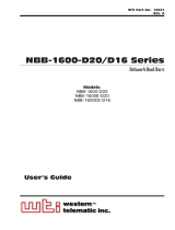
2.2. Back Panel
À
Bus 2 (Plug 2): Includes the following components:
A) Power Inlet: Supplies power for Bus 2.
B) Circuit Breaker: 115 VAC, 20 Amps
C) Switched Outlet: Each bus can switch up to 20 Amps.
Á
Bus 1 (Plug 1): Same as Item 1 above, except the Bus 1
Power Inlet supplies power to Bus 1.
Â
Network Port and Activity Indicator: A 10BaseT, RJ45
Ethernet port for connection to your TCP/IP network. To
communicate via Network, you must first specify network
parameters as described in Section 5.6.
Note: The NPS-2HD features a 10BaseT interface. When
connecting the NPS to a 100BaseT interface, note that
most 100BaseT router switches will autosense to determine
if the device is 100BaseT or 10BaseT and then configure
the network interface accordingly. If your router switch
does not autosense, then the network interface port must be
manually set to 10BaseT.
Ã
Modem Port: A Male RS-232, DB9 Connector, DTE
configuration. For connection to an external modem.
Ä
Console Port: A Male RS-232, DB9 Connector, DTE
configuration. For connection to a local PC.
Å
Option Switches: A bank of four DIP Switches which
select default settings for the baud rate and other features.
Æ
Default Button: Used in conjunction with the Reset
Button to reset the unit to defaults (see Section 4.3.)
Ç
Reset Button: Used in conjunction with the Default
Button to reset the unit to defaults (see Section 4.3.)

3. Quick Start Guide
This section provides a brief overview of basic NPS-2HD
capabilities, and describes a simple test that can be performed to
determine if the unit is operating properly and demonstrate basic
communication capabilities.
Note that this Quick Start procedure is included only to provide a
quick demonstration of basic NPS-2HD capabilities. In order to
take full advantage of the complete range of features provided by
this unit, it is strongly recommended that you should complete
the entire Installation and Configuration sections after
completing the Quick Start procedure.
1. Apply Power to the NPS-2HD: Connect the NPS-2HD to
an appropriate power source. Prior to connecting the unit
to your power supply, make certain to review the safety
precautions listed at the beginning of this User's Guide and
the cable clamp installation instructions in Section 4.1.
2. Connect a PC to the NPS-2HD: Attach a standard null
modem cable from your PC COM port to the Console Port
connector on the NPS back panel. For a description of the
port interface, please refer to Appendix A.
Note: When the NPS-2HD is shipped from the
factory, Console Port communication parameters are
set as follows: 9600 bps, 8 Data Bits, One Stop Bit,
No Parity. Although the NPS-2HD allows these
parameters to be easily redefined, for this Quick
Start procedure, it is recommended that you
configure your communications program to accept
these default parameters.
3. Access the Command Mode: Start your communications
program and then press [Enter]; the System Help Screen
should be displayed (Figure 3.1) and the NPS command
prompt should appear. For more information on command
mode access, please refer to Section 5.2.

4. Configure Network Port: In order to allow
communication with the NPS-2HD via the Network Port,
you must first define the IP Address, Subnet Mask, and
Gateway Address. At the NPS command prompt, type /N
and press [Enter] to display the Network Parameters
menu.
a) Settings for network parameters will depend on the
configuration of your individual network. Please
contact your network administrator in order to
determine the appropriate settings for the IP Address,
Subnet Mask, and Gateway Address.
b) To assign network parameters, key in the number for
the desired parameter, press [Enter], and then follow
the instructions in the resulting submenu. For
example, to define the IP Address, type 1 and
press [Enter].

5. Exit Command Mode: When you have finished setting
Network Parameters, type /X and press [Enter] to exit the
command mode at the Console Port.
Note: Only one port may access the NPS command
mode at a given time. In order to allow access to the
NPS unit via other ports, always exit from the
command mode when you are finished
communicating with the unit.
6. Connect Network Cable: Connect your network interface
to the NPS-2HD Network Port. The Network Port is an
RJ45, 10BaseT Ethernet jack, for connection to a TCP/IP
network.
Note: The NPS-2HD features a 10BaseT Interface.
When connecting to a 100BaseT interface, note that
most router switches will autosense to determine if
the device is 100BaseT or 10BaseT, and then
configure the network interface accordingly. If your
router switch does not autosense, then the network
interface port must be manually set to 10BaseT.
7. Network Access: Telnet to the NPS's IP address. For
example, if the IP address is "119.1.1.1", on a UNIX
system the Telnet command would be invoked as follows:
$ telnet 119.1.1.1 [Enter]
After the Telnet connection is established, the NPS should
display the System Help Screen and the NPS command
prompt should appear, indicating that you have
successfully accessed the NPS Command Mode via the
Network Port.

8. Test Boot Commands: When the NPS-2HD is powered
up, both switched plugs will be set in the ON position. In
order to test for proper operation, you may wish to perform
the following test. Note that it is not necessary to connect
a device to either switched outlet in order to perform
this test.
a) Reboot Plugs: To initiate a boot cycle at both plugs,
go to the NPS command prompt and type /BOOT *
and press [Enter]. Power to both plugs will be
switched OFF. After the Boot Delay Period (Default =
5 Seconds), the power to both plugs will then be
automatically switched back ON. Note that the Plug
Status Indicators on the NPS-2HD front panel will also
switch Off and On.
b) Switch Plugs OFF: To switch both plugs OFF, go to
the NPS command prompt, type /OFF * and then
press [Enter]. Power to both plugs will be switched
OFF. Note that the Plug Status Indicators will also be
switched Off.
c) Switch Plugs ON: To switch both plugs ON, go to the
NPS command prompt, type /ON * and then press
[Enter]. Power to both plugs will be switched ON.
Note that the Plug Status Indicators will also be
switched On.
9. Exit Command Mode: Type /X and press [Enter] to exit
from the NPS Command Mode, or disconnect using your
Telnet program.
This completes the introductory overview of the NPS-2HD.
Prior to installing and operating the unit, please review the
remainder of this User's Guide for important information
regarding safety considerations, as well as more detailed
installation, configuration, and operation instructions.

4. Installation
4.1. Power Connection
Note that the NPS-2HD features two separate 20 amp buses. In
order for both buses to function, power must be connected to
both input connectors on the unit's back panel.
Prior to connecting power supply cables to the unit, please refer
to the cautions below, and the cable clamp installation
instructions in Sections 4.1.1 and 4.1.2.
CAUTIONS:
•
This device should only be operated with the
type of power source indicated on the
instrument nameplate. If you are not sure of the
type of power service available, please contact
your local power company.
•
Reliable earthing (grounding) of this unit must
be maintained. Particular attention should be
given to supply connections when connecting to
power strips, rather than directly to the branch
circuit.
"Always On" Architecture: The NPS-2HD features "Always
On" architecture. This means that once the NPS-2HD is
connected to your power supply, both plugs will always be set in
the ON state, unless program commands or the Manual Control
Buttons have been used to switch the plug(s) to the OFF state.
4.1.1. Cable Clamp Installation
CAUTIONS:
•
Make certain that the unit is disconnected from
the power source before beginning this
procedure.
•
In order to reduce the chance of injury due to
electric shock, the Output Cables should be
installed before the Input Cables.

4.1.2. Output Cable Clamp
1. Loosen Screws: Locate the two screws which secure each
output jack to the NPS-2HD back panel. Carefully loosen
each screw to provide sufficient room for the cable clamp
to be attached after it is fitted to the cable.
Note: Make certain to loosen the screws enough to
allow the cable clamp to be installed, but do not
entirely remove the screws from the NPS
back panel.
2. Connect Plug: Plug the power cable from your AC
powered device into the output jack. Make certain that the
plug is firmly seated. Note that the total load for each
outlet must not exceed 20 amps.
3. Fit Clamp to Plug: Carefully slip the output cable clamp
(See Figure 4.1) over the output plug, making certain that
the two slots at the base of the clamp are properly seated
over the screws which secure the output jack to the back
panel. The U-shaped cutout, located at the back of the
clamp, should face downwards in order to allow the clamp
to fit over the cable.
4. Tighten Screws: Tighten the screws which secure the
output cable clamp to the output jack.

4.1.3. Input Cable Clamp
1. Loosen Screws: Locate the two screws which secure each
input jack to the NPS-2HD back panel. Carefull loosen
each screw to provide sufficient room for the input jack
clamp to be attached.
Note: Make certain to loosen the screws enough to allow
the clamp to be installed, but do not entirely remove the
screws from the NPS back panel.
2. Attach Clamp to Jack: Slip the input clamp into place,
making certain that the screw slots in the base of the clamp
are securely seated over the screws which secure the input
jack to the back panel. Make certain to position the clamp
so the retaining screw (see Figure 4.2) is facing upwards.
Tighten the screws to secure the clamp to the input jack.
3. Connect Plug: Slide the input plug into the cable clamp.
If necessary, loosen the retaining screw to provide room
for the plug. Make certain that the plug is firmly seated in
the jack, and then tighten the retaining screw to secure the
clamp to the cable.

4.2. Option Switches
The Option Switches select default settings for the Baud Rate,
Command Echo, Boot Delay and Disconnect Timeout. Default
settings selected via the Option Switches will be used when the
unit is reset to default parameters as described in Section 4.3.
Notes:
•
Although the Option Switches select default
settings for these features, the NPS-2HD
configuration menus can also be used to select
operating parameters as described in Section 5.
•
If Option Switch settings are changed, the new
settings will not be applied until the unit is reset
as described in Section 4.3.
Option Switch settings are described below:
Baud Rate: The default baud rate for the Console Port and
Modem Port.
Boot Delay: The default Boot Delay setting. When a boot cycle
is initiated, the Boot Delay determines the length of time that
the switched outlet will remain off until power is restored.
Command Echo: The default setting for the Command Echo for
the Console Port, Modem Port and Network Port. When
enabled, commands entered at your keyboard will be sent to
the NPS and echoed back to your display monitor.
Disconnect Timeout: The default Disconnect Timeout value.
This determines how long the NPS will wait for additional
commands before automatically disconnecting. Note that
when the NPS times out, DTR will drop, and the modem
disconnect and initialize strings will be sent.
Switch Function Up Down
* = Factory Setting

4.3. Reset Unit to Defaults
If Option Switch settings are changed, the new settings will not
be applied until the unit is reset to default settings. There are
two ways to reset the unit to defaults:
Note: When these reset procedures are performed,
all user selected parameters, including passwords
and port names will be lost. Prior to performing
these reset procedures, it is strongly recommended
to save configuration parameters to an ASCII text
file as described in Section 7.
4.3.1. Default Button / Reset Button (Local)
Typically, this method is used when you have immediate access
to the installation site.
1. Simultaneously press the DEFAULT and RESET buttons,
located on the NPS-2HD Back Panel.
2. Release the RESET button, wait for approximately five
seconds, and then release the DEFAULT button.
4.3.2. Default Parameters Option
To reset the unit to default parameters using the General
Parameters Menu's "Default Parameters" option, proceed
as follows. Note that this method requires that you have already
connected a local or remote PC to the unit and have accessed the
command mode.
1. Access the NPS Command Mode (see Section 6.1).
2. At the NPS> command prompt, type /G and press [Enter].
The General Parameters menu will appear.
3. From the General Parameters menu, type A and press
[Enter]. If command confirmation is enabled, the unit
will display a "Sure?" prompt. Type Y and press [Enter]
to proceed with the reset procedure. After a brief pause,
parameters will be reset to default values.
Note: If the Default Parameters function is invoked
via the Network Port, the IP Address will not be
reset. If this function is invoked via the Console
Port or Modem Port, the IP Address will be reset.

4.4. Console Port Connection
The Console Port is a male, DB9 connector, wired in a DTE
configuration (similar to an AT computer), which is used for
connection to a local PC or control device. Appendix A
describes the Console Port interface.
4.5. Connecting an External Modem
When connecting directly to an external modem, use a standard
DB9 AT to Modem cable. Section 5.4 describes the procedure
for defining the modem command strings. Appendix A describes
the modem port interface.
4.6. Connecting the Network Cable
The Network Port is an RJ45 Ethernet jack, for connection to a
TCP/IP network. Connect your 10Base-T cable to the Network
Port. Before attempting to access the unit via network, please
assign the IP Address, Gateway Address and Subnet Mask as
described in Section 5.6.
Note: The NPS-2HD features a 10BaseT interface.
When connecting the NPS to a 100BaseT interface,
note that most router switches will autosense to
determine if the device is 100BaseT or 10BaseT and
then configure the network interface accordingly. If
your router switch does not auto-configure for
10BaseT vs. 100BaseT, then the network interface
port must be manually set to 10BaseT.
/