
ENGLISHFRANÇAISESPAÑOL
page 1page 21página 41
1
Middleby Cooking Systems Group 1400 Toastmaster Drive Elgin, IL 60120 (847)741-3300 FAX (847)741-4406
OWNER'S OPERATING
& INSTALLATION
MANUAL
© 2000 Middleby Marshall, Inc.
is a registered trademark of Middleby Marshall, Inc. All rights reserved.
Model PS314SBI Gas and Electric
Ovens
PS314SBI
Gas and Electric (AGA/UL)
ENGLISH/French/Spanish
P/N 42447
Rev. B V1 2/00
Models:
PS314SBI
Combinations:
Single Lower Oven

2
ENGLISH
Middleby Cooking Systems Group 1400 Toastmaster Drive Elgin, IL 60120 USA (847)741-3300 FAX (847)741-4406
24-Hour Service Hotline: 1-(800)-238-8444
www.middleby.com
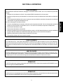
NOTICE:
This Owner's Operating and Installation Manual should be given to the user. The operator of the oven should
be familiar with the functions and operation of the oven.
This manual must be kept in a prominent, easily reachable location near the oven.
Gas ovens are designed for use with EITHER natural gas OR liquid propane gas, as specified on the serial plate.
Where permitted by local and national codes, the oven can be converted from natural gas to propane operation,
or from propane to natural gas operation. This conversion requires the installation of the appropriate Middleby
Marshall Gas Conversion Kit by an Authorized Service Agent.
It is suggested to obtain a service contract with a Middleby Marshall Authorized Service Agent.
WARNING
POST, IN A PROMINENT LOCATION, THE EMERGENCY TELEPHONE NUMBER OF YOUR LOCAL GAS
SUPPLIER AND INSTRUCTIONS TO BE FOLLOWED IN THE EVENT YOU SMELL GAS.
Instructions to be followed in the event the user smells gas shall be obtained by consulting the local gas
supplier. If the smell of gas is detected, immediately call the emergency phone number of your local Gas
Company. They will have personnel and provisions available to correct the problem.
FOR YOUR SAFETY
Do not store or use gasoline or other flammable vapors or liquids in the vicinity of
this or any other appliance.
WARNING:
Improper installation, adjustment, alteration, service or maintenance
can cause property damage, injury or death. Read the installation,
operating and maintenance instructions thoroughly before installing
or servicing this equipment.
NOTICE: CONTACT YOUR MIDDLEBY MARSHALL AUTHORIZED SERVICE AGENT TO PERFORM MAINTENANCE
AND REPAIRS. AN AUTHORIZED SERVICE AGENCY DIRECTORY IS SUPPLIED WITH YOUR OVEN.
NOTICE: Using any parts other than genuine Middleby Marshall factory manufactured parts relieves the manufacturer of
all warranty and liability.
NOTICE: Middleby Marshall (Manufacturer) reserves the right to change specifications at any time.
NOTICE: The equipment warranty is not valid unless the oven is installed, started and demonstrated under the supervision
of a factory certified installer.
IMPORTANT
An electrical wiring diagram for the oven is located inside the machinery
compartment.
IMPORTANT
It is the customer's responsibility to report any concealed or non-concealed damage
to the freight company. Retain all shipping materials until it is certain that the
equipment has not suffered concealed shipping damage.
Retain This Manual For Future Reference

3
ENGLISH
SECTION 1 - DESCRIPTION .................................................... 4
I. OVEN USES ............................................................. 4
II. OVEN COMPONENTS ............................................. 4
A. Conveyor Drive Motor ........................................ 4
B. End Trays .......................................................... 4
C. Conveyor ........................................................... 4
D. End Plugs ......................................................... 4
E. Cool Rear Panels ............................................. 4
F. Cool Front Panel ............................................... 4
G. Machinery Compartment Access Panel ........... 4
H. Control Compartment Access Panel ............... 4
I. Control Panel .................................................... 4
J. Serial Plate........................................................ 4
K. Crumb Pans ..................................................... 4
L. Gas Burner........................................................ 4
M. Blowers ............................................................. 4
N. Air Fingers ......................................................... 4
III. OVEN SPECIFICATIONS ......................................... 4
A. Dimensions ...................................................... 4
B. General Specifications ..................................... 4
C. Gas Orifice and Pressure Specifications ......... 4
D. Electrical Specifications - Gas Ovens .............. 4
E. Electrical Specifications - Electric Ovens ......... 5
SECTION 2 - INSTALLATION .................................................. 5
I. INSTALLATION KIT .................................................. 6
A. Components ..................................................... 6
B. Additional Components - Gas Ovens .............. 6
II. VENTILATION SYSTEM ............................................ 6
A. Requirements................................................... 6
B. Recommendations........................................... 6
C. Other Ventilation Concerns .............................. 7
III. ASSEMBLY ............................................................... 7
A. Legs/Casters Installation ................................. 7
B. Restraint Cable Installation .............................. 7
TABLE OF CONTENTS
IV. THERMOCOUPLE INSTALLATION .......................... 8
V. CONVEYOR INSTALLATION .................................... 8
VI. FINAL ASSEMBLY ................................................... 10
VII. ELECTRICAL SUPPLY ........................................... 11
A. Electric Ovens .................................................. 11
B. Gas Ovens ....................................................... 11
C. Ovens with External Transformers .................. 11
D. Connection....................................................... 11
VIII. GAS SUPPLY .......................................................... 12
A. Connection....................................................... 12
B. Gas Conversion ............................................... 12
SECTION 3 - OPERATION ...................................................... 13
I. LOCATION AND DESCRIPTION OF CONTROLS .. 13
A. BLOWER ( ) Switch ...................................... 13
B. HEAT ( ) Switch ............................................ 13
C. CONVEYOR ( ) Switch ............................... 13
D. Conveyor Speed Controller ............................. 13
E. Digital Temperature Controller ........................ 13
F. Machinery Cpt. Access Panel Safety Switch .... 13
II. NORMAL OPERATION, STEP-BY-STEP ................. 14
A. Daily Startup Procedures ................................. 14
B. Daily Shutdown Procedures ............................ 14
III. QUICK REFERENCE: DIGITAL TEMP CONTROL . 15
IV. QUICK REFERENCE: TROUBLESHOOTING ........ 16
SECTION 4 - MAINTENANCE ................................................. 17
I. MAINTENANCE - DAILY .......................................... 18
II. MAINTENANCE - MONTHLY ................................... 18
III. MAINTENANCE - EVERY 3 MONTHS ..................... 19
IV. MAINTENANCE - EVERY 6 MONTHS ..................... 19
V. MAINTENANCE - EVERY 12 MONTHS ................... 19
V. KEY SPARE PARTS KIT .......................................... 20
A. Components .................................................... 20
B. Additional Components - Gas Ovens ............. 20
page page

4
ENGLISH
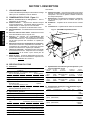
SECTION 1 - DESCRIPTION
I. OVEN USES
The PS314SBI oven is optimized to melt cheese for use on
sandwiches and other food products.
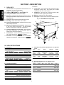
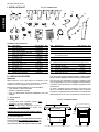
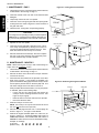
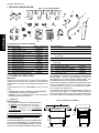
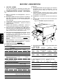
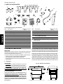
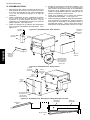
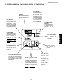
II. OVEN COMPONENTS - see Figure 1-1.
A. Conveyor Drive Motor: Moves the conveyor.
B. End Trays: Catch the food product as it exits the conveyor.
End trays are available in single and double versions for the
PS314SBI oven.
C. Conveyor: Moves the food product through the oven.
D. End Plugs: Allow access to the oven's interior.
E,F.
Cool Front and Rear Panels: Reduce direct user contact
with the body of the oven.
G. Machinery Compartment Access Panel: Allows access
to the oven's interior components. No user-servicable
parts are located in the machinery compartment.
H. Control Compartment Access Panel: Allows access to
the control components. No user-servicable parts are
located in the control compartment.
I. Control Panel: Location of the operating controls for the
oven. Refer to Section 3, Operation, for details.
J. Serial Plate: Provides specifications for the oven that affect
installation and operation. Refer to Section 2, Installation.
Fig. 1-1 - PS314SBI Oven Components
J
III. OVEN SPECIFICATIONS
A. Dimensions
Overall Height - inc. top and 9"/229mm legs 54" (1372mm)
Overall Depth - inc. front and rear shrouds
with single exit tray 38-1/2" (978mm)
with double exit trays 39-3/4" (1010mm)
Overall Length - inc. exit tray(s) 83-1/4" (2115mm)
Conveyor Width 24" (610mm)
Recommended Minimum Clearances
Rear of oven (inc. rear shrouds) to wall 1" (25mm)
Conveyor extension (right) or end tray(s) (left) to wall
0" (0mm)
Not Shown:
K. Crumb Pans: Catch crumbs and other material that drop
through the conveyor belt. One crumb pan is located
underneath each end of the conveyor.
L. Gas Burner: Gas ovens only. Heats air, which is then
projected to the air fingers by the blowers.
M. Blowers: Project hot air to the air fingers.
N. Air Fingers: Project streams of hot air onto the food product.
B
F
C
D
G
A
H,I
E
B. General specifications
Weight 1080 lbs. (497kg)
Shipping Weight 1370 lbs. (630kg)
Shipping Carton Vol. 105 ft.
3
/2.98m
3
Rated Heat Input
Gas 135,000 BTU (34,020kcal,40kw/hr)
Electric 26kw/hr.
Max. Op. Temp. 550°F/288°C
Air Blowers
2 blowers at 1550 ft.
3
(43.9m
3
)/min. at 1700
RPM, 0.88" (2.2cm) water static pressure
Air Jet Velocity (avg.) 2600 ft./min. (1320cm/sec.)
Warmup Time 15 minutes
C. Gas orifice and pressure specifications - for gas-fired
ovens
Main Pilot Bypass Supply (inlet) Manifold
orifice I.D. orifice I.D. orifice I.D. pressure pressure
Natural Gas
0.219 0.028 0.065/#53 drill 6-12" W.C. 3-1/2" W.C.
5.56mm 0.71mm 1.65mm 14.9-29.9mbar 8.7mbar
Propane
0.134" 0.018" 0.034"/#62 drill 11-14" W.C. 10" W.C.
3.40mm 0.46mm 0.86mm 27.4-34.9mbar 24.9mbar
D. Electrical specifications - for gas-fired ovens
Main Blower Control Circuit Current
Voltage Voltage Phase Freq. Draw Poles Wires
208-240V 120V 1 Ph 60Hz 10A 3 Pole 4 Wire (2 hot,
1 neut, 1 gnd)
208-240V 120V 1 Ph 50/60Hz 10A 2 Pole 3 Wire
(export) (transformer) (2 hot, 1 gnd)
200-220V 120V 1 Ph 50/60Hz 10A 2 Pole 3 Wire
(export) (transformer) (2 hot, 1 gnd)

5
ENGLISH
SECTION 2 - INSTALLATION
IMPORTANT: Additional electrical information is provided on the oven's serial plate, and on the wiring diagram inside the
machinery compartment.
WARNING
Keep the appliance area free and clear of combustibles.
CAUTION
For additional installation information, refer to the following documents:
PS360 Pre-Installation Procedures Manual (Middleby Marshall P/N 88210-0024)
PS360 Installation Manual (Middleby Marshall P/N 88210-0025)
Or, contact your local Authorized Service Agent.
NOTE
There must be adequate clearance between the oven and combustible construction. Clearance
must also be provided for servicing and for proper operation.
NOTE
An electrical wiring diagram for the oven is located inside the machinery compartment.
NOTE
All aspects of the oven installation, including placement, utility connections, and ventilation requirements, must
conform with any applicable local and national codes. These codes supercede the requirements and guide-
lines provided in this manual.
NOTE
In U.S.A., the oven installation must conform with local codes, or in the absence of local codes, with the
National Fuel Gas Code, ANSI Z223.1. The oven, when installed, must be electrically grounded in accordance
with local codes, or in the absence of local codes, with the National Electrical Code (NEC), or ANSI/NFPA70.
NOTE
In Canada, the oven installation must conform with local codes, or in the absence of local codes, with the
Natural Gas Installation Code, CAN/CGA-B149.1, or the Propane Gas Installation Code, CAN/CGA-B149.2, as
applicable. The oven, when installed, must be electrically grounded in accordance with local codes, or in the
absence of local codes, with the Canadian Electrical Code CSA, C22.2, as applicable.
NOTE
For Australian installation, the oven installation must conform with AGA Code, AG601, and with any require-
ments of the appropriate statutory authority.
E. Electrical specifications - for electrically-heated ovens
Main Blower Control Current kW
Voltage Circuit Voltage Phase Freq. Draw Rating Poles Wires
208-240V 120V 3 Ph 60 Hz 67.3A at 208V 26.0 kW at 208V 4 Pole 5 Wire (3 hot, 1 neut, 1 gnd)
(with 3 Ph blower motors) 58.4A at 240V 26.0 kW at 240V
208-240V 120V 3 Ph 60 Hz 67.3A at 208V 26.0 kW at 208V 4 Pole 5 Wire (3 hot, 1 neut, 1 gnd)
(with 1 Ph blower motors) 58.4A at 240V 26.0 kW at 240V
200-220V (export) 120V (transfomer) 3 Ph 50/60 Hz 67.3A at 208V 24.3 kW at 208V 3 Pole 4 Wire (3 hot, 1 gnd)
53.5A at 220V 20.4 kW at 220V
240V (export) 120V (transformer) 3 Ph 50/60 Hz 58.4A 26.0 kW 3 Pole 4 Wire (3 hot, 1 gnd)
380V (export) 120V (transformer) 3 Ph 50/60 Hz 36.8A 24.3 kW 3 Pole 4 Wire (3 hot, 1 gnd)
400-416V (export) 120V (transfomer) 3 Ph 50/60 Hz 33.8A 24.3 kW 3 Pole 4 Wire (3 hot, 1 gnd)
480V 120V (transformer) 3 Ph 60 Hz 29.2A 26.0 kW 3 Pole 4 Wire (3 hot, 1 gnd)
SECTION 1 - DESCRIPTION
WARNING
Do not obstruct the flow of combustion and ventilation air to and from your oven. There must be no
obstructions around or underneath the oven.

6
ENGLISH
I. INSTALLATION KIT
Fig. 2-1 - Installation Kit
18"
458mm
18"
458mm
12"
305mm
3"
76mm
2"/51mm minimum
II. VENTILATION SYSTEM
IMPORTANT
Where national or local codes require the installation of fire
suppression equipment or other supplementary equipment,
DO NOT mount the equipment directly to the oven.
MOUNTING SUCH EQUIPMENT ON THE OVEN MAY:
VOID AGENCY CERTIFICATIONS
RESTRICT SERVICE ACCESS
LEAD TO INCREASED SERVICE EXPENSES FOR THE
OWNER
A. Requirements
CAUTION
A mechanically driven ventilation system is RE-
QUIRED for gas oven installations.
A mechanically driven ventilation system is
STRONGLY RECOMMENDED for electric oven
installations.
PROPER VENTILATION OF THE OVEN IS THE RE-
SPONSIBILITY OF THE OWNER.
B. Recommendations
NOTE THAT THE HOOD DIMENSIONS SHOWN IN
FIGURE 2-2 ARE RECOMMENDATIONS ONLY. LO-
CAL AND NATIONAL CODES MUST BE FOLLOWED
WHEN INSTALLING THE VENTILATION SYSTEM.
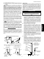
Fig. 2-2 - Ventilation System
1
2
3
7
14
15
18
19
4
5
6
16 17
12
13
8
9
10
Item Description Part Number Qty.
1 Legs, adjustable 22450-0028 4
2 Caster (Rear), Swivel 22290-0010 2
3 Caster (Front), Swivel, with brake 22290-0009 2
4 Screw, hex, 3/8-16 x 1" 220373 16
5 Lockwasher, 3/8" 21422-0001 16
6 Flat washer, 3/8" 21416-0001 16
7 Leg, 9" (229mm) 34684 4
8 Screw, hex, 3/4-10 x 2" 21321-0016 7
9 Lockwasher, 3/4" 21421-0003 8
10 Flat washer, 3/4" 21411-0019 8
11 Shoulder eyebolt, 3/4"-10 x 2" 42440 1
12 Restraint Cable Assembly 22450-0228 1
A.Installation kit components
13 Thermocouple 33812-1 1
14 Cable Clamp 27276-0001 1
15 Screw, #10-32 x 3/8" 21256-0008 1
16 Model PS314SBI Owner's Operating 42447 1
and Installation Manual
17 Authorized Service Agency Listing 1002040 1
B. Additional installation kit components for gas ovens
18 Gas hose, flexible 22361-0001 1
19 Flue vent, 14" (356mm) 30773 1
20 Screw, hex, #2PT 10-16 x 3/4" HWH 21292-0001 2
21 Screw, #10-32 x 3/8" 21256-0008 1
ANY APPLICABLE LOCAL AND NATIONAL CODES SUPER-
SEDE THE RECOMMENDATIONS SHOWN IN THIS MANUAL.
The rate of air flow exhausted through the ventilation system
may vary depending on the oven configuration and hood design.
Consult the hood manufacturer or ventilation engineer for these
specifications.
To avoid a negative pressure condition in the kitchen area,
return air must be brought back to replenish the air that was
exhausted. A negative pressure in the kitchen can cause heat-
related problems to the oven components as if there were no
SECTION 2 - INSTALLATION
11
Item Description Part Number Qty.
20
21

7
ENGLISH
SECTION 2 - INSTALLATION
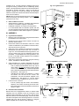
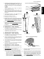
III. ASSEMBLY
A. Legs/Casters Installation
1. Move the oven to its final location using the casters that are
pre-attached to the bottom panel.
2. Elevate the oven until its bottom surface is at least 18"
(457mm) above the floor.
3. Remove the casters from the bottom of the oven. These
casters are attached for pre-installation movement ONLY,
and may not be left on the oven.
4. Attach one of the 9" (229mm) leg extensions to the REAR
DRIVE-END (rear left) corner of the oven, as shown in
Figure 2-3. On the OUTSIDE hole of the leg extension, use
one 3/4"-10 hex screw, one 3/4" lockwasher, and one 3/4"
flat washer. On the INSIDE hole of the leg extension, use
the 3/4"-10 shoulder eyebolt (supplied in the Installation
Kit) in place of the screw.
5. Attach the 3 remaining leg extensions using the remaining
screws, lockwashers, and flat washers.
6. Attach EITHER the 6" (152mm) adjustable legs OR the
casters to the bottom of the 9" leg extensions, as follows:
THE 6" (152mm) ADJUSTABLE LEGS may only be
used if there is at least 24" (610mm) service access
on ALL FOUR sides of the oven. To attach the adjustable
legs, screw the threaded stud into the center hole of the
leg extension. See Figure 2-4.
CASTERS may be used in all installations. To attach
the casters, use the 3/8"-16 hex screws, 3/8"
lockwashers, and 3/8" flat washers supplied in the
Installation Kit. See Figure 2-4. The two locking
casters should be installed at the front of the oven.
7. Lower the oven to the floor.
If the 6" (152mm) legs were used in the installation,
adjust the "foot" section of each leg to level the oven.
If the casters were used in the installation, lock the front
casters in place.
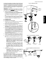
B. Restraint Cable Installation
Because the oven is equipped with casters, a restraint cable
assembly must be installed to limit the movement of the
appliance without depending on the connector and the quick
disconnect device or its associated piping. Anchor one end of
the cable to the eyebolt on the left rear leg extension. Anchor the
opposite end to the wall as shown in Figure 2-5, using the
eyebolt supplied with the restraint cable assembly.
Fig. 2-3 - Leg Extensions
Fig. 2-4 - Adjustable Legs and Casters
Fig. 2-5 - Installing the Restraint Cable
ventilation at all. The best method of supplying return air is
through the heating, ventilation and air conditioning (HVAC)
system. Through the HVAC system, the air can be temperature-
controlled for summer and winter. Return air can also be
brought in directly from outside the building, but detrimental
effects can result from extreme seasonal hot and cold tempera-
tures from the outdoors.
NOTE: Return air from the mechanically driven system
must not
blow at the opening of the baking chamber. Poor oven baking
performance will result.
C. Other ventilation concerns
Special locations, conditions, or problems may require the
services of a ventilation engineer or specialist.
Inadequate ventilation can inhibit oven performance.
It is recommended that the ventilation system and duct
work be checked at prevailing intervals as specified by the
hood manufacturer and/or HVAC engineer or specialist.
Flat
washer
Lock
washer
Hex
screw
Eyebolt (this
leg extension
only)
Rear of oven
Drive end
(left side of
oven)
Adjustable
leg
Flat
washer
Lock
washer
Hex
screw
Caster with brake -
front legs
Caster without
brake - rear legs
OR OR
3/4 (19mm)
eyebolt
Restraint cable
assembly
Eyebolt on
left rear leg
extension
Wall of
structure

8
ENGLISH
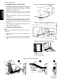
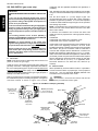
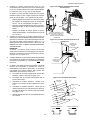
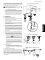
IV. THERMOCOUPLE INSTALLATION
1. Install the thermocouple sensing bulb into the hole in the
rear of the oven, as shown in Figure 2-6. Fasten the
thermocouple in place using the #10-32 x 3/8" screw
supplied in the Installation Kit.
2. Thread the thermocouple lead(s) through the grommet
and into the machinery compartment, as shown in Figure
2-6.
3. Remove the right-side access panel of the machinery
compartment.
4. Thread the thermocouple lead(s) through the side of the
machinery compartment as shown in Figure 2-7, and into
the electrical box (at the right-front of the machinery com-
partment).
5. Connect the thermocouple leads to the temperature con-
troller as shown in Figure 2-8.
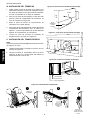
V. CONVEYOR INSTALLATION
NOTE
The conveyor assembly MUST be inserted from the drive end
of the oven.
1. Lift the conveyor and position it in the oven as shown in
Figure 2-9.
2. Continue moving the conveyor into the oven until the lip on
the bottom edge of the frame butts firmly against the end
plug.
8=White=Positive
7=Red=Negative
R=No Connection
Ground=Shielded cable
Figure 2-6 - Thermocouple Installation Location
Figure 2-7 - Placing the Thermocouple Leads
Figure 2-8 - Thermocouple Lead Connections
Grommet-
protected hole
SECTION 2 - INSTALLATION
Thermocouple
Figure 2-9 - Conveyor Installation
1 2 3
Lip on bottom
edge of frame fits
against end plug
Unfold
conveyor
Slide into drive
end of oven

9
ENGLISH
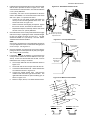
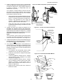
3. Install the drive chain between the conveyor drive sprocket
and the motor sprocket as shown in Figure 2-10. Then,
check the tension of the drive chain. The chain should have
a 1/2" (13mm) deflection.
If necessary, the motor can be repositioned to allow the
chain to be installed, or to correct the tension of the chain
after it is in place. To reposition the motor:
Loosen the two hex head screws that fasten the
conveyor motor's mounting bracket to the oven. The
screws are shown in Figure 2-10.
Raise or lower the motor slightly, as required. Tighten
the two hex screws, and check the chain tension.
Repeat these steps as necessary until the drive chain
has the correct 1/2" (13mm) deflection.
4. Check the tension of the conveyor belt at the IDLER (right)
end of the conveyor, by lifting the center of the belt straight
up with your fingers as shown in Figure 2-11. The belt
should lift between 2-3" (50-75mm). DO NOT OVER-
TIGHTEN THE CONVEYOR BELT.
NOTE:
If necessary, the belt tension can be adjusted by turning the
conveyor adjustment screws, located at the idler (right) end
of the conveyor. See Figure 2-11.
5. Check for freedom of movement of the conveyor belt by
pulling it for about 2-3 feet (60 to 90 cm) with your fingers.
The conveyor must move freely.
6. If necessary, links can be added to or removed from the
conveyor belt to achieve the correct deflection of 2-3" (50-
75mm). If links must be removed from the belt, it can be
reattached to the conveyor as follows:
a. The conveyor belt links must be oriented as shown in
Figure 2-12.
b. The smooth side of the conveyor belt must face UP.
c. Connect the inside master links. Check that the links
are oriented as shown in Figure 2-12.
d. Connect the outside master links. Note that the
outside master links have right and left sides. The
right-side master link has an open hook facing you, as
shown in Figure 2-12.
e. Return to Step 4, above, to re-check the belt tension.
SECTION 2 - INSTALLATION
Figure 2-10 - Drive Motor and Drive Chain
Loosen hex screws and
slide motor up or down to
adjust belt tension
Drive chain
Motor
Figure 2-11 - Conveyor belt tension
Belt deflection
should be 2-3
(50-75mm)
Lift belt straight
up as shown
Adjust tension by
turning screws (2)
Figure 2-12 - Master link orientation
Direction of
travel
Correct outside
master link
orientation
CORRECT inside master
link orientation
INCORRECT inside master
link orientation

10
ENGLISH
SECTION 2 - INSTALLATION
Figure 2-13 - Final Assembly - Front
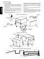
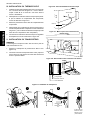
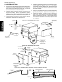
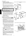
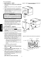
VI. FINAL ASSEMBLY
1. For gas ovens, attach the flue vent to the rear wall of the oven
as shown in Figure 2-13. Use one #10-16 x 3/8" screw and
two #10-32 x 3/4" screws. All three screws are provided in
the Installation Kit.
2. Install the motor housing, and secure it in place with its five
mounting screws. Two screws are located on the back wall
of the oven, while three are located on the hanger bracket
on the left end panel. See Figure 2-13.
3. Install the conveyor extension covers over the ends of the
conveyor frame. See Figure 2-13.
4. Check that the cool panels are properly mounted, as shown
in Figures 2-13 and 2-14. Slots on the back of the panels
fit over the hangers on the walls of the oven. One cool panel
is attached to the front of the oven, while two are attached
to the rear.
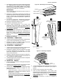
5. Attach the exit tray(s) at the drive (left) end of the conveyor.
See Figure 2-15.
6. Install the crumb trays underneath the conveyor as shown
in Figure 2-15. First, place the inside edge of the tray onto
the bracket attached to the end plug. Then, swing the
outside edge of the tray up and into place.
Figure 2-14 - Final Assembly - Rear
Motor
shroud
3 upper
screws
Extension cover
(idler end)
Front cool
panel
Hangers on oven
wall fit into slots on
cool panels
Extension cover
(drive end)
2 rear
screws
Flue vent
(gas ovens
only)
Figure 2-15 - Final Assembly - Exit Tray(s) and Crumb Trays
2 rear
#10-16 x 3/4"
screws
Rear cool
panels
Drive-end rear
panel notched for
motor shroud
1 bottom
#10-32 x 3/8"
screw
Crumb tray
Exit tray(s)
Conveyor extension Conveyor frame

11
ENGLISH
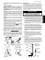
Figure 2-17 - Utility Connection Locations
Figure 2-18 -
Flexible Gas Hose
Installation
Appliance
Connection/Male
Nipple
Flexible
Gas Hose
Full-Flow Gas
Shutoff Valve
To Gas
Supply Pipe
90°
Elbow
Serial plate location
VII. ELECTRICAL SUPPLY (all ovens)
WARNING
Authorized supplier personnel normally accomplish
the connections for the ventilation system, electric supply,
and gas supply, as arranged by the customer. Following
these connections, the factory-authorized installer can
perform the initial startup of the oven.
NOTE: The electric supply installation must satisfy the
requirements of the appropriate statutory authority, such as the
National Electrical Code (NEC), ANSI/NFPA70, (U.S.A.); the
Canadian Electrical Code, CSA C22.2; the Australian Code
AG601; or other applicable regulations.
NOTE: The electric supply connection must meet all national
and local electrical code requirements.
NOTE: It may be necessary to temporarily remove the rear cool
panels to connect the electrical supply.
Check the oven serial plate before making any electric supply
connections. Electric supply connections must agree with data
on the oven serial plate. The location of the serial plate is shown
in Figure 2-16.
A fused disconnect switch or a main circuit breaker (customer
furnished) MUST be installed in the electric supply line for each
oven cavity. It is recommended that this switch/circuit breaker
have lockout/tagout capability.
The supply conductors must be of the size and material (cop-
per) recommended. Refer to the wiring diagram inside the
machinery compartment or control compartment of the oven.
Electrical specifications are also listed on the oven's serial
plate (Figure 2-16) and in the
Electrical Specifications tables
(on Pages 4-5).
The oven requires a ground connection to the oven ground
screw located in the electrical junction box. (The box is shown
in Figure 2-17.) If necessary, have the electrician supply the
ground wire. Do NOT use the wiring conduit or other piping for
ground connections!
CAUTION
Before connecting incoming power to the oven, measure the
voltage of each input leg to neutral. The expected voltage is
approximately 120V. ANY voltage reading exceeding 130V
indicates that the supply has a high leg. CONNECTING A
HIGH LEG TO THE OVEN VOIDS ALL OVEN WARRANTIES.
Connecting a high leg to the black lead of the oven can
severely damage the ovens electrical and electronic
components.
CAUTION
DO NOT CONNECT BLACK WIRE TO HIGH LEG.
VOLTAGE OF THE BLACK AND WHITE WIRES MUST
BE NO HIGHER THAN 130 VAC.
A. Additional Information - Electric Ovens
For electric ovens, a 1-1/4" (32mm) dia. cutout in the back
wall of the machinery compartment provides access for the
electrical supply connections. See Figure 2-17. Using
flexible cables for the electric power supply conductors
requires a 1-1/4" (32mm) strain-relief fitting (not furnished
with the oven) to enable safe access to the terminal block
from which power is distributed to the oven.
B. Additional Information - Gas Ovens
All gas oven electric supply connections are made via the
electrical junction box on the rear of the oven, shown in
Figure 2-17. The power lines then connect to the oven
circuits through the Machinery Compartment Access Panel
Safety Switch. This switch interrupts electric power to the
oven when the Machinery Compartment Access Panel is
opened.
C. Additional Information - Ovens with External Transform-
ers (export versions)
Position the transformer on the rear wall of the oven, on the
same side as the control compartment, as space permits.
Fasten it in place using the supplied mounting hardware.
D. Connection
Refer to the wiring diagram inside the machinery
compartment or control compartment of the oven to
determine the correct connections for the electrical supply
lines. Connect the supply as indicated on the wiring
diagram. Be sure to connect the electrical supply ground
wire to the oven ground screw located in the junction box on
the rear of the oven.
Figure 2-16 - Oven Serial Plate
Gas oven Electric oven
Electrical
junction box
1-1/4" (32mm) conduit for
electric utility connection
3/4" (19mm)
pipe for
gas utility
connection
Rear cool
panel
Rear wall
of oven
SECTION 2 - INSTALLATION

12
ENGLISH
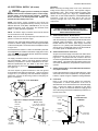
VIII. GAS SUPPLY (gas ovens only)
A. Connection
NOTE: It may be necessary to temporarily remove the rear cool
panels to connect the gas supply.
Check the ovens gas supply requirements before making the
gas utility connection. Gas supply requirements are listed on
the ovens serial plate (Figure 2-16) and in the Gas Orifice and
Pressure Specifications table (Page 4 of this manual).
Check the serial plate to determine the type of gas (Propane or
Natural) to be used with the oven.
Refer to the instructions in the gas hose package (included in
the Installation Kit) before connecting the gas line. One gas line
connection method is shown in Figure 2-18; however,
CAUTION
DURING PRESSURE TESTING NOTE ONE OF THE FOLLOW-
ING:
1. The oven and its individual shutoff valve must be
disconnected from the gas supply piping system during
any pressure testing of that system at test pressure in
excess of 1/2 psi (3.45 kPa).
2. The oven must be isolated from the gas supply piping
system by closing its individual manual shutoff valve
during any pressure testing of the gas supply piping
system at test pressure equal to or less than 1/2 psi (3.45
kPa).
3. If incoming pressure is over 14 W.C. (35mbar), a
separate regulator MUST be installed in the line BEFORE
the individual shutoff valve for the oven.
WARNING: To prevent damage to the control valve
regulator during initial turn- on of gas, it is very important
to open the manual shutoff valve very slowly.
After the initial gas turn-on, the manual shutoff valve
must remain open except during pressure testing as
outlined in the above steps or when necessary during
service maintenance.
compliance with the applicable standards and regulations is
mandatory.
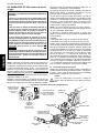
Inlet, regulated, and pilot gas pressure readings can be taken
using a U tube manometer at the tap locations shown in Figure
2-19.
One 90° elbow equals a 7 (2.13m) length of pipe. The
recommended pipe sizes are larger than usually required to
eliminate any operation problems. It is much less expensive
to make the initial installment large enough to do the job rather
than redoing the job later.
NOTE: The installation must conform with local codes or in the
absence of local codes, with the National Fuel Gas Code, ANSI
Z223.1-latest edition.
In Australia, the installation must conform with AGA Code
AG601 and with any requirements of the appropriate statutory
authority.
CANADIAN:
CAN/CGA-B 149.1 Natural Gas Installation Code
CAN/CGA-B 149.2 Propane Installation Code
Certain safety code requirements exist for the installation of gas
ovens; refer to the beginning of Section 2 for a list of the
installation standards. In addition, because the oven is equipped
with casters, the gas line connection shall be made with a
connector that complies with the Standard for Connectors for
Movable Gas Appliances, ANSI Z21.69 (in U.S.A.), or, if appli-
cable, Connectors for Movable Gas Appliances, CAN/CGA-6.16
(in Canada), as well as a quick-disconnect device that complies
with the Standard for Quick-Disconnect Devices for Use With
Gas Fuel, ANSI Z21.41 (in U.S.A.), or, if applicable, Quick-
Disconnect Devices for Use With Gas Fuel, CAN1-6.9 (in
Canada).
B. Gas Conversion
Where permitted by local and national codes, it is possible to
convert ovens from natural to propane gas, or from propane to
natural gas. Use the appropriate Middleby Marshall Gas
Conversion Kit for the specific oven model.
WARNING
All installations, conversions and service work must be
performed by an authorized service agent.
Figure 2-19 - Gas Burner and Piping Assembly
Manual
shutoff valve
Pilot pressure tap
(where pilot gas
pressure is measured)
Combination Gas
Control Valve
(Safety Regulator)
Inlet pressure tap
(where incoming
gas pressure is
measured)
Manifold pressure tap
(where manifold gas
pressure is measured)
On/Off Knob
Always leave in
ON position
Low Flame
Bypass Line
High Flame
Solenoid Valve
Burner Blower
Gas Burner
SECTION 2 - INSTALLATION

13
ENGLISH
SECTION 3 - OPERATION
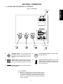
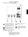
I. LOCATION AND DESCRIPTION OF CONTROLS
Fig. 3-1 - Control Panel
"BLOWER" Switch: Turns the blowers and
cooling fans on and off. The HEAT Switch has no
effect unless the BLOWER Switch is in the ON
position.
A.
"HEAT" Switch: Allows the gas burner to light.
Activation of the gas burner is determined by the
settings on the Digital Temperature Controller.
"CONVEYOR" Switch: Turns the conveyor drive
motor on and off.
B.
C.
D.
E.
Conveyor Speed Controller: Adjusts and dis-
plays the bake time.
Digital Temperature Controller: Continuously
monitors the oven temperature. Settings on the
Digital Temperture Controller control the activa-
tion of the gas burner.
A.
"BLOWER"
(or "
")
switch
E.
Digital Temperature
(or "
")
controller
D.
Conveyor Speed
(or "
")
controller
NOT SHOWN:
F. Machinery Compartment Access Panel Safety Switch:
Disconnects electrical power to the controls and the blow-
ers when the machinery compartment access panel is
opened. The panel should only be opened by authorized
service personnel.
B.
"HEAT"
(or "
")
switch
C.
"CONVEYOR"
(or "
")
switch

14
ENGLISH
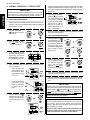
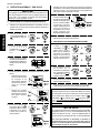
A. DAILY STARTUP PROCEDURE
3. Turn the "CONVEYOR"
(or
) switch to the
ON (or "I") position.
4. If necessary, adjust the
conveyor speed setting
by turning the three
thumbwheels to change
the displayed bake time.
5. Adjust the temperature controller to a desired set tempera-
ture, if necessary.
6. Turn the "HEAT" (or
)
switch to the "ON" (or "I")
position, and wait for the
"HEAT ON" light to turn
on.
8. (Optional) Press the Tem-
perature (
) key to show
the Actual Temperature
in the display, and wait
for the "ACTUAL TEMP"
light to turn on. This al-
lows you to monitor the
oven temperature as it
rises to the setpoint.
1. Turn the "HEAT" (or )
and "BLOWER" (or
)
switches to the "OFF" (or
"O") position. Note that
the blowers will remain
in operation until the oven
has cooled to below
200°F (93°C).
II. NORMAL OPERATION - STEP-BY-STEP
7. Wait for the oven to heat to the setpoint temperature. Higher
setpoint temperatures will require a longer wait. The oven
can reach a temperature of 500°F (232°C) in approximately
5 minutes.
CAUTION
In case of power failure, turn all switches to the OFF (or
"O") position, open the oven window, and remove the
product. After the power has been restored, perform the
normal startup procedure.
The burner will not operate and gas will not flow through
the burner without electric power. No attempt should be
made to operate the oven during a power failure.
3. If the oven is equipped with a window, open the window to
allow the oven to cool faster.
2. Make certain that there
are no products left on
the conveyor inside the
oven. Turn the "CON-
VEYOR" (or
) switch
to the "OFF" (or "O") posi-
tion.
SECTION 3 - OPERATION
2. Turn the "BLOWER" (or
) switch to the ON (or
"I") position.
or
or
mins secs
thumbwheels
+
wait
for
Press the Up Arrow
and Down Arrow
Keys as necessary
to adjust the set-
point.
or
Press the Set Point
and Unlock keys at
the same time. Wait
for the "SET PT" light
to turn on.
or
wait
for
B. DAILY SHUTDOWN PROCEDURE
9. Allow the oven to preheat for 10 minutes after it has reached
the set point temperature.
wait
for
+
+
- - - - - or - - - - -
or
4. After the oven has cooled and the blowers have turned off,
switch the circuit breaker/fused disconnect to the off posi-
tion.
1. Check that the circuit breaker/fused disconnect is in the on
position. If the oven is equipped with a window, check that
the window is closed.
IMPORTANT
Bake time and temperature settings for the oven are preset
at the factory to customer-approved settings. These set-
tings should not be changed during normal operation.
IMPORTANT
On gas ovens, if the "HEAT ON" light will not illuminate, OR
if the oven does not heat, the gas burner may not have lit.
Turn the "HEAT" (
), "BLOWER" ( ), and "CONVEYOR"
(
) switches to the "OFF" ("O") position. Wait for AT
LEAST FIVE MINUTES before restarting the oven. Then,
repeat the Daily Startup procedure.

15
ENGLISH
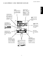
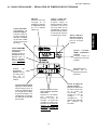
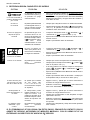
III. QUICK REFERENCE: DIGITAL TEMPERATURE CONTROLLER
Display
Shows the Set Point or
the Actual Tempera-
ture in degrees Fahr-
enheit (F) or Celsius
(C).
"SP LOCK" Light
Lights when the set
point is locked out
from changes. This
setting can only be
changed by service
personnel.
OVERTEMP Light
Lights when the oven
temperature is greater
than 650°F (343°C).
Refer to
Quick Refer-
ence: Troubleshoot-
ing in this section.
Temperature Key
Press this key once to
view the Actual Tem-
perature in the Dis-
play.
Unlock Key
Press this key together
with the Set Point Key
to allow the Set Point
to be changed.
Changes can only be
made for 60 seconds.
Up Arrow and Down Arrow
Keys
Press these keys to adjust
the Set Point up or down. If
the Set Point will not
change, refer to
Set Point
Key and Unlock Key in this
section.
Set Point Key
Press this key together
with the Unlock Key to
allow the Set Point to
be changed.
Changes can only be
made for 60 seconds.
Service Key
For use by ser-
vice personnel
only.
"ACTUAL TEMP"
Light
Lights when the
Actual Tempera-
ture is shown in
the display.
"SET PT" (setpoint)
Light
Lights when the set
point is shown in the
display.
"HEAT ON" Light
Lights when the
burner is in operation.
Note that on all ovens
EXCEPT the
PS360EWB, this light
cycles on and off dur-
ing normal operation.
SECTION 3 - OPERATION

16
ENGLISH
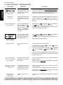
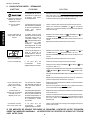
V. QUICK REFERENCE: TROUBLESHOOTING
SYMPTOM PROBLEM SOLUTION
The oven temperature ex-
ceeded 650°F (343°C), and
the burner was automati-
cally shut down.
Follow the procedures under Daily Shutdown Procedures in
this section to shut down the oven. Contact your Middleby
Marshall Authorized Service Agent to determine and correct the
cause of the condition to prevent damage to the oven.
IF THESE STEPS FAIL TO RESOLVE THE PROBLEM, CONTACT YOUR LOCAL MIDDLEBY MARSHALL
AUTHORIZED SERVICE AGENT. A SERVICE AGENCY DIRECTORY IS SUPPLIED WITH YOUR OVEN.
SECTION 3 - OPERATION
light is lit, food product is
undercooked
Oven will not
turn on at all
Oven shuts down shortly
after it is turned on
appears in display,
oven is not heating
Oven will not heat
Oven is operating, but
little or no air is blowing
from air fingers
Conveyor moves with a
jerky motion, or will not
move at all
Food products are
overcooked or
undercooked.
Electrical power may not be
reaching the oven, or the
controls may be set incor-
rectly.
The gas burner did not light
within 90 seconds of turn-
ing the "HEAT" (or
)
Switch to the ON (or "I")
position. This automati-
cally engages a safety lock-
out mode.
The oven did not reach
200°F (93°C) within 15 min-
utes of startup, and the oven
has stopped heating.
Controls may be set incor-
rectly.
Air fingers may have been
reassembled incorrectly
after cleaning.
Conveyor may be jammed
on an object in the oven, or
conveyor belt or drive chain
tension may be incorrect.
Controls may be set incor-
rectly.
Check that the circuit breaker/fused disconnect is turned on.
Check that the "BLOWER"
(or ) Switch is in the ON (or "I")
position. The burner cannot engage until the blowers are in
operation.
Turn the "HEAT" (or
), "BLOWER" (or ), and "CONVEYOR"
(or )switches to the "OFF" (or "O") position.
Wait for AT LEAST FIVE MINUTES before restarting the oven.
Repeat the Daily Startup procedure.
Turn the "HEAT" (or
), "BLOWER" (or ), and "CONVEYOR"
(or )switches to the "OFF" (or "O") position.
Wait for AT LEAST FIVE MINUTES before restarting the oven.
Repeat the Daily Startup procedure.
Check that the Set Point is correctly set.
Check that both the "BLOWER" ( ) and "HEAT" ( ) Switches
are in the ON ("I") position.
If the oven still will not heat,turn the "HEAT" ( ), "BLOWER"
( ), and "CONVEYOR" ( )switches to the "OFF" ("O")
position.
Wait for AT LEAST FIVE MINUTES before restarting the oven.
Repeat the Daily Startup procedure. Check that the Set Point
is above 200°F (93°C).
Turn the oven off, and allow it to cool. Disconnect electrical
power to the oven.
Refer to Section 4,
Maintenance, for instructions on reassem-
bling the air fingers.
Turn the oven off, and allow it to cool. Disconnect electrical
power to the oven.
Check if the conveyor is blocked by an object inside the oven.
Refer to Section 4,
Maintenance, for instructions on checking
the conveyor and drive chain tension.
Check that the set temperature and bake time settings are
correct.

17
ENGLISH
WARNING
Before ANY cleaning or servicing of the oven, perform the following procedure:
1. Switch off the oven and allow it to cool. Do NOT service the oven while it is warm.
2. Turn off the electric supply circuit breaker(s) and disconnect the electric supply to the oven.
3. If it is necessary to move the oven for cleaning or servicing, disconnect the gas supply connection before moving
the oven.
When all cleaning and servicing is complete:
1. If the oven was moved for servicing, return the oven to its original location. For ovens with legs, adjust the legs so
that they are seated properly on the floor. For ovens with casters, lock the front casters.
2. Reconnect the gas supply.
3. Reconnect the electrical supply.
4. Turn on the full-flow gas safety valve. Test the gas line connections for leaks using approved leak test substances
or thick soap suds.
5. Turn on the electric supply circuit breaker(s).
6. Perform the normal startup procedure.
NOTE
ANY replacement parts that require access to the interior of the oven may ONLY be replaced by a Middleby Marshall
Authorized Service Agent.
WARNING
Possibility of injury from moving parts and electrical shock exists in this oven. Switch off and lockout/tagout the electric
supply BEFORE beginning to disassemble, clean, or service any oven. Never disassemble or clean an oven with the
BLOWER switch or any other circuit of the oven switched on.
CAUTION
NEVER use a water hose or pressurized steam-cleaning equipment when cleaning this oven. DO NOT use excessive
amounts of water, to avoid saturating the oven insulation. DO NOT use a caustic oven cleaner, which can damage the
aluminized bake chamber surfaces.
NOTE
It is strongly recommended that the 3-Month, 6-Month, and 12-Month Maintenance procedures in this section be
performed ONLY by a Middleby Marshall Authorized Service Agent.
SECTION 4 - MAINTENANCE

18
ENGLISH
I. MAINTENANCE - DAILY
1. Check that the oven is cool and the power is disconnected,
as described in the warning on Page 17.
2. Clean the outside of the oven with a soft cloth and mild
detergent.
3. Temporarily remove the rear cool panels.
4. Clean ALL of the cooling fan grills and vent openings with
a stiff nylon brush. Refer to Figure 4-1 for the locations of
the grills and vents.
5. Check that ALL cooling fans are operating properly.
Figure 4-1 - Cooling Fan/Vent Locations
CAUTION
If a cooling fan is not operating correctly, it must be replaced
IMMEDIATELY. Operating the oven without adequate cool-
ing can seriously damage the oven's internal components.
6. Replace the rear cool panels.
7. Clean the conveyor belt with a stiff nylon brush. This is
more easily accomplished by allowing the conveyor to
run while you stand at the exit end of the conveyor. Then,
brush the crumbs off the conveyor as it moves.
8. Remove and clean the crumb trays. Be sure to replace
the trays in the same positions from which they were
removed, because they are NOT identical.
SECTION 4 - MAINTENANCE
FRONT
REAR
2 rear fans
Vents in floor
of oven
2 fan grilles in
rear cool panels
Rear cool panels
removed
II. MAINTENANCE - MONTHLY
NOTE: When removing the conveyor, refer to the drawings on
Pages 8-9 in the Installation section.
1. Check that the oven is cool and the power is disconnected,
as described in the warning on Page 17.
2. Remove the drive motor shroud and conveyor extension
covers from the oven.
3. Disconnect the drive chain from the sprocket on the drive
shaft of the conveyor. If two people are available, one
person should lift the idler (right) end of the conveyor as the
second person presses down on the drive (left) end. This
will create enough slack in the chain to remove it.
If this procedure will not free the chain, or if only one person
is available, perform the following steps:
Loosen the two hex head screws that fasten the
conveyor motor's mounting bracket to the oven. See
Figure 2-10 (on Page 9).
Raise the motor to free the chain from the sprocket.
Disconnect the drive chain.
4. Slide the conveyor out of the oven.
NOTE: The conveyor can only be removed from the end of
the oven with the drive motor (left end).
5. Remove the end plugs from the oven. The end plugs are
shown in Figure 1-1, on Page 4 of this Manual.
6. Slide the air fingers and blank plates out of the oven, as
shown in Figure 4-2. AS EACH FINGER OR PLATE IS
REMOVED, WRITE A "LOCATION CODE" ON IT WITH A
MARKER to make sure that it can be reinstalled correctly.
Example of markings:
(Top Row) T1 T2 T3 T4 T5 T6
(Bottom Row) B1 B2 B3 B4 B5 B6
Figure 4-2 - Removing Air Fingers and Plates
Blank PlateAir Finger

19
ENGLISH
Figure 4-3 - Disassembling the Air Fingers
Pull outer plate
straight up
and off
Manifold
Inner plate
Outer Plate
2
Step on lip of manifold
1
Swing ends of inner plate and
manifold apart
3
Pull inner plate
upwards, and
then away from
manifold
4
SECTION 4 - MAINTENANCE
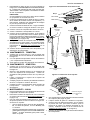
7. Disassemble the air fingers as shown in Figure 4-3. AS
EACH FINGER IS DISASSEMBLED, WRITE THE "LOCA-
TION CODE" FOR THE FINGER ON ALL THREE OF ITS
PIECES. This will help you in correctly reassembling the
air fingers.
CAUTION
Incorrect reassembly of the air fingers will change the
baking properties of the oven.
8. Clean the air finger components and the interior of the
baking chamber using a vacuum cleaner and a damp cloth.
Refer to the boxed warnings on Page 17 for cleaning
precautions.
9. Reassemble the air fingers. Then, replace them in the
oven, using the "location code" as a guide.
10. Replace the end plugs on the oven.
11. Reassemble the conveyor into the oven.
12. Reattach the drive chain. If the motor was repositioned to
allow the chain to be removed, adjust the tension of the
chain to the proper 1/2" (13mm) deflection. Refer to Step
3 of the Conveyor Installation instructions (on Page 9).
13. Check that the conveyor belt has the proper 2-3" (50-75mm)
deflection. If it is necessary to adjust the tension of the belt,
refer to Steps 4-6 of the
Conveyor Installation instructions
(on Page 9).
14. Replace the drive motor shroud and the conveyor extensions.
III. MAINTENANCE - EVERY 3 MONTHS
1. Check that the oven is cool and the power is disconnected,
as described in the warning on Page 17.
2. Vacuum both of the blower motors, and their surrounding
compartments, using a shop vacuum.
3. Tighten all electrical control terminal screws.
IV. MAINTENANCE - EVERY 6 MONTHS
1. Check that the oven is cool and the power is disconnected,
as described in the warning on Page 17.
2. Check for excessive wear on the conveyor drive motor
brushes. The brushes should be replaced if they have worn
to less than 1/4" (6.4mm) in length.
3. Clean and inspect the burner nozzle and electrode assembly.
4. Check (and clean, if necessary) the oven venting system,
including the flue.
5. Check the conveyor drive shaft bushings and spacers.
Replace the components if they are worn.
V. MAINTENANCE - EVERY 12 MONTHS
1. Remove the motor shroud and the drive-end conveyor
extension cover.
2. Disconnect the drive chain as described in Step 3 of the
Monthly Maintenance section (on Page 18).
3. Use a grease gun to lubricate the drive shaft bearings, as
shown in Figure 4-4. When lubricating the bearings:
Use a high-quality NLGI #2, lithium soap grease with
petroleum oil, such as Middleby P/N 17110-0015.
Add the grease slowly until a small bead of grease is
present at the seals. AVOID OVERGREASING.
Excessive greasing may cause harm to the bearing.
4. Manually turn the drive shaft by pulling on the conveyor belt
to purge the grease.
5. Wipe off any excess grease on and around the bearings.
6. Reattach the drive chain. If the motor was repositioned to
allow the chain to be removed, adjust the tension of the
chain to the proper 1/2" (13mm) deflection. Refer to Step
3 of the Conveyor Installation instructions (on Page 9).
7. Replace the motor shroud and conveyor extension cover.
Figure 4-4 - Lubricating the Bearings
Grease fitting
(1 per bearing, 2 total)

ENGLISH FRANÇAIS ESPAÑOL
page 1 page 21 página 41
20
SECTION 4 - MAINTENANCE
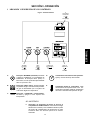
Fig. 4-5 - Key Spare Parts Kit
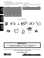
Middleby Cooking Systems Group 1400 Toastmaster Drive Elgin, IL 60120 USA (847)741-3300 FAX (847)741-4406
24-Hour Service Hotline: 1-(800)-238-8444
www.middleby.com
IMPORTANT
An electrical wiring diagram for the oven is located inside the
machinery compartment or control compartment.
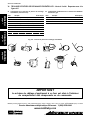
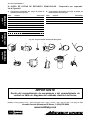
VI. KEY SPARE PARTS KIT - Available separately. See Figure 4-5.
A. Key Spare Parts Kit components (all ovens) B. Additional Key Spare Parts Kit components for gas
ovens
Item Description Part Number
Item Description Part Number
1 1 Kit, Digital Temperature Controller 36939
2 1 Conveyor Drive Motor 27384-0008
3 2 Brushes, Conveyor Drive Motor 22450-0052
4 1 Kit, Conveyor Speed Controller 42810-0133
5 1 Conveyor Control Pickup Assembly 27170-0263
6 1 Kit, Thermocouple 33984
7 1 Cooling Fan 27392-0002
8a 1 Blwr Mtr, 1 Ph, 1/3 HP 27381-0023
8b 1 Blower Motor, 3 Ph, 1/3 HP 27381-0024
9 1 Kit, Ignition Module 42810-0114
10 1 Burner Blower/Motor Assembly 27170-0011
11 1 Solenoid Valve 28091-0017
12 34 5 6
7
89
10
11
Page is loading ...
Page is loading ...
Page is loading ...
Page is loading ...
Page is loading ...
Page is loading ...
Page is loading ...
Page is loading ...
Page is loading ...
Page is loading ...
Page is loading ...
Page is loading ...
Page is loading ...
Page is loading ...
Page is loading ...
Page is loading ...
Page is loading ...
Page is loading ...
Page is loading ...
Page is loading ...
Page is loading ...
Page is loading ...
Page is loading ...
Page is loading ...
Page is loading ...
Page is loading ...
Page is loading ...
Page is loading ...
Page is loading ...
Page is loading ...
Page is loading ...
Page is loading ...
Page is loading ...
Page is loading ...
Page is loading ...
Page is loading ...
Page is loading ...
Page is loading ...
Page is loading ...
Page is loading ...
-
 1
1
-
 2
2
-
 3
3
-
 4
4
-
 5
5
-
 6
6
-
 7
7
-
 8
8
-
 9
9
-
 10
10
-
 11
11
-
 12
12
-
 13
13
-
 14
14
-
 15
15
-
 16
16
-
 17
17
-
 18
18
-
 19
19
-
 20
20
-
 21
21
-
 22
22
-
 23
23
-
 24
24
-
 25
25
-
 26
26
-
 27
27
-
 28
28
-
 29
29
-
 30
30
-
 31
31
-
 32
32
-
 33
33
-
 34
34
-
 35
35
-
 36
36
-
 37
37
-
 38
38
-
 39
39
-
 40
40
-
 41
41
-
 42
42
-
 43
43
-
 44
44
-
 45
45
-
 46
46
-
 47
47
-
 48
48
-
 49
49
-
 50
50
-
 51
51
-
 52
52
-
 53
53
-
 54
54
-
 55
55
-
 56
56
-
 57
57
-
 58
58
-
 59
59
-
 60
60


Ask a question and I''ll find the answer in the document
Finding information in a document is now easier with AI
in other languages
- français: Middleby PS314SBI Manuel utilisateur
- español: Middleby PS314SBI Manual de usuario
Related papers
-
Middleby Marshall PS500 User manual
-
-
Middleby PS220-R68 User manual
-
-
Middleby Marshall PS724-Series User manual
-
-
Middleby Marshall PS540E Installation guide
-
-
-
Other documents
-
-
Toastmaster PS220FS Operating instructions
-
-
-
-
-
-
Leupold PS536GS User manual
-
-