Page is loading ...

©2009 Middleby Marshall Inc.
A MIDDLEBY COMPANY
PS528-Series Gas Ovens: English
owner's
operating
& installation
manual
PS528-Series
OVENS
Model
PS528G
PS528 (Triple)
PS528 (Double)
Part No. 63935 Rev. B
Price $30.00
P: 08/09
PS528 (Single)

ii
WARNING
FOR YOUR SAFETY, DO NOT STORE OR USE
GASOLINE OR OTHER FLAMMABLE VAPORS AND
LIQUIDS IN THE VICINITY OF THIS OR ANY OTHER
APPLIANCE.
WARNING
Improper installation, adjustment, alteration, service,
or maintenance can cause property damage, injury, or
death. Read the installation, operation, and maintenance
instructions thoroughly before installing or servicing
this equipment.
NOTICE
The warranty is NOT VALID unless the oven is installed, started, and
demonstrated under the supervision of a factory-authorized installer.
NOTICE
Contact your authorized Service Agency to perform maintenance and
repairs. A Service Agency Directory is supplied with your oven.
NOTICE
Using any parts other than genuine Middleby Marshall factory-manufactured
parts relieves the manufacturer of all warranty and liability.
NOTICE
Middleby Marshall (Manufacturer) reserves the right to
change specications at any time.
KEEP THIS MANUAL IN A VISIBLE LOCATION NEAR THE OVEN
FOR FUTURE REFERENCE.
NOTICE:
This Owner's Operating and Installation Manual should be given to the user. The operator of the oven should
be familiar with the functions and operation of the oven.
This manual must be kept in a prominent, easily reachable location near the oven.
Ovens are shipped from the factory congured for use with natural gas. If permitted by local, national and
international codes, at the time of installation the oven may be converted to propane gas operation. This
conversion requires the use of at Gas Conversion Kit that is supplied with the oven. For CE-approved ovens,
the conversion is described in the Installation section of this Manual. For domestic and standard export
ovens, instructions are included in the Gas Conversion Kit.
It is suggested to obtain a service contract with a Middleby Marshall Authorized Service Agent.
WARNING
POST, IN A PROMINENT LOCATION, THE EMERGENCY TELEPHONE NUMBER OF YOUR LOCAL
GAS SUPPLIER AND INSTRUCTIONS TO BE FOLLOWED IN THE EVENT YOU SMELL GAS.
Instructions to be followed in the event the user smells gas shall be obtained by consulting the local gas
supplier. If the smell of gas is detected, immediately call the emergency phone number of your local Gas
Company. They will have personnel and provisions available to correct the problem.

iii
MIDDLEBY MARSHALL INC.
OVEN LIMITED WARRANTY
(Non U.S.A.)
The Seller warrants equipment manufactured by it to be free from
defects in material and workmanship for which it is responsible. The
Seller’s obligation under this warranty shall be limited to replacing or
repairing, at Seller’s option, without charge, F.O.B. Seller’s factory,
any part found to be defective and any labor and material expense
incurred by Seller in repairing or replacing such part. Such warranty
is limited to a period of one year from date of original installation or
15 months from date of shipment from Seller’s factory, whichever
is earlier, provided that terms of payment have been fully met. All
labor shall be performed during regular working hours. Overtime
premium will be charged to the Buyer.
This warranty is not valid unless equipment is installed,
started, and demonstrated under the supervision of a factory-
authorized installer.
Normal maintenance functions, including lubrication, adjustment of
airow, thermostats, door mechanisms, microswitches, burners and
pilot burners, and replacement of light bulbs, fuses and indicating
lights, are not covered by warranty.
Any repairs or replacements of defective parts shall be performed by
Seller’s authorized service personnel. Seller shall not be responsible
for any costs incurred if the work is performed by other than Seller’s
authorized service personnel.
When returning any part under warranty, the part must be intact and
complete, without evidence of misuse or abuse, freight prepaid.
Seller shall not be liable for consequential damages of any kind
which occur during the course of installation of equipment, or which
result from the use or misuse by Buyer, its employees or others of
the equipment supplied hereunder, and Buyer’s sole and exclusive
remedy against Seller for any breach of the foregoing warranty or
otherwise shall be for the repair or replacement of the equipment
or parts thereof affected by such breach.
The foregoing warranty shall be valid and binding upon Seller if and
only if Buyer loads, operates and maintains the equipment supplied
hereunder in accordance with the instruction manual provided to
Buyer. Seller does not guarantee the process of manufacture by
Buyer or the quality of product to be produced by the equipment
supplied hereunder and Seller shall not be liable for any prospective
or lost prots of Buyer.
THE FOREGOING WARRANTY IS EXCLUSIVE AND IN LIEU
OF ALL OTHER EXPRESS AND IMPLIED WARRANTIES
WHATSOEVER. SPECIFICALLY THERE ARE NO IMPLIED
WARRANTIES OF MERCHANTABILITY OR OF FITNESS FOR
A PARTICULAR PURPOSE.
The foregoing shall be Seller’s sole and exclusive obligation and
Buyer’s sole and exclusive remedy for any action, whether in breach
of contract or negligence. In no event shall seller be liable for a sum
in excess of the purchase price of the item.
Model No.
Modéle No.
Serial No.
Serié No.
Installation Date
Date d'installation
MIDDLEBY MARSHALL
No Qu i b b l e li m i t e d Wa r r a N t y
(U.S.A. On l y )
MIDDLEBY MARSHALL, HEREINAFTER REFERRED
TO AS “THE SELLER”, WARRANTS EQUIPMENT
MANUFACTURED BY IT TO BE FREE FROM DEFECTS
IN MATERIAL AND WORKMANSHIP FOR WHICH IT IS
RESPONSIBLE. THE SELLER’S OBLIGATION UNDER
THIS WARRANTY SHALL BE LIMITED TO REPLACING
OR REPAIRING, AT SELLER’S OPTION, WITHOUT
CHARGE, ANY PART FOUND TO BE DEFECTIVE AND
ANY LABOR AND MATERIAL EXPENSE INCURRED BY
SELLER IN REPAIRING OR REPLACING SUCH PART.
SUCH WARRANTY SHALL BE LIMITED TO THE ORIGINAL
PURCHASER ONLY AND SHALL BE EFFECTIVE FOR
A PERIOD OF ONE YEAR FROM DATE OF ORIGINAL
INSTALLATION, OR 18 MONTHS FROM DATE OF
PURCHASE, WHICHEVER IS EARLIER, PROVIDED THAT
TERMS OF PAYMENT HAVE BEEN FULLY MET.
This warranty is valid only if the equipment is installed,
started, and demonstrated under the supervision of a factory-
authorized installer.
Normal maintenance functions, including lubrication,
cleaning, or customer abuse, are not covered by this no
quibble warranty.
Seller shall be responsible only for repairs or replacements
of defective parts performed by Seller’s authorized service
personnel. Authorized service agencies are located in
principal cities throughout the contiguous United States,
Alaska, and Hawaii. This warranty is valid in the 50 United
States and is void elsewhere unless the product is purchased
through Middleby International with warranty included.
The foregoing warranty is exclusive and in lieu of all
other warranties, expressed or implied. There are no
implied warranties of merchantability or of tness for a
particular purpose.
The foregoing shall be Seller’s sole and exclusive obligation
and Buyer’s sole and exclusive remedy for any action,
including breach of contract or negligence. In no event shall
Seller be liable for a sum in excess of the purchase price of
the item. Seller shall not be liable for any prospective or lost
prots of Buyer.
This warranty is effective on Middleby Marshall
equipment sold on, or after, February 15, 1995.
© 2009 - Middleby Marshall, A Middleby Company.
The Middleby Marshall logo is a registered trademark of Middleby Marshall, A Middleby Company.
Middleby Marshall Inc. • 1400 Toastmaster Drive • Elgin, Illinois 60120-9272 U.S.A. • (847) 741-3300 • FAX: (847) 741 4406

iv
NOTE
Wiring Diagrams are in Section 6 of this Manual.
The diagram for each oven is also on the lower
inner surface of its Control Console.
TABLE OF CONTENTS
Page
SECTION 1
I. MODEL IDENTIFICATION ..............................................1
SERIES PS528 GAS SPECIFICATIONS .............................2
II. COMPONENT FUNCTION .............................................4
A. Conveyor Motor and Conveyor Belt ........................4
B. Blower Fan .................................................................4
C. Gas Burner .................................................................4
D. Cooling Fan ................................................................4
E. Air Fingers and Blank Plates - See Figure 1-9 ........4
SECTION 2
I. UNLOADING ....................................................................8
PARTS LIST FOR SERIES PS528 GAS OVEN
INSTALLATION KIT .....................................................8
UTILITY ROUGH-IN DIMENSIONS AND POSITIONING
FOR PS528-SERIES OVENS .....................................13
CIRCUIT BREAKER .......................................................13
ELECTRICAL SPECIFICATIONS ..................................13
ELECTRICAL RATING ...................................................13
SUPPLY WIRE ...............................................................13
SUGGESTED ..................................................................13
II. VENTILATION GUIDELINES .........................................13
III. ELECTRICAL CONNECTION INFORMATION FOR
PS528-SERIES OVENS. .............................................14
IV. ELECTRIC SUPPLY FOR GAS HEATED OVENS ......14
V. GAS SUPPLY ...............................................................15
SECTION 3 INSTALLATION
I. CONTROL FUNCTIONS .................................................19
II. COMPONENT INFORMATION AND LOCATION ........20
A. Door Safety Switch ..................................................20
B. Blower Switch ..........................................................20
C. Heat Switch ..............................................................20
D. Temperature Controller ............................................20
E. Conveyor .................................................................21
MEASURING CONVEYOR SPEED. ..............................21
TABLE OF CONTENTS
(Continued)
Page
III. STEP-BY-STEP OPERATION ........................................22
A. Startup Procedures ..................................................22
Daily Startup ..................................................................22
Power Failure .................................................................22
B. Shutdown Procedure ..............................................22
IV. NORMAL OPERATION - STEP-BY-STEP ................... 24
A.Daily Startup Procedure ............................................ 24
B. Daily Shutdown Procedure ..................................... 24
V. QUICK REFERENCE: TROUBLESHOOTING ............ 26
SECTION 4 MAINTENANCE
I. MAINTENANCE - DAILY ............................................. 28
A. Exterior ...................................................................... 28
B. Cooling Fan ............................................................... 28
C. Conveyor Belt ........................................................ 28
D. Crumb Pans ............................................................ 28
II. MAINTENANCE - MONTHLY ...................................... 29
A. Removing Conveyor From Oven For Cleaning .... 29
B. Air Fingers Disassembly For Cleaning .................. 31
C. Reassembly of Air Fingers ..................................... 32
D. Reinstall End Plugs ................................................. 35
E. Conveyor Reassembly Into Oven ........................... 36
F. Checking Conveyor Belt Tension ........................... 36
G. Conveyor Belt Link Removal .................................. 37
H. Attaching Drive Chain ............................................. 38
III. MAINTENANCE - EVERY 3 MONTHS ......................... 39
A. Electrical Terminals ................................................. 39
B. Ventilation ................................................................ 39
IV. MAINTENANCE - EVERY 6 MONTHS ......................... 39
PS528-SERIES GAS OVEN KEY SPARE
PARTS ...................................................................... 40
KEY SPARE PARTS KIT ............................................... 40
SECTION 5 TROUBLESHOOTING
Troubleshooting Charts ...................................................... 41
SECTION 6 ELECTRICAL SCHEMATICS
Wiring Diagram, G208-240V 50/60 GO, PS528 ............... 43

SECTION 1
DESCRIPTION
1
I. MODEL IDENTIFICATION
The Middleby Marshall PS528-Series may be used
either as a single oven or stacked for use as double or
triple ovens.
A single PS528-Series Oven (Figure 1-1) is mounted on a
base pad with legs. A double oven (Figure 1-2) consists
of two, stacked, single ovens. A triple oven (Figure 1-3)
consists of three stacked single ovens. The lower oven
is mounted on a base pad with stacking pins.
On a double or triple oven, the ovens operate indepen-
dently. All ovens use identical controls and components.
One oven can be cleaned or serviced, while the others
are operating.
SECTION 1
DESCRIPTION
Figure 1-1. Single PS528 Oven
Figure 1-2. Double PS528 Oven
Figure 1-3. Triple PS528 Oven

2
SECTION 1
DESCRIPTION
PS528 SERIES OVEN SPECIFICATIONS
Conveyor Belt Width 18.00" (457mm)
Heating Zone Length 28.00" (711mm)
Baking Area Square Feet 3.5 sq. ft. (0.33 sq. m.)
Overall Dimension
Standard Single Oven w/Legs 50.00" (1270mm) L ×
40.75" (1035mm) W ×
21.72" (786mm) H ×
Overall Dimension
Double Oven 50.00" (1270mm) L ×
40.75" (1035mm) W ×
37.27" (947mm) H x
Overall Dimension
Triple Oven 50.00" (1270mm) L x
40.75" (1035mm) W ×
52.82" (1342mm) H ×
Weight of Single Oven 250 lb (93.3kg)
Shipping Weight 325 lb (121.3kg)
Shipping Cube 22.1 ft
3
(0.62 m
3
)
BTU's - Natural or Propane Gas 50,000 BTU/hr
Gas Input - Natural or Propane Gas 1/2" NPT
Maximum Operating Temperature 600°F (316°C)
Warm-up Time 20 min.
Belt Speed Limits 1-10 minutes
SERIES PS528 ELECTRICAL SPECIFICATIONS
Main Blower & Control Circuit Phase Frequency Amperage Poles Wires
Elements Voltage Voltage Draw
208-240V 208-240V 1 Ph 50/60 Hz 1.5 Amp 2 Pole 3 Wire
(2 hot, 1 grd)
GAS ORIFICE AND PRESSURE SPECIFICATIONS (PER OVEN CAVITY) - CE OVENS
Supply (Inlet) Pressure
IT,PT,ES,SE,
Main UK,CH,IT,AT, SE,CH,AT,DK, BE,IE,IT,PT, Orice Rated
Gas Orice DK,FI DE BE,FR FI,DE,NL ES,UK (Manifold) Heat
Type dia.
I
2H
I
2E
I
2E+
I
3B/P
I
3+
Pressure Input
G20 2.3749 20 20 20 -- -- 11.21 22.36
mm mbar mbar mbar mbar kW-hr.
G25 2.3749 -- -- -- -- -- 16.19 22.36
mm mbar kW-hr.
G30 1.3970 -- -- -- 29 or 50 28-30, 37 26.2 22.59
mm mbar or 50 mbar mbar kW-hr.
GAS ORIFICE AND PRESSURE SPECIFICATIONS (PER OVEN CAVITY) - DOMESTIC AND STANDARD EXPORT OVENS
Orice (Manifold)
Gas Type Main Orice I.D. Supply (Inlet) Pressure Pressure
Natural #42 drill (.094")(2.38mm) 6-8” W.C. (14.9-19.9mbar) * 3.5” W.C. (8.72mbar)
Propane #48 drill (.076")(1.93mm) 6-8” W.C. (14.9-19.9mbar) * 3.5” W.C. (8.72mbar)
* The gas supply pressures and orice sizes shown are for ovens installed in North America. The required gas supply pressures and orice sizes
of ovens installed in other locations are dependent on the local gas type and on all applicable local codes.
NOTE
Wiring Diagrams are contained in Section 6 of this Manual
and are also located inside the oven at the
bottom of the Control Panel.
Additional electrical information is provided on the oven's serial plate.
This Manual Must Be Kept For Future Reference.

SECTION 1
DESCRIPTION
3
II. COMPONENT FUNCTION (Figure 1-4)
Figure 1-4. PS528-Series Oven Components Locations

4
SECTION 1
DESCRIPTION
II. COMPONENT FUNCTION
A. Conveyor Motor and Conveyor Belt
The conveyor belt is driven by a variable-speed electric
motor (Figure 1-5) operating through a gear reducer.
The motor speed is controlled by a digital control. The
stainless-steel wire belt can travel in either direction at
variable rates ranging from 3 minutes to 30 minutes;
this is the time that a product can take to pass through
the oven.
B. Blower Fan
The blower fans are located at the rear of the oven.
These blowers force heated air through the air ngers.
The BLOWER switch must be set to “ON” or “I” for oven
warmup and baking.
C. Gas Burner
The gas burner is located inside the rear panel and is
controlled by the temperature controller.
D. Cooling Fan — See Figure 1-5 and Figure 1-6
The cooling fan is located in the back of the oven.
The cooling fan draws air through its grille, blowing it
through the blower motor compartment and the control
compartments into the oven top and exhausted out the
front louvers.
E. Air Fingers and Blank Plates - See Figure 1-7
E1. Air Fingers
An Air Finger Assembly is made up of three parts:
1. Outer Plate - The Outer Plate is the removable cover-
ing with tapered holes, which direct the air stream onto
the product being baked.
2. Inner Plate -The perforated Inner Plate is vital in
forming the unique air jets. It must be assembled into
the manifold with its holes aligned with the holes of the
outer plate.
3. Manifold - The Manifold is the assembly which slides
on tracks into the oven plenum.
Figure 1-5. Machinery Compartment
Components
Blower Assembly
Right Control Box

SECTION 1
DESCRIPTION
5
Figure 1-6. Cooling Fan

6
SECTION 1
DESCRIPTION
Figure 1-7. Blank Plates (two sizes) and an Air Finger.
F2. Blank Plates
1. Blank Plates- The Blank Plates are available to install
on the plenum where an air nger is not required.

SECTION 2
INSTALLATION
7
WARNING
Keep the appliance area free and clear of combustibles.
WARNING
Do not obstruct the ow of combustion and ventilation air to and from your oven. There must be no
obstructions around or underneath the oven. Constructional changes to the area where the oven is
installed shall not affect the air supply to the oven.
CAUTION
For additional installation information, contact your local Authorized Service Agent.
NOTE
There must be adequate clearance between the oven and combustible construction. Clearance must
also be provided for servicing and for proper operation.
NOTE
An electrical wiring diagram for the oven is located inside the machinery compartment.
WARNING
The oven must be installed on an even (level) non-ammable ooring and any adjacent walls must be
non-ammable. Recommended minimum clearances are specied in the Description section of this
Manual.
WARNING - For gas ovens, after any conversions, readjustments, or service work on the oven:
• Perform a gas leak test.
• Test for correct air supply.
• Test for proper combustion and gas supply.
• Check that the ventilation system is in operation.
NOTE
In Australia, the oven installation must conform with any requirements of the appropriate statutory authority.
Gas oven installtions must conform with AGA Codes AG311 and AG601.
NOTE
In Canada, the oven installation must conform with local codes. In the absence of local codes, gas oven
installations must conform with the Natural Gas Installation Code, CAN/CGA-B149.1, or the Propane
Gas Installation Code, CAN/CGA-B149.2, as applicable. Installed ovens must be electrically grounded in
accordance with local codes, or in the absence of local codes, with the Canadian Electrical Code CSA C22.2.
NOTE
In the USA, the oven installation must conform with local codes. In the absence of local codes, gas
oven installations must conform with the National Fuel Gas Code, ANSI Z223.1. Installed ovens must be
electrically grounded in accordance with local codes, or in the absence of local codes, with the National
Electrical Code (NEC), or ANSI/NFPA70.
NOTE
All aspects of the oven installation, including placement, utility connections, and ventilation requirements,
must conform with any applicable local, national, or international codes. These codes supersede the
requirements and guidelines provided in this manual.
NOTE
In CE countries, all aspects of the gas supply connection must comply with current IEC/CEE requirements and with
all applicable local, national, and international codes. In addition, four casters are provided to allow the oven to be
more easily moved to the installation location. These casters are intended to simplify pre-installation movement
only, and are NOT suitable for use as part of a CE oven installation. During the installation procedure, the casters
MUST be removed, so that the oven can be supported by the supplied 152mm adjustable legs.
SECTION 2
INSTALLATION

8
SECTION 2
INSTALLATION
PARTS LIST FOR SERIES PS528 GAS OVEN
INSTALLATION KIT
Single Stack Oven
P/N 63946
ITEM
NO. QTY PART NO. DESCRIPTION
1 4 3101908 LEG 4″ AD FT
2 1 62208 INSULATION BOTTOM TRAY
3 1 62206 BOTTOM TRAY WELDMENT
4 1 61650 TOP COVER
5 4 51387 SCREW MSSLT THREAD 8-32 × 1/2, 18-8
7 1 22450-0228 GAS HOSE RESTRAINT CABLE
8 1 22361-0001 GAS HOSE
9 1 49975 CORD & PLUG NEMA L6-20P
10 1 23115-0009 MANUAL GAS VALVE, 3/4″ × 1/2, COUPLER
11 1 31823 REDUCER,3/4″–1/2″
12 4 62207 INSULATION
NOTE: The oven, when installed, must be electrically
grounded in accordance with local codes, or in the absence
of local codes, with the National Electrical Code (NEC),
or ANSI/NFPA70.
NOTE
There must be adequate clearance between
the oven and any adjacent combustible con-
struction. Clearance must also be provided
for servicing and for operation.
CAUTION
It is recommended that the oven be placed under
a ventilation hood for adequate air supply and
ventilation.
CAUTION
Do not obstruct the ow of ventilation air to and
from your oven. Do not obstruct the fan holes in
the rear of the unit.
I. UNLOADING
Your Middleby Marshall PS528-Series Oven is shipped
partially assembled. It will arrive in a carton on a crate.
The crate and carton must be examined before signing the
Bill of Lading. Report any visible damage to the transport
company, and check for the proper number of crates. If
apparent damage is found, make arrangements to le a
claim against the carrier. Surface Interstate Commerce
Regulations (U.S.A.) require that the claim must be initi-
ated by the consignee within 10 days from the date that
the shipment is received.
7
8
Figure 2-1. PS528-Series Gas Oven Installation Parts
9
10
11

SECTION 2
INSTALLATION
9
Figure 2-1 (continued). PS528-Series Gas Oven Installation Parts
ITEM NO. QTY PART NO. DESCRIPTION
1 2 62208 INSULATION BOTTOM TRAY
2 1 62206 BOTTOM TRAY WELDMENT
3 1 61650 TOP COVER
4 4 51387 SCREW MSSLT THREAD 8-32 × 1/2, 18-8
5 4 M3828 PIN, ALIGNMENT
7 1 22450-0228 GAS HOSE RESTRAINT CABLE
8 3 22361-0001 GAS HOSE
9 1 49975 CORD & PLUG NEMA L6-20P
10 1 23115-0009 MANUAL GAS VALVE, 3/4″ × 1/2, COUPLER
11 1 31823 REDUCER, 3/4″–1/2″
12 2 59227 HEAT GUARD
13 4 62207 INSULATION
PARTS LIST FOR SERIES PS528 Gas OVEN
INSTALLATION KIT Triple Stack Oven P/N 63948
7
8
ITEM NO. QTY PART NO. DESCRIPTION
1 2 62208 INSULATION BOTTOM TRAY
2 1 62206 BOTTOM TRAY WELDMENT
3 1 61650 TOP COVER
4 4 51387 SCREW MSSLT THREAD 8-32 × 1/2, 18-8
5 4 3101908 LEG 4″ AD FT
7 1 22450-0228 GAS HOSE RESTRAINT CABLE
8 2 22361-0001 GAS HOSE
9 1 49975 CORD & PLUG NEMA L6-20P
10 1 23115-0009 MANUAL GAS VALVE, 3/4″ × 1/2, COUPLER
11 1 31823 REDUCER, 3/4″–1/2″
12 1 59227 HEAT GUARD
13 4 62207 INSULATION
PARTS LIST FOR SERIES PS528 Gas OVEN
INSTALLATION KIT Double Stack Oven P/N 63947
7
8
9
9
11
10
11
10

10
SECTION 2
INSTALLATION
Figure 2-5. MODEL PS528 SINGLE OVEN DIMENSIONS
The Opening Height is Adjustable from 2-1/4 inch minimum
to 3-3/4 inch maximum in 1/2 inch increments.
1
1

SECTION 2
INSTALLATION
11
Figure 2-6. MODEL PS528 DOUBLE OVEN DIMENSIONS
1
The Opening Height is Adjustable from 2-1/4 inch mini-
mum to 3-3/4 inch maximum in 1/2 inch increments.
P/N 59927 is shown in its correct installed position.
1
2

12
SECTION 2
INSTALLATION
Figure 2-7. MODEL 528 TRIPLE OVEN DIMENSIONS
1
The Opening Height is Adjustable from 2-1/4 inch mini-
mum to 3-3/4 inch maximum in 1/2 inch increments.
P/N 59927 is shown in its correct installed position.
1
2

SECTION 2
INSTALLATION
13
WARNING
DO NOT USE CONDUIT OR GAS LINE
FOR GROUND CONNECTION.
CAUTION
IT IS RECOMMENDED THAT THE OVEN
BE PLACED UNDER A VENTILATION
HOOD FOR ADEQUATE AIR SUPPLY
AND VENTILATION.
ELECTRIC SUPPLY TO BE
PROVIDED BY CUSTOMER
CIRCUIT BREAKER
Separate circuit breaker with lockout/tagout electrical
shutoff for each oven. Wire each oven separately.
15A Amp circuit breaker for 208-240V.
ELECTRICAL SPECIFICATIONS
DOMESTIC: 208V main blower motors, 1 Ph, 1.5 Amp
draw, 50/60 Hz, 208-240V control circuit, 2 pole, 3 wire
system per oven (2 hot, 1 grd).
Do NOT use conduit for ground.
or
DOMESTIC or EXPORT: 240V main blower motors, 1
Ph, 1.5 Amp draw, 50/60 Hz, 208-240V control circuit, 2
pole, 3 wire system per oven (2 hot, 1 grd).
230V main blower motors, 1 Ph, 1.5 Amp draw, 50/60 Hz,
208-240V control circuit, 2 pole, 3 wire system per oven
(2 hot, 1 grd).
Do NOT use conduit for ground.
A 6 foot cord with a NEMA L6-20 plug is supplied on
Domestic units.
POWER RATING
50,000 BTU/hr (14.7 kW/hr.)
SUPPLY WIRE
Supply wire size must be in accordance with the National
Electrical Code (current edition) and must be in compli-
ance with local codes.
SUGGESTED
If space permits, service should be located near the
control console end of the oven(s) to allow convenient
access to safety switches.
UTILITY ROUGH-IN DIMENSIONS AND POSITIONING
FOR PS528-SERIES OVENS
CAUTION
UNIT MUST HAVE AIR VENT PLATES
INSTALLED OR WARRANTY WILL BE VOID.
II. VENTILATION GUIDELINES
A mechanically driven ventilation system is required for
the PS528 Series Middleby Marshall conveyorized gas
ovens.
Local codes and conditions vary greatly from one area
to another and must be complied with. Following are
the suggested requirements for good ventilation. Please
remember these are recommendations or guidelines, you
may have a special condition or problem that will require
the services of a ventilation engineer or specialist. Proper
ventilation is the oven owner’s responsibility. Improper
ventilation can inhibit oven performance.
Please Note: There are now two “stand off” ‘C’ Chan-
nels and “Heat Guards” for “Double and Triple Ovens”
that must be installed in the eld.
Please Note: There is now one heat guard on dou-
ble units and two heat guards on triple units. See
Figure 2-7.
These ‘C’ Channel brackets are installed in the vertical
plane using existing screws (Item 6) to support these ‘C’
Channels using the upper and lower Key Hole openings
in the ‘C’ Channels. The ‘C’ Channels are identical and
once installed will allow ample amounts of air through
the cooling fan mounted on the rear side of the oven by
keeping the oven away from the rear wall.
Figure 2-9. Typical PS528-Series Oven(s)
Installation

14
SECTION 2
INSTALLATION
III. ELECTRICAL CONNECTION
INFORMATION FOR PS528-SERIES
OVENS.
WARNING
Authorized supplier personnel normally accom-
plish the connections for the ventilation system,
electric and gas supplies, as arranged by the
customer. Following these connections, the
factory-authorized installer can perform the initial
startup of the oven.
Check the oven data plate (Figure 2-10) before making
any electric supply connections. Electric supply connec-
tions must agree with data on the oven data plate.
NOTE: The electric supply installation must satisfy the
requirements of the appropriate statutory authority, such
as the National Electrical Code (NEC), ANSI/NFPA70,
(U.S.A.); the Canadian Electrical Code, CSA C22.2;
the Australian Code AG601; or other applicable regula-
tions.
A fused disconnect switch or a main circuit breaker
(customer furnished) MUST be installed in the electric
supply line for each oven; it is recommended that this
switch/ circuit breaker have lockout/tagout capability. The
electric supply connection must meet all national and local
electrical code requirements. Copper is the recommended
material for the electrical supply conductors.
IV. ELECTRIC SUPPLY FOR GAS HEATED
OVENS
Power requirements for gas heated ovens are 208 -
240VAC, 1-phase, 3-wire (2 ‘hot’, 1 ground). Electrical
connection is made through a cord and plug. Using
exible cable(s) for the electrical power supply conductors
requires a 2″ (51mm) strain-relief tting (not furnished)
to enable safe access to the terminal block from which
oven power is distributed.
The supply conductors must be of the size and material
(copper) recommended to provide the current required;
(refer to the data plate for the ampere specications).
The electric current rating for each conductor supplying
a PS528-Series Oven is 1.5A.
Figure 2-11. Junction Connection Box
Figure 2-10. Typical Electric Oven Data Plate
ELECTRICAL
INLET
GAS INLET

SECTION 2
INSTALLATION
15
V. GAS SUPPLY
CAUTION
DURING PRESSURE TESTING NOTE THE FOLLOWING:
1. The oven and its individual shutoff valve must be dis-
connected from the gas supply piping system during any
pressure testing of that system at test pressure in excess
of 1/2 psi (3.45 kPa).
2. The oven must be isolated from the gas supply piping
system by closing its individual manual shutoff valve dur-
ing any pressure testing of the gas supply piping system
at test pressure equal to or less than 1/2 psi (3.45 kPa).
3. If incoming pressure is over 14" W.C. (35mbar), a sepa-
rate regulator MUST be installed in the line BEFORE the
individual shutoff valve for the oven.
WARNING: To prevent damage to the control valve regu-
lator during initial turn- on of gas, it is very important to
open the manual shutoff valve very slowly.
After the initial gas turn-on, the manual shutoff valve must
remain open except during pressure testing as outlined
in the above steps or when necessary during service
maintenance.
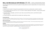
A. Gas Utility Rough-In Recommendations
The following gas system specifications are STRONGLY
RECOMMENDED. Deviating from these recommendations may
affect the baking performance of the oven.
Gas Meter - 650 cfh (307
/min) meter
Gas Line
• DEDICATEDLINEfromthegasmetertotheoven
• 1-1/2"(38.1mm)pipefornaturalgas
• 1-1/2"(38.1mm)pipeforpropane
• Maximumlength: 200' (61m). Each 90° elbowequals 7'
(2.13m) of pipe.
Figure 2-15 - Flexible Gas Hose Installation
B. Gas Conversion
Where permitted by local and national codes, it is possible to
convert ovens from natural to propane gas, or from propane to
natural gas. Use the appropriate Middleby Gas Conversion Kit
forthespecicovenmodel.
CAUTION: The terms of the oven’s warranty require all start-
ups, conversions and service work to be performed
by a Middleby Authorized Service Agent.
C. PS528 Propane Conversion
Twoitemshavetobechanged,tochangetheoventoLP:
1. Replacemainorices.
2. Adjust main gas regulator per instructions below.
Disconnect the manifold union closest to the main burner, and
remove the manifold assembly (four screws). Slide out the manifold
assembly (leaving the ignition and sense wires connected).
Replacethemainorices.
Replacethemainoricesonthemanifoldassemblieswiththe
LP units, and replace the manifold assembly. Reconnect the
union.
D. Adjusting the Maximum Pressure Setting
1. Disconnect pressure feedback connection (if applicable).
2. Connect a suitable pressure gauge to pipe line or to outlet
pressure tap of gas control concerned, to measure burner
pressure (measuring point must be as near to burner as
possible).
3. Make sure that the appliance is in operation and the Moduplus
®
coilisenergizedwithmaximumcurrent.
4. Ifmaximumratepressureneedsadjustment,usean8mm
wrenchtoturnadjustmentscrewformaximumpressuresetting
(clockwise to increase or counter-clockwise to decrease
pressure), until the desired maximum outlet pressure is
obtained.
5. Disconnect electrical connection of the Moduplus
®
.
6. Check minimum pressure setting and readjust if necessary.
(See Adjusting Minimum Pressure Setting for proper adjusting
procedure.)
7. Reconnect pressure feedback connection (if applicable).
8. If minimum and maximum pressures are set, wire the
Moduplus
®
in circuit.
9. Close pressure tap screw.
E. Adjusting the Minimum Pressure Setting
1. Disconnect pressure feedback connection (if appcable).
2. Connect a suitable pressure gauge to pipe line or to outlet
pressure tap of gas control concerned, to measure burner
pressure (measuring point must be as near to burner as
possible).
3. Disconnect electrical connection of the Moduplus
®
.
4. Energize operator, set control in operation and wait until an
outlet pressure is recorded on pressure gauge.
5. If minimum rate pressure needs adjustment, use an 8 mm
wrench to turn adjustment screw for minimum pressure setting
(clockwise to increase or counter-clockwise to decrease
pressure), until the desired minimum outlet pressure is
obtained.
6. Check if main burner lights easily and reliable at minimum
pressure.
7. Reconnect pressure feedback connection (if applicable).
8. Close pressure tap screw.
To Gas
Supply
Pipe
90°
Elbow
Quick-
disconnect
device
Flexible
Gas Hose
Full-Flow
Gas
Shutoff
Valve
3/4" gas
pipe nipple
3/4"-1/2"
gas pipe
reducer
Individual gas
connection
for each oven
cavity
1/2" gas
pipe nipple
1/2" gas
line tee with
pressure tap

16
SECTION 2
INSTALLATION
=
G. Maintenance
It is recommended to check yearly the minimum and the
maximumsettingandreadjustthemifnecessary.
H. Connection
WARNING
Some procedures in this section may require
conversions, readjustments, or service on the
oven's gas system. Before performing these
procedures, check that the main gas supply valve and
the circuit breaker/fused disconnect are in the OFF ("O")
position. After completing these procedures, perform a
gas leak test before operating the oven.
CAUTION
The terms of the oven's warranty require all start-ups, conver-
sions and service work to be performed by a Middleby Mar-
shall Authorized Service Agent. The installation, start-up and
changes required when changing from one gas type to another
can be performed ONLY by a certied professional.
NOTE:
Certainsafetycoderequirementsexistfortheinstallation
of gas ovens; refer to the beginning of Section 2 for a list of
theinstallationstandards.Inaddition:
• In the USA, the installation must conform with local codes,
or in the absence of local codes, with the National Fuel
Gas Code, ANSI Z223.1.
• In Canada, the installation must conform with local codes,
or in the absence of local codes, with the Natural Gas
Installation Code, CAN/CGA-B 149.1, or the Propane
Installation Code, CAN/CGA-B 149.2, as applicable.
• In Australia, the installation must conform with AGA Codes
AG311 andAG601, and with any requirements of the
appropriate statutory authority.
• In CE countries, the gas supply connection should be
according to EN-203 (gas appliance directive) and to
applicable ISO 228-1 or ISO 7-1 recommendations. All
aspects of the gas supply connection must comply with
current IEC/CEE requirements and with all applicable
local, national, and international codes.
• For all ovens equipped with casters, the gas line connection
shallbemadewith:
- A connector that complies with the Standard for
Connectors for Movable Gas Appliances, ANSI Z21.69
(in USA), or Connectors for Movable Gas Appliances,
CAN/CGA-6.16 (in Canada).
Checktheoven’sgassupplyrequirementstodeterminethe
typeofgastobeusedwiththeoven.Ifthegastyperequired
doesNOTmatchthelocalsupply:
• For North American installations, a conversion kit is
supplied with the oven to allow operation using propane
gas. Refer to Part B, Gas Conversion, in this section.
• ForCEovens,directionsforconvertingtheovenforuse
with other gases are described in Part D.1, Preparation
for Use with Various Gases, in this section.
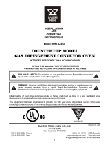
Figure 2-16. Gas Burner Assembly
Figure 2-17. Burner Assembly
Figure 2-18. Gas Valve
F. Checkout
After any adjustment, set appliance in operation and observe
through a component cycle to ensure that burner system
components function correctly.
Gas Burner
Manifold Pressure Tap
Manifold Pressure Tap
Gas Valve
Gas Burner
Assembly
MainOrices
Adjustment Screw (5 mm)
for minimum pressure
setting
Adjustment
Screw (8 mm) for
maximum
pressure
setting
/