
Instruction manual
Manuel d'instructions
Manual de instrucciones
513
517
N384541 MAY2014 Copyright © 2006 2014 PORTER-CABLE
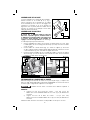
LOCK MORTISER
AND LOCK FACE
TEMPLATE
MORTAISEUSE DE
SERRURE
ET GABARIT DE FACE DE
SERRURE
ESCOPLEADORA Y
PLANTILLA PARA
CERRADURAS DE PUERTA
www.portercable.com
INSTRUCTIVO DE OPERACIÓN, CENTROS
DE SERVICIO Y PÓLIZA DE GARANTÍA.
LÉASE ESTE INSTRUCTIVO
ANTES DE USAR EL PRODUCTO.
Français (14)
Español (28)

2
2
TABLE OF CONTENTS
DEFINITIONS - SAFETY GUIDELINES . . . . . . . . . . . . . . . . . . . . . . . . . . . . . . . . . 2
GENERAL POWER TOOL SAFETY WARNINGS . . . . . . . . . . . . . . . . . . . . . . . . . 2
ADDITIONAL SPECIFIC SAFETY RULES . . . . . . . . . . . . . . . . . . . . . . . . . . . . . . . 4
CARTON CONTENT . . . . . . . . . . . . . . . . . . . . . . . . . . . . . . . . . . . . . . . . . . . . . . 6
FUNCTIONAL DESCRIPTION . . . . . . . . . . . . . . . . . . . . . . . . . . . . . . . . . . . . . . . 6
ASSEMBLY . . . . . . . . . . . . . . . . . . . . . . . . . . . . . . . . . . . . . . . . . . . . . . . . . . . . . 7
OPERATION . . . . . . . . . . . . . . . . . . . . . . . . . . . . . . . . . . . . . . . . . . . . . . . . . . . . 8
TROUBLESHOOTING . . . . . . . . . . . . . . . . . . . . . . . . . . . . . . . . . . . . . . . . . . . . 12
MAINTENANCE . . . . . . . . . . . . . . . . . . . . . . . . . . . . . . . . . . . . . . . . . . . . . . . . 12
SERVICE . . . . . . . . . . . . . . . . . . . . . . . . . . . . . . . . . . . . . . . . . . . . . . . . . . . . . . 13
ACCESSORIES . . . . . . . . . . . . . . . . . . . . . . . . . . . . . . . . . . . . . . . . . . . . . . . . . 13
THREE YEAR LIMITED WARRANTY . . . . . . . . . . . . . . . . . . . . . . . . . . . . . . . . . 13
WARNING LABEL REPLACEMENT . . . . . . . . . . . . . . . . . . . . . . . . . . . . . . . . . . 13
FRANÇAIS. . . . . . . . . . . . . . . . . . . . . . . . . . . . . . . . . . . . . . . . . . . . . . . . . . . . . 14
ESPAÑOL . . . . . . . . . . . . . . . . . . . . . . . . . . . . . . . . . . . . . . . . . . . . . . . . . . . . . 28
DEFINITIONS - SAFETY GUIDELINES
indicates an imminently hazardous situation which, if not
avoided, will result in death or serious injury.
indicates a potentially hazardous situation which, if not avoided,
could result in death or serious injury.
indicates a potentially haz ard ous situation which, if not avoided,
may result in minor or mod er ate injury.
used without the safety alert symbol indicates potentially haz-
ardous situation which, if not avoided, may result in property damage.
To reduce the risk of injury, read the instruction manual.
GENERAL POWER TOOL SAFETY WARNINGS
Read all safety warnings and all instructions Failure to
follow the warnings and instructions may result in electric
shock, fire and/or serious injury.
SAVE ALL WARNINGS AND INSTRUCTIONS
FOR FUTURE REFERENCE
The term “power tool” in the warnings refers to your mains-operated (corded) power
tool or battery-operated (cordless) power tool.
1) WORK AREA SAFETY
a) Keep work area clean and well lit. Cluttered or dark areas invite accidents.
b) Do not operate power tools in explosive atmospheres, such as in the
presence of flammable liquids, gases or dust. Power tools create sparks
which may ignite the dust or fumes.

3
3
c) Keep children and bystanders away while operating a power tool.
Distractions can cause you to lose control.
2) ELECTRICAL SAFETY
a) Power tool plugs must match the outlet. Never modify the plug in any
way. Do not use any adapter plugs with earthed (grounded) power tools.
Unmodified plugs and matching outlets will reduce risk of electric shock.
b) Avoid body contact with earthed or grounded surfaces such as pipes,
radiators, ranges and refrigerators. There is an increased risk of electric
shock if your body is earthed or grounded.
c) Do not expose power tools to rain or wet conditions. Water entering a
power tool will increase the risk of electric shock.
d) Do not abuse the cord. Never use the cord for carrying, pulling or
unplugging the power tool. Keep cord away from heat, oil, sharp edges
or moving parts. Damaged or entangled cords increase the risk of electric
shock.
e) When operating a power tool outdoors, use an extension cord suitable
for outdoor use. Use of a cord suitable for outdoor use reduces the risk of
electric shock.
f) If operating a power tool in a damp location is unavoidable, use a
ground fault circuit interrupter (GFCI) protected supply. Use of a GFCI
reduces the risk of electric shock.
3) PERSONAL SAFETY
a) Stay alert, watch what you are doing and use common sense when
operating a power tool. Do not use a power tool while you are tired
or under the influence of drugs, alcohol or medication. A moment of
inattention while operating power tools may result in serious personal injury.
b) Use personal protective equipment. Always wear eye protection.
Protective equipment such as dust mask, non-skid safety shoes, hard hat, or
hearing protection used for appropriate conditions will reduce personal injuries.
c) Prevent unintentional starting. Ensure the switch is in the off position
before connecting to power source and/or battery pack, picking up
or carrying the tool. Carrying power tools with your finger on the switch or
energizing power tools that have the switch on invites accidents.
d) Remove any adjusting key or wrench before turning the power tool on.
A wrench or a key left attached to a rotating part of the power tool may result in
personal injury.
e) Do not overreach. Keep proper footing and balance at all times. This
enables better control of the power tool in unexpected situations.
f) Dress properly. Do not wear loose clothing or jewelry. Keep your hair,
clothing and gloves away from moving parts. Loose clothes, jewelry or long
hair can be caught in moving parts.
g) If devices are provided for the connection of dust extraction and
collection facilities, ensure these are connected and properly used. Use
of dust collection can reduce dust-related hazards.
4) POWER TOOL USE AND CARE
a) Do not force the power tool. Use the correct power tool for your
application. The correct power tool will do the job better and safer at the rate
for which it was designed.
b) Do not use the power tool if the switch does not turn it on and off. Any
power tool that cannot be controlled with the switch is dangerous and must be
repaired.
c) Disconnect the plug from the power source and/or the battery pack from
the power tool before making any adjustments, changing accessories,
or storing power tools. Such preventive safety measures reduce the risk of
starting the power tool accidentally.

4
4
d) Store idle power tools out of the reach of children and do not allow
persons unfamiliar with the power tool or these instructions to operate
the power tool. Power tools are dangerous in the hands of untrained users.
e) Maintain power tools. Check for misalignment or binding of moving
parts, breakage of parts and any other condition that may affect the
power tool’s operation. If damaged, have the power tool repaired before
use. Many accidents are caused by poorly maintained power tools.
f) Keep cutting tools sharp and clean. Properly maintained cutting tools with
sharp cutting edges are less likely to bind and are easier to control.
g) Use the power tool, accessories and tool bits, etc. in accordance with
these instructions, taking into account the working conditions and the
work to be performed. Use of the power tool for operations different from
those intended could result in a hazardous situation.
5) SERVICE
a) Have your power tool serviced by a qualified repair person using only
identical replacement parts. This will ensure that the safety of the power tool
is maintained.
ADDITIONAL SPECIFIC SAFETY RULES
• Hold power tool by insulated gripping surfaces because the cutter may
contact its own cord. Cutting a “live” wire may make exposed metal parts of the
tool “live” and shock the operator.
• Use clamps or another practical way to secure and support the workpiece
to a stable platform. Holding the work by your hand or against the body leaves it
unstable and may lead to loss of control.
• Do not cut metal with this mortiser.
• Never run the motor unit when it is not mounted in the carriage. The motor
is not designed to be handheld.
• Keep handles dry, clean and free from oil and grease. This will enable better
control of the tool.
• Keep hands away from the cutting area and cutter shaft, and never reach
around the frame while the motor is running. Never reach under the workpiece
for any reason.
• Ensure the mortiser is clamped securely to the workpiece when cutting.
• Never touch the bit immediately after use. It may be extremely hot.
• Be sure that the motor has stopped completely before withdrawing the bit
from the machined mortise. If the bit is still spinning when the tool is laid down,
it could cause injury or damage.
• Be sure that the router bit is clear of the workpiece before starting the
motor. If the bit is in contact with the workpiece when the motor starts, it could
make the router jump, causing damage or injury.
• Always follow the bit manufacturer’s speed recommendations as some
bit designs require specific speeds for safety or performance. If you are
unsure of the proper speed or are experiencing any type of problem, contact the
bit manufacturer.
• Only use bits specifically identified for use in this mortiser and lock face
template. Other bits may damage the mortiser, workpiece, or create a
hazard. Do not use bits with a diameter in excess of 1-1/4" in this tool.
• Before starting the motor, check to see that the cord will not snag or
impede the routing operation.
• Keep cutting pressure constant. Do not overload motor.
• Provide clearance under workpiece for bit when through-cutting.

5
5
• Always make sure the work surface is free from nails and other foreign
objects. Cutting into a nail can cause the bit and the tool to jump.
• Always follow the router instructions and safety guidelines when using the
lock face template.
• Air vents often cover moving parts and should be avoided. Loose clothes,
jewelry or long hair can be caught in moving parts.
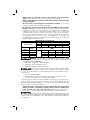
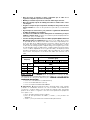
• An extension cord must have adequate wire size (AWG or American Wire
Gauge) for safety. The smaller the gauge number of the wire, the greater the
capacity of the cable, that is 16 gauge has more capacity than 18 gauge. An
undersized cord will cause a drop in line voltage resulting in loss of power and
overheating. When using more than one extension to make up the total length,
be sure each individual extension contains at least the minimum wire size. The
following table shows the correct size to use depending on cord length and
nameplate ampere rating. If in doubt, use the next heavier gauge. The smaller the
gauge number, the heavier the cord.
Minimum Gauge for Cord Sets
Ampere Rating
Volts Total Length of Cord in Feet (meters)
120V 25 (7.6) 50 (15.2) 100 (30.5) 150 (45.7)
240V 50 (15.2) 100 (30.5) 200 (61.0) 300 (91.4)
More
Than
Not More
Than
AWG
0 6 18 16 16 14
610 18161412
10 12 16 16 14 12
12 16 14 12 Not Recommended
ALWAYS use safety glasses. Everyday eyeglasses are NOT safety
glasses. Also use face or dust mask if cutting operation is dusty. ALWAYS WEAR
CERTIFIED SAFETY EQUIPMENT:
• ANSI Z87.1 eye protection (CAN/CSA Z94.3),
• ANSI S12.6 (S3.19) hearing protection,
• NIOSH/OSHA/MSHA respiratory protection.
Some dust created by power sanding, sawing, grinding, drilling,
and other construction activities contains chemicals known to the State of California
to cause cancer, birth defects or other reproductive harm. Some examples of these
chemicals are:
• lead from lead-based paints,
• crystalline silica from bricks and cement and other masonry products, and
• arsenic and chromium from chemically-treated lumber.
Your risk from these exposures varies, depending on how often you do this type of
work. To reduce your exposure to these chemicals: work in a well ventilated area, and
work with approved safety equipment, such as those dust masks that are specially
designed to filter out microscopic particles.
• Avoid prolonged contact with dust from power sanding, sawing, grinding,
drilling, and other construction activities. Wear protective clothing and
wash exposed areas with soap and water. Allowing dust to get into your
mouth, eyes, or lay on the skin may promote absorption of harmful chemicals.
Use of this tool can generate and/or disperse dust, which may cause
serious and permanent respiratory or other injury. Always use NIOSH/OSHA approved
respiratory protection appropriate for the dust exposure. Direct particles away from
face and body.

6
6
Always wear proper personal hearing protection that conforms
to ANSI S12.6 (S3.19) during use. Under some conditions and duration of use, noise
from this product may contribute to hearing loss.
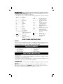
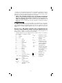
• The label on your tool may include the following symbols. The symbols and their
definitions are as follows:
kW .........................kilowatts
F .............................farads
μF ........................... microfarads
l ..............................litres
g ............................. grams
kg ........................... kilograms
bar .........................bars
Pa ..........................pascals
h .............................hours
min ......................... minutes
s .............................seconds
n
o ..........................no load speed
…/min or min-1 ... Revolutions or
reciprocations per minute
or DC ..... direct current
or AC ...............alternating
2
.................... two-phase alternating
current
2N
.................. two-phase alternating
current with neutral
3
..................... three-phase alternating
current
3N
.................. three-phase alternating
current with neutral
............... rated current of the
appropriate fuse-link in
amperes
................... time-lag miniature fuse-link
where X is the symbol
for the time/current
characteristic, as given in
IEC 60127
.......................... protective earth
.......................... Class II Construction
(double insulated)
IPXX ....................... IP symbol
SAVE THESE INSTRUCTIONS
MOTOR
Be sure your power supply agrees with the nameplate marking. Voltage decrease of
more than 10% will cause loss of power and overheating. PORTER-CABLE tools are
factory tested; if this tool does not operate, check power supply.
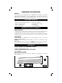
CARTON CONTENTS
• Four height rod sections
• Two cutting bits
• Open end wrench
• Two flat washers
• Two cap screws
• Hex Wrench
• Motor unit
• Mortiser frame
FUNCTIONAL DESCRIPTION
FOREWORD
The Model 513 Lock Mortiser permits builders and contractors to quickly cut true,
accurate mortises for door-box locks.
The Model 517 Lock-Face Template allows quick and economical routing for lock
faces on doors after the mortise has been completed.
INTENDED USE
This heavy-duty door mortisor and face template is designed for professional routing
applications.
DO NOT use under wet conditions or in presence of flammable liquids or gases.
This is a professional power tool. DO NOT let children come into contact with the tool.
Supervision is required when inexperienced operators use this tool.

7
7
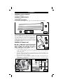
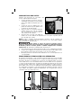
ASSEMBLY
ASSEMBLY TOOLS REQUIRED
Hex wrench (supplied)
ASSEMBLY TIME ESTIMATE
15 to 30 minutes
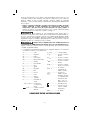
STANDARD EQUIPMENT
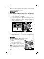
Four sections of the height rod (A), and two mortise bits (B) are furnished (Fig. 1).
A
FIG. 1
B
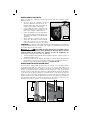
ASSEMBLY OF BASE UNIT
The unit is shipped with the crank handle disassembled.
FIG. 2
A
B
C
D
Remove the bolt and washer (B and C) Fig. 2. Place
the crank handle (D) on the crank shaft (A) with the
crank knob facing out and the “D”-shaped hole in
handle aligned with the flat on the shaft. Place the bolt
(C) through the washer (B) and thread it into the shaft
(A). Tighten securely.
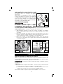
ASSEMBLY OF MOTOR UNIT
To reduce the risk of injury, turn
unit off and disconnect it from power source
before installing and removing accessories,
before adjusting or when making repairs. An
accidental start-up can cause injury.
1. In the hardware package, locate the two cap
screws, two flat washers, and a 5/32" (4.0 mm) hex wrench. Place the washers
on the cap screws.
2. Insert the splined cutter shaft (Fig. 3) through the motor carriage (L) and into the
spiral grooved bushing (M) in the main frame (N). Orient motor as shown in Fig. 8
and seat it into the motor carriage.
3. Insert the two screw and washer assemblies (from Step 1) through the motor
carriage (Fig. 4). Thread them into the holes in the motor housing. Tighten
securely with the hex wrench.
SCREWS & WASHER
FIG. 4
FIG. 3
L
N
M

8
8
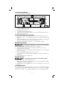
OPERATION
DETERMINE WIDTH OF CUT
Measure the width of the lock box at its widest point, including any protruding parts.
DO NOT INCLUDE THE LOCK FACE. Select a mortise bit equal to, or slightly larger
than this width.
Do not use mortise bits with a diameter in excess of 1-1/4".
EXAMPLE:
1) Overall width of lock box – 31/32" (24.6 mm) Use PORTER-CABLE
#43704PC 1" (25.4 mm) diameter bit.
2) Overall width of lock box – 3/4" (19.1 mm) Use PORTER-CABLE #43703PC
3/4" (19.1 mm) diameter bit.
Various sizes of mortise bits are available as accessories.
Disconnect the tool from the power source and exercise
extreme care when handling the cutter to avoid bodily injury or damage to
the cutting edge.
Thread the selected bit on the end of the splined cutter shaft. Tighten securely.
DETERMINING LENGTH OR HEIGHT OF CUT
Measure the height of the lock box (Fig. 5), including any protruding parts. DO NOT
INCLUDE THE LOCK FACE.
T
U
FIG. 6
FIG. 5
SETTING MORTISER FOR LENGTH OF CUT
To reduce the risk of injury, turn unit off and disconnect it from
power source before installing and removing accessories, before adjusting or
when making repairs. An accidental start-up can cause injury.
Set the mortiser for the length of cut (Fig. 6). Turn the adjusting knob (U) until the
correct graduation mark on the slide aligns with the line on the crank-pin indicating
washer (T). If you find that the adjusting knob (U) is difficult to move, turn the crank (E)
Fig.8 until the tension is relieved.
EXAMPLE: If you want your mortise to be 4" (101.6 mm) long, turn the adjusting
knob (U) Fig. 6 until the graduation mark aligns with the line on the crank-pin indicating
washer.
SETTING MORTISER FOR DEPTH OF CUT
To reduce the risk of injury, turn unit off and disconnect it from
power source before installing and removing accessories, before adjusting or
when making repairs. An accidental start-up can cause injury.

9
9
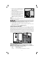
Measure the lock box at its deepest part, including the thickness of the lock face. Add
1/4" (6.4 mm) for clearance. The depth of cut is controlled by the feed rod (W) Fig. 7
which is marked in 1/4" (6.4 mm) increments. Loosen the collar (F) and move it to the
determined depth requirement. Lock it in place.
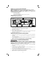
MAKING A TRIAL CUT
To reduce the risk of injury, turn unit off and disconnect it from
power source before installing and removing accessories, before adjusting or
when making repairs. An accidental start-up can cause injury.
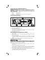
After set-up, make a trial cut to ensure the fit of the lock box.
1. Clamp a length of 2" x 6" (50.8 x 152.4 mm), or larger lumber in vise, or fasten it
securely to a work bench, in an upright position.
2. Move the feed lever (A) to the horizontal position (Fig. 8). Pull the motor carriage
(B) to the end of the guide rod (C).
3. Place the mortiser against the edge of the 2" x 6" so that the clamps are firmly
seated. The crank (E) will be free to revolve. Tighten the clamp handles (D)
securely to hold the mortiser in position.
4. Move the feed lever (A) to the vertical position to engage the feed mechanism.
W
F
FIG. 7
FIG. 8
B
F
D
A
E
C
Make sure that the motor switch is in the "OFF" position.
5. Connect the mortiser to the power source.
6. Turn motor switch "ON" and rotate the crank (E) until the collar (F) hits the feed
housing, stopping the depth of cut and completing the mortise. Be careful not to
overload the motor by rotating the crank too fast.
7. Turn the motor "OFF".
To reduce the risk of injury, turn unit off and disconnect it from
power source before installing and removing accessories, before adjusting or
when making repairs. An accidental start-up can cause injury.
8. Move the feed lever (A) to the horizontal
B
FIG. 9
position.
9. Grasp the motor carriage (B) Fig. 9 with both
hands and pull toward you until the bit is clear.
Remove the mortiser from 2" X 6".
10. Remove all chips from the cut and test the
lock box for fit. If necessary, readjust the
mortiser and make another trial cut.
NOTE: Be sure the length of the mortise cut has
not removed the stock required for the two screws
that retain the lock box to the door.
MORTISING A DOOR
After you make a successful trial cut, mortise the
door.

10
10
1. Place the door in an upright position and
FIG. 10
anchor it securely. If the door is hung, use
wedges under the bottom of the door to
keep it from moving.
2. Place the lock box against the side of the
door at the desired distance from the floor.
3. Make a mark on the side of the door at the
top of the lock box (Fig. 10). Transfer this
mark to the front edge of the door.
4. Draw a line 3/8" (9.5 mm) above this mark
across the front edge of the door. This is
required for clearance for the radius of the
cutter.
NOTE: The actual clearance may be
determined from the lock box and the trial cut in the 2" X 6". This clearance may be
used in place of 3/8" (9.5 mm).
To reduce the risk of injury, turn unit off and disconnect it from
power source before installing and removing accessories, before adjusting or
when making repairs. An accidental start-up can cause injury.
5. Turn the mortiser crank handle until the bit is in the top-most position.
6. Place the mortiser on the door so that the top edge of the bit touches the line
drawn on edge of the door.
7. Mortise the door as instructed in Making A Trial Cut.
PRODUCTION LOCK MORTISING
If you have a number of doors with the locks at the same height, the height-rod
attachment (Fig. 11) can be of great value. After you have determined the correct
height, and have the lock mortiser in position on the first door, attach the four rods
that compose the height-rod attachment. Insert the rods in the mortiser and place the
height rod stop (G) on the top of the rod so that it rests on the top of the door. Lock
the height-rod screws (H) Fig. 12. To locate the mortiser on the next door, place the
mortiser on the door with the height-rod stop resting on the top of the door and tighten
the clamps. This will assure having all locks located in the same position.
G
FIG. 11
H
FIG. 12
MODEL 517 LOCK FACE TEMPLATE
REQUIRED EQUIPMENT: Router (not included) and Lock Face Template
NOTE: The lock face template is to be used with a router only. DO NOT use
the lock face template with the lock mortiser motor.
42024 Template Guide (included)
42237 Locknut (Included)
43440PC 5/8" (15.9 mm) Diameter Straight Bit (not included)

11
11
SETTING UP THE TEMPLATE
1. Loosen the locking screw (A) Fig. 13.
A
C
C
D
B
E
F
G
FIG. 13
2. Adjust the side guides (C) Fig. 13, so that the space between them is 1/8"
(3.2mm) wider than the lock face.
3. Firmly tighten the screw (A).
4. Loosen the locking screw (D) Fig. 13.
5. Adjust the distance between (E) and (B) to 1/8" (3.2 mm) longer than the lock face.
6. Firmly tighten the screw (D).
LOCATING THE TEMPLATE ON THE DOOR
1. Draw a line across the door edge at the center of the mortise cut for the lock.
2. Draw a line (F) Fig. 13 on the template side guides (C), midway between bars (B)
and (E).
3. Position the template on door so that the line (F) on the template matches the line
drawn on the door edge at the center of the mortise cut.
4. Tighten the two wing screws (G) Fig. 13 to lock the template in place.
PREPARING THE ROUTER
To reduce the risk of injury, turn unit off and disconnect it from
power source before installing and removing accessories, before adjusting or
when making repairs. An accidental start-up can cause injury.
1. Attach the 42024 template guide to the router base with 42237 lock nut.
2. Install the bit in the router collet.
3. Set the router on the lock face template. Adjust the depth of cut so that the bit
just touches the door.
4. Set the router-depth adjusting ring to the zero position.
5. Lift the router from the template. Adjust the depth-of-cut equal to the thickness of
the lock face.
6. Firmly tighten the motor-locking device.
MAKING THE CUT
Make sure that the motor switch is in the "OFF" position.
1. Connect the router cord to the power source.
2. Mortise the door for the lock face, guiding the router by keeping the template
guide against the template guide bars.
3. A corner chisel 42234 is available as an accessory for squaring the corners for the
lock face.
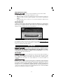
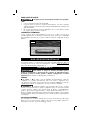
FINISHED MORTISE
The completed mortise is illustrated in Fig. 14. The cut is smooth and even and you
can insert the lock box with no further hand work. In Fig. 14, the lock face template
has been used and the corner chisel has squared the corners, assuring a perfect fit.

12
12
FIG. 14
.
TROUBLESHOOTING
For assistance with your tool, visit our website at www.portercable.com for a list of service
centers, or call the PORTER-CABLE Customer Care Center at (888) 848-5175.
MAINTENANCE
To reduce the risk of injury, turn unit off and disconnect it from
power source before installing and removing accessories, before adjusting or
when making repairs. An accidental start-up can cause injury.
CLEANING
Periodically blowing dust and chips out of the motor housing using clean,
dry compressed air is a suggested maintenance procedure. To reduce the risk of serious
personal injury, ALWAYS wear ANSI Z87.1 safety glasses while using compressed air.
When cleaning, use only mild soap and a damp cloth on plastic parts.
Many household cleaners contain chemicals which could seriously damage plastic. Also,
do not use gasoline, turpentine, lacquer, paint thinner, dry cleaning fluids or similar products
which may seriously damage plastic parts. NEVER let any liquid get inside the tool; NEVER
immerse any part of the tool into a liquid.
FAILURE TO START
Should your tool fail to start, check to make sure the prongs on the cord plug are making
good contact in the outlet. Also, check for blown fuses or open circuit breakers in the line.
LUBRICATION
This tool has been lubricated with a sufficient amount of high grade lubricant for the life of
the unit under normal operating conditions. No further lubrication is necessary.
BRUSH INSPECTION
For your continued safety and electrical protection, brush inspection and replacement
on this tool should ONLY be performed by a PORTER-CABLE FACTORY SERVICE
CENTER OR PORTER-CABLE AUTHORIZED WARRANTY SERVICE CENTER.
At approximately 100 hours of use, take or send your tool to your nearest PORTER-CABLE
Factory Service center or PORTER-CABLE Authorized Warranty Service Center to be
thoroughly cleaned and inspected. Have worn parts replaced and lubricated with fresh
lubricant. Have new brushes installed, and test the tool for performance.
Any loss of power before the above maintenance check may indicate the need for
immediate servicing of your tool. DO NOT CONTINUE TO OPERATE TOOL UNDER THIS
CONDITION. If proper operating voltage is present, return your tool to the service station
for immediate service.
SERVICE
REPLACEMENT PARTS
Use only identical replacement parts. For a parts list or to order parts, visit our
service website at www.portercable.com. You can also order parts from your nearest
PORTER-CABLE Factory Service Center or PORTER-CABLE Authorized Warranty
Service Center. Or, you can call our Customer Care Center at (888) 848-5175.

13
13
SERVICE AND REPAIRS
All quality tools will eventually require servicing and/or replacement of parts. For information
about PORTER-CABLE, its factory service centers or authorized warranty service centers,
visit our website at www.portercable.com or call our Customer Care Center at (888) 848-
5175. All repairs made by our service centers are fully guaranteed against defective material
and workmanship. We cannot guarantee repairs made or attempted by others.
You can also write to us for information at PORTER-CABLE, 4825 Highway 45 North,
Jackson, Tennessee 38305 - Attention: Product Service. Be sure to include all of the
information shown on the nameplate of your tool (model number, type, serial number, etc.).
ACCESSORIES
Since accessories, other than those offered by PORTER-CABLE,
have not been tested with this product, use of such accessories with this tool could be
hazardous. To reduce the risk of injury, only PORTER-CABLE recommended accessories
should be used with this product.
A complete line of accessories is available from your PORTER-CABLE Factory Service
Center or a PORTER-CABLE Authorized Warranty Service Center. Please visit our Web Site
www.portercable.com for a catalog or for the name of your nearest supplier.
THREE YEAR LIMITED WARRANTY
PORTER-CABLE will repair, without charge, any defects due to faulty materials or
workmanship for three years from the date of purchase. This warranty does not cover
part failure due to normal wear or tool abuse. For further detail of warranty coverage
and warranty repair information, visit www.portercable.com or call (888) 848-5175. This
warranty does not apply to accessories or damage caused where repairs have been made
or attempted by others. This warranty gives you specific legal rights and you may have other
rights which vary in certain states or provinces.
In addition to the warranty, PORTER-CABLE tools are covered by our:
1 YEAR FREE SERVICE: PORTER-CABLE will maintain the tool and replace worn parts
caused by normal use, for free, any time during the first year after purchase.
90 DAY MONEY BACK GUARANTEE: If you are not completely satisfied with the
performance of your PORTER-CABLE Power Tool, Laser, or Nailer for any reason, you
can return it within 90 days from the date of purchase with a receipt for a full refund – no
questions asked.
To register your tool for warranty service visit our website at www.portercable.com.
LATIN AMERICA: This warranty does not apply to products sold in Latin America. For
products sold in Latin America, see country specific warranty information contained in the
packaging, call the local company or see website for warranty information.
WARNING LABEL REPLACEMENT
If your warning labels become illegible or are missing, call (888) 848-5175 for a free
replacement.
Page is loading ...
Page is loading ...
Page is loading ...
Page is loading ...
Page is loading ...
Page is loading ...
Page is loading ...
Page is loading ...
Page is loading ...
Page is loading ...
Page is loading ...
Page is loading ...
Page is loading ...
Page is loading ...
Page is loading ...
Page is loading ...
Page is loading ...
Page is loading ...
Page is loading ...
Page is loading ...
Page is loading ...
Page is loading ...
Page is loading ...
Page is loading ...
Page is loading ...
Page is loading ...
Page is loading ...
Page is loading ...
Page is loading ...
Page is loading ...
Page is loading ...
-
 1
1
-
 2
2
-
 3
3
-
 4
4
-
 5
5
-
 6
6
-
 7
7
-
 8
8
-
 9
9
-
 10
10
-
 11
11
-
 12
12
-
 13
13
-
 14
14
-
 15
15
-
 16
16
-
 17
17
-
 18
18
-
 19
19
-
 20
20
-
 21
21
-
 22
22
-
 23
23
-
 24
24
-
 25
25
-
 26
26
-
 27
27
-
 28
28
-
 29
29
-
 30
30
-
 31
31
-
 32
32
-
 33
33
-
 34
34
-
 35
35
-
 36
36
-
 37
37
-
 38
38
-
 39
39
-
 40
40
-
 41
41
-
 42
42
-
 43
43
-
 44
44


Ask a question and I''ll find the answer in the document
Finding information in a document is now easier with AI
in other languages
- français: Porter Cable 513 Manuel utilisateur
- español: Porter Cable 513 Manual de usuario
Related papers
Other documents
-
 Steel City 25200 User manual
-
 Steel City 25200 User manual
-
Powermatic 719T Mortiser, 1HP 1PH 115/230V User manual
-
Powermatic 1791264K User manual
-
Wen 43012 User manual
-
-
Rikon Power Tools 34-255 User manual
-
-
King Canada MA-1050ST User manual
-

